This article gives information about the support power management in OpenSTlinux for STM32MP2 series.
1. Framework purpose[edit | edit source]
The purpose of this article is to explain how OpenSTlinux components handle the STM32MP2 series power management:
- Software overview
- Peripheral power support
- Low-power modes available on the device
See also the page How to define your low-power strategy.
2. Software overview[edit | edit source]
In OpenSTLinux,the device power requests associated to each system resources (clock, regulator, operation point) are provided by the secure world of the trusted domain through SCMI requests.
For Cortex-A35 non-secure world, the device request are consolidated by the Linux frameworks before to use SCMI framework.
The Linux system power request is handled with the PSCI support and TF-A BL31 and treated by trusted domain.
2.1. A35-TD flavor  [edit | edit source]
The SCMI server is provided by OP-TEE for all users and the PSCI power request is treated by Cortex-A35 in TF-A BL31:

In details, the PSCI power request is treated by TF-A BL31 running in SYSRAM with support of OP-TEE running in DDR for system resources (STPMIC for example) or secure devices:
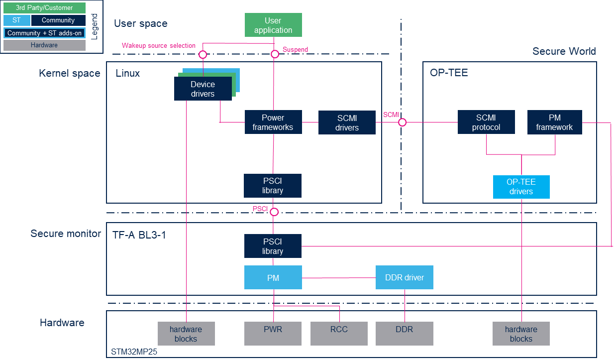
2.2. M33-TD flavor [edit | edit source]
The SCMI server is provided by TF-M for all users and the PSCI requests is forwarded to Cortex-M33 firmware with SCMI message:

In details the power requests from Cortex-A35 is received by TF-M SCMI server and transmit with SCMI notification to Cortex-M33 non-secure firmware.
When the STM32Cube firmware allows the low power mode (the idle task and the power manager application need to check inactivity, activated wake-up and latency constraint for allow and select the correct low power mode), it suspend the applications (suspend the Cortex-A35 with rproc services and stop the the Cortex-M33 non-secure scheduling) and requets the selected low power mode to TF-M with PM service.
The low power mode requests is treated by TF-M running in DDR (including suspend of driver of secure device, as STPMIC to prepare low power mode) with help of STM32MP2 low power firmware running in RETRAM for management of DDR self refresh mode and for standby wake-up:

2.3. Component description[edit | edit source]
The OpenSTLinux components for low-power mode are:
Nonsecure world (Linux):
- Power management frameworks: see Power overview for details
- PSCI library: this is a set of standardized functions to request a low-power service to the secure monitor.
- SCMI drivers: driver for system resources (clock, regulators, power domain,...), exposed by OP-TEE with SCMI protocol.
- Device driver: any peripheral driver which needs to control power.
- RCC driver for clock and reset managed by nonsecure world
Secure world components (OP-TEE):
- SCMI protocol: see SCMI overview for details.
- PM framework: call the low-power callback of each device on the call of TF-A BL31 PM hooks.
- OP-TEE drivers: driver of device for system resources (only for A35-TD flavor ).
- RCC driver for clock and reset managed by secure world.
- PWR driver for SoC regulators managed by secure world.
- PMIC driver for external regulators
Secure monitor components (TF-A BL31):
- PSCI library: generic PSCI stack.
- PM: manage PSCI topology and modes with RCC and PWR registers
- DDR driver: DDR driver (manage DDR self refresh only for A35-TD flavor ).
TF-M secure OS on Cortex-M33 (only for M33-TD flavor ):
- SCMI protocol: based in SCP library, see SCMI overview for details.
- PM service: STM32MP2 service used to handle low power request by Cortex-M33 non-secure firmware
- TF-M drivers: driver of device for system resources managed by SCMI
- RCC driver for clock and reset managed by secure world.
- PWR driver for SoC regulators managed by secure world.
- PMIC driver for external regulators
STM32MP2 low power firmware (only for M33-TD flavor ): RETRAM firmware installed and used by TF-M STM32MP2 PM service
- DDR driver: DDR driver (manage DDR self refresh only for M33-TD flavor ).
- SCMI agent
- Low power manager:
- consolidate requests for Cortex-A firmwares (SCMI notificaiton) and Cortex-M non-secure application
- request system low power (with DDR self-refresh) to TF-M with pm service API
STM32 peripherals (Hardware):
2.4. API description[edit | edit source]
The OpenSTLinux power management support is based on Arm® interface specifications:
- Power state coordination interface (PSCI) [1] defines many messages (see identifiers in TF-A include/lib/psci/psci.h or in Linux include/kvm/arm_psci.h ), for examples:
- CPU_SUSPEND : used to CPU suspend (freeze/s2idle), including OS initiated state support for CpuIdle.
- CPU_ON/CPU_OFF : used for hotplug feature.
- SYSTEM_OFF : used for power off.
- SYSTEM_RESET : used for system reset.
- SYSTEM_SUSPEND : used to system suspend (deep).
- PSCI_VERSION : return the supported version of the PSCI specication, v1.1 is supported by TF-A.
- System Control and Management Interface (SCMI)[2], see SCMI overview for details.
And for M33-TD flavor on:
- TF-M services
- PSA Certified APIs[3]
- STMP32MP2 low power firmware API
3. Configuration[edit | edit source]
The objective of this chapter is to explain how to configure OpenSTLinux for #Low-power modes based on:
- OP-TEE and TF-A device tree
- TF-M device tree for M33-TD flavor
See the page power overview for kernel configuration details.
3.1. Supported power modes[edit | edit source]
The SoC device tree describes the PSCI topology in sub-nodes of cpus/domain-idle-states:
- for Linux in SoC device tree (arch/arm64/boot/dts/st/stm32mp211.dtsi , arch/arm64/boot/dts/st/stm32mp231.dtsi , arch/arm64/boot/dts/st/stm32mp251.dtsi ), one node for each PSCI_CPU_SUSPEND supported parameter (only the Stop1 modes for OSI and S2Idle support):
domain-idle-states {
	STOP1: domain-stop1 {
		compatible = "domain-idle-state";
		arm,psci-suspend-param = <0x00000011>;
	};
	LP_STOP1: domain-lp-stop1 {
		compatible = "domain-idle-state";
		arm,psci-suspend-param = <0x0000021>;
	};
	LPLV_STOP1: domain-lplv-stop1 {
		compatible = "domain-idle-state";
		arm,psci-suspend-param = <0x00000211>;
	};
};
- For TF-A BL31 secure monitor, in SoC device tree (fdts/stm32mp211.dtsi , fdts/stm32mp231.dtsi , fdts/stm32mp251.dtsi ), one node by state supported in PSCI topology:
domain-idle-states {
	domain-stop1 {
		compatible = "domain-idle-state";
		arm,psci-suspend-param = <0x00000011>;
	};
	domain-lp-stop1 {
		compatible = "domain-idle-state";
		arm,psci-suspend-param = <0x00000021>;
	};
	domain-lplv-stop1 {
		compatible = "domain-idle-state";
		arm,psci-suspend-param = <0x00000211>;
	};
	domain-stop2 {
		compatible = "domain-idle-state";
		arm,psci-suspend-param = <0x40001333>;
	};
	domain-lp-stop2 {
		compatible = "domain-idle-state";
		arm,psci-suspend-param = <0x40002333>;
	};
	domain-lplv-stop2 {
		compatible = "domain-idle-state";
		arm,psci-suspend-param = <0x40023333>;
	};
	domain-standby {
		compatible = "domain-idle-state";
		arm,psci-suspend-param = <0x40033333>;
	};
};
The unsupported low-power modes and associated references in domain-idle-states power domain nodes must be deleted from TF-A BL31 and Linux board device-tree files.
For example on board without STPMIC25, if the PWR_LP pins control the reduced voltage mode of the VDDCORE and VDDCPU regulators, then only LPLV-StopX modes can be reached. LP-StopX modes must be deleted.
- In TF-A BL31 device tree:
/ {
	cpus {
		domain-idle-states {
			/delete-node/ domain-lp-stop1;
			/delete-node/ domain-lp-stop2;
		};
	};
};
- In Linux device tree (CLUSTER_PD
domain-idle-states = <&STOP1>, <&LP_STOP1>;for CLUSTER_PD in arch/arm64/boot/dts/st/stm32mp251.dts ):
/ {
	cpus {
		domain-idle-states {
			/delete-node/ domain-lp-stop1;
		};
	};
};

&CLUSTER_PD {
	domain-idle-states = <&STOP1>;
};
For M33-TD flavor , only the supported mode must be managed in low power manager of Cortex-M33 non secure firmware.
3.2. STPMIC configuration for low-power mode[edit | edit source]
3.2.1. Bindings[edit | edit source]
This PMIC configuration for low power mode is done in OpenSTLinux by the trusted domain firmware, based on associated device tree:
- OP-TEE for A35-TD flavor
- TF-M for M33-TD flavor
Refer to PMIC page for details of PMIC configuration in OpenSTLinux for each power mode and to application note AN5727 for configurations.
Each regulator of STPMIC can automatically change its configuration with the associated STPMIC power control pins (use the xxx_ALT_CR registers ) and the STPMIC binding defines properties to manage this alternate configuration for each regulator node:
- st,pwrctrl-enable is not set: NO control pin, the regulator never switch to alternate configuration
- st,pwrctrl-enable and st,pwrctrl-sel = <X>:
the regulator switches to alternate when selected power control X is low
The alternate configuration is defined in device tree subnodes associated to each system power level:
- default for Stop1, LP-Stop1, Stop2, LP-Stop2
- lplv for LPLV-Stop1, LPLV-Stop2
- standby for Standby/Standy1
- off for Power-off=Standby2/Standby2 with DDR off
- st,pwrctrl-reset and st,pwrctrl-sel = <X>:
the regulator is disabled when when the selected power control X is low and the regulator switches to to it's NVMEM default value when exit from low power
The STM32 MPU reference manual describes the STM32 MPU pins behaviors for low power modes:
- chapter"Reset and clock control (RCC)" for NRSTC1MS
- chapter "PWR power modes" for PWR_ON and PWR_CPU_ON in the table "External regulators control".
The STMicroelectronics boards use the AN5727 configuration with
- the STM32MPU power control pin configuration:
- PWR_D2CR[LPCFG_D2]=1, PWR_ON pin is low in Standby, LP-Stop1, LP-Stop2, LPLV-Stop1 and LPLV-Stop2 modes
- PWR_D1CR[LPCFG_D1]=0, PWR_CPU_ON pin is low when CA355 is in DStandby mode, so for D2 system modes Run2, Stop2, LP-Stop2, LPLV-Stop2 and Standby
- the STPMIC power control pins are connected to STM32 MPU pins:
- PWRCTRL1=PWR_ON
- PWRCTRL2=PWR_CPU_ON
- PWRCTRL3=NRSTC1MS + PWR_CPU_ON
this powerctrl produces a pulse during exit of Stop2, Standby or Run2/D1 DStandby
it is used for power cycle on regulator used for external mass-storage devices, boot devices, with st,pwrctrl-reset.
This default PWR configuration is done in the trusted domain firmware but it can be changed in device tree as described in pwr binding files:
- TF-A BL31 for A35-TD flavor
- TF-M for M33-TD flavor
with pwr node properties:
- st,popl-d1-ms
- st,podh-d2-ms
- st,popl-d2-ms
- st,lpcfg-d2
- st,lplvdly-d2
- st,lpstop1dly-us (only for TF-A)
3.2.2. STPMIC with A35-TD flavor [edit | edit source]
In OpenSTLinux, the selected PSCI power level is indicated to OP-TEE with Secure-EL1 Payload Dispatcher (SPD) PSCI hooks. And this power level is indicated with pm_hint to each OP-TEE drivers to save/restore the device configuration (see core/include/kernel/pm.h and core/arch/arm/plat-stm32mp2/stm32mp_pm.h for details).
This hook is used by the STPMIC25 driver in OP-TEE to configure each regulators for low power modes.
See OP-TEE device tree in core/arch/arm/dts/stm32mp257f-ev1.dts for VDDCORE configuration example:
	vddcore: buck2 {
		regulator-name = "vddcore";
		regulator-min-microvolt = <820000>;
		regulator-max-microvolt = <820000>;
		regulator-always-on;
		st,pwrctrl-sel = <1>;
		st,pwrctrl-enable;

		default {
			regulator-on-in-suspend;
			regulator-suspend-microvolt = <820000>;
		};
		lplv {
			regulator-on-in-suspend;
			regulator-suspend-microvolt = <670000>;
		};
		standby {
			regulator-off-in-suspend;
		};
		off {
			regulator-off-in-suspend;
		};
	};
In this example VDDCORE uses the STPMIC configuration
- normal when PWR_ON=1
0.82V for Run1, Run2, Stop1, Stop2 - alternate when PWR_ON=0, define with nodes
- default with 0.82V for LP-Stop1, LP-Stop2
- lplv with 0.67V for LPLV-Stop1, LPLV-Stop2
- standby off for Standby1
- off off for power off request (Standby2 / Vbat)
On the STMicroelectronics boards, VDDCPU is provided by a STPMIC buck and is defined in device tree:
- st,pwrctrl-sel = <2>: selects control by STPMIC pin PWRCTRL2 connected to STM32 MPU pin CPU_ON:
- its voltage doesn't change for Run1, Stop1, LP-Stop1 and LPLV-Stop1, because we can't differentiate the Stop1 modes with PWR_CPU_ON = 1
- the supply is OFF for all the other modes, Stop2 or Standby, when PWR_CPU_ON = 0 with the STPMIC xxx_ALT_CR registers.
See OP-TEE device tree in core/arch/arm/dts/stm32mp257f-ev1.dts for VDDCPU configuration example:
	vddcpu: buck1 {
		regulator-name = "vddcpu";
		regulator-min-microvolt = <800000>;
		regulator-max-microvolt = <910000>;
		regulator-always-on;
		st,pwrctrl-sel = <2>;
		st,pwrctrl-enable;

		default {
			regulator-off-in-suspend;
		};
		lplv {
			regulator-off-in-suspend;
		};
		standby {
			regulator-off-in-suspend;
		};
		off {
			regulator-off-in-suspend;
		};
	};
This STPMIC hardware reference design used by STMicroelectronics boards have one restriction:
VDDCPU is not reduced in LPLV-Stop1 low power and stay at nominal voltage 0.8V.
See OP-TEE device tree in core/arch/arm/dts/stm32mp257f-ev1.dts for boot devices, e•MMC and SD card, configuration example:
	vdd_emmc: ldo2 {
		regulator-name = "vdd_emmc";
		regulator-min-microvolt = <3300000>;
		regulator-max-microvolt = <3300000>;
		regulator-over-current-protection;
		st,pwrctrl-sel = <3>;
		st,pwrctrl-reset;
	};
...
	vdd_sdcard: ldo7 {
		regulator-name = "vdd_sdcard";
		regulator-min-microvolt = <3300000>;
		regulator-max-microvolt = <3300000>;
		regulator-over-current-protection;
		st,regulator-bypass-microvolt = <3300000>;
		st,pwrctrl-sel = <3>;
		st,pwrctrl-reset;
	};
	vddio_sdcard: ldo8 {
		regulator-name = "vddio_sdcard";
		regulator-min-microvolt = <1800000>;
		regulator-max-microvolt = <3300000>;
		regulator-over-current-protection;
		st,regulator-bypass-microvolt = <3300000>;
		st,pwrctrl-sel = <3>;
		st,pwrctrl-reset;
	};
One full example of this configuration is given chapter 5.3.2 LP-Stop1/LPLV-Stop1 mode of AN5727 with Table 10. and Table 11..
Anyway OpenSTLinux respects the next constraints on STMicroelectropnics board with STPMIC:
- All the low power mode are supported
- the STPMIC configuration is not changed dynamically for Run1/Stop1/LP-Stop1 modes to avoid latency issue with PSCI OSI support (no pwrctrl reconfiguration for entry Stop1 or LP-Stop1, the default configuration is restore after other modes).
- the VDDCPU Cortex-A35 supply voltage follows the Datasheets recommendation for LPLV-Stop1:
- Min : 0.64 V
- Typical: 0.67 V
- Max 0.842 V
If this restriction on VDDCPU for LPLV-Stop1 mode is not acceptable, an other hardware design (by example with an other power control mapping) or an other STPMIC configuration (with a reduced number of supported modes) must be used by customer.
3.2.3. STPMIC with M33-TD flavor [edit | edit source]
In TF-M, the selected power level is indicated by PM service to each driver by PM function pm_suspend_devices() and the power level is indicated with parameter pm_hint to each OP-TEE drivers to save/restore the device configuration (see platform/ext/target/stm/common/stm32mp2xx/native_driver/include/pm/pm.h for details).
This parameter is used by the STPMIC driver in TF-M to configure each regulators for low power modes as described in device tree with properties.
The T-M device tree example, based on of AN5727 is available in stm32mp2/m33-td/tfm/stm32mp257f-dk-cm33tdcid-ostl-sdcard-s.dts :
	stpmic25: pmic@33 {
		compatible = "st,stpmic2";
		reg = <0x33>;
		status = "okay";

		regulators {
			compatible = "st,stpmic2-regulators";

			vddcpu: buck1 {
				regulator-name = "vddcpu";
				regulator-min-microvolt = <800000>;
				regulator-max-microvolt = <910000>;
				regulator-always-on;
				st,pwrctrl-sel = <2>;
				st,pwrctrl-enable;

				default {
					regulator-off-in-suspend;
				};
				lplv {
					regulator-off-in-suspend;
				};
				standby {
					regulator-off-in-suspend;
				};
				off {
					regulator-off-in-suspend;
				};
			};
			vddcore: buck2 {
				regulator-name = "vddcore";
				regulator-min-microvolt = <820000>;
				regulator-max-microvolt = <820000>;
				regulator-always-on;
				st,pwrctrl-sel = <1>;
				st,pwrctrl-enable;

				default {
					regulator-on-in-suspend;
					regulator-suspend-microvolt = <820000>;
				};
				lplv {
					regulator-on-in-suspend;
					regulator-suspend-microvolt = <670000>;
				};
				standby {
					regulator-off-in-suspend;
				};
				off {
					regulator-off-in-suspend;
				};
			};
			vddgpu_pmic: buck3 {
				regulator-name = "vddgpu_pmic";
				regulator-min-microvolt = <800000>;
				regulator-max-microvolt = <900000>;
				regulator-over-current-protection;

				standby {
					regulator-off-in-suspend;
				};
				off {
					regulator-off-in-suspend;
				};
			};
			vddio_pmic: buck4 {
				regulator-name = "vddio_pmic";
				regulator-min-microvolt = <3300000>;
				regulator-max-microvolt = <3300000>;
				regulator-always-on;
				st,mask-reset;
				st,pwrctrl-sel = <1>;
				st,pwrctrl-enable;

				default {
					regulator-on-in-suspend;
					regulator-suspend-microvolt = <3300000>;
				};
				lplv {
					regulator-on-in-suspend;
					regulator-suspend-microvolt = <3300000>;
				};
				standby {
					regulator-on-in-suspend;
					regulator-suspend-microvolt = <3300000>;
				};
				off {
					regulator-on-in-suspend;
					regulator-suspend-microvolt = <3300000>;
				};
			};
			v1v8: buck5 {
				regulator-name = "v1v8";
				regulator-min-microvolt = <1800000>;
				regulator-max-microvolt = <1800000>;
				regulator-always-on;
				st,pwrctrl-sel = <1>;
				st,pwrctrl-enable;

				default {
					regulator-on-in-suspend;
					regulator-suspend-microvolt = <1800000>;
				};
				lplv {
					regulator-on-in-suspend;
					regulator-suspend-microvolt = <1800000>;
				};
				standby {
					regulator-off-in-suspend;
				};
				off {
					regulator-off-in-suspend;
				};
			};
			vdd2_ddr: buck6 {
				regulator-name = "vdd2_ddr";
				regulator-min-microvolt = <1100000>;
				regulator-max-microvolt = <1100000>;
				regulator-always-on;
				st,pwrctrl-sel = <1>;
				st,pwrctrl-enable;

				default {
					regulator-on-in-suspend;
					regulator-suspend-microvolt = <1100000>;
				};
				lplv {
					regulator-on-in-suspend;
					regulator-suspend-microvolt = <1100000>;
				};
				standby {
					regulator-on-in-suspend;
					regulator-suspend-microvolt = <1100000>;
				};
				off {
					regulator-off-in-suspend;
				};
			};
			v3v3: buck7 {
				regulator-name = "v3v3";
				regulator-min-microvolt = <3300000>;
				regulator-max-microvolt = <3300000>;
				regulator-always-on;
				regulator-over-current-protection;
				st,pwrctrl-sel = <1>;
				st,pwrctrl-enable;

				default {
					regulator-on-in-suspend;
					regulator-suspend-microvolt = <3300000>;
				};
				lplv {
					regulator-on-in-suspend;
					regulator-suspend-microvolt = <3300000>;
				};
				standby {
					regulator-off-in-suspend;
				};
				off {
					regulator-off-in-suspend;
				};
			};
			vdda1v8_aon: ldo1 {
				regulator-name = "vdda1v8_aon";
				regulator-min-microvolt = <1800000>;
				regulator-max-microvolt = <1800000>;
				regulator-always-on;
				st,alternate-input-source;
				st,mask-reset;
			};
			vdd_emmc: ldo2 {
				regulator-name = "vdd_emmc";
				regulator-min-microvolt = <3300000>;
				regulator-max-microvolt = <3300000>;
				regulator-over-current-protection;
				st,pwrctrl-sel = <3>;
				st,pwrctrl-reset;
			};
			vdd1_ddr: ldo3 {
				regulator-name = "vdd1_ddr";
				regulator-min-microvolt = <1800000>;
				regulator-max-microvolt = <1800000>;
				regulator-always-on;
				st,pwrctrl-sel = <1>;
				st,pwrctrl-enable;

				default {
					regulator-on-in-suspend;
					regulator-suspend-microvolt = <1800000>;
				};
				lplv {
					regulator-on-in-suspend;
					regulator-suspend-microvolt = <1800000>;
				};
				standby {
					regulator-on-in-suspend;
					regulator-suspend-microvolt = <1800000>;
				};
				off {
					regulator-off-in-suspend;
				};
			};
			vdd3v3_usb: ldo4 {
				regulator-name = "vdd3v3_usb";
				regulator-min-microvolt = <3300000>;
				regulator-max-microvolt = <3300000>;
				regulator-over-current-protection;

				standby {
					regulator-off-in-suspend;
				};
				off {
					regulator-off-in-suspend;
				};
			};
			v5v_hdmi: ldo5 {
				regulator-name = "v5v_hdmi";
				regulator-min-microvolt = <5000000>;
				regulator-max-microvolt = <5000000>;
				st,regulator-bypass-microvolt = <5000000>;
				st,pwrctrl-sel = <0>;
				st,pwrctrl-enable;
			};
			v5v_vconn: ldo6 {
				regulator-name = "v5v_vconn";
				regulator-min-microvolt = <4000000>;
				regulator-max-microvolt = <4000000>;
				regulator-always-on;
				st,regulator-bypass-microvolt = <4000000>;
				st,pwrctrl-sel = <0>;
				st,pwrctrl-reset;
			};
			vdd_sdcard: ldo7 {
				regulator-name = "vdd_sdcard";
				regulator-min-microvolt = <3300000>;
				regulator-max-microvolt = <3300000>;
				regulator-over-current-protection;
				st,regulator-bypass-microvolt = <3300000>;
				st,pwrctrl-sel; = <3>;
				st,pwrctrl-reset;
			};
			vddio_sdcard: ldo8 {
				regulator-name = "vddio_sdcard";
				regulator-min-microvolt = <1800000>;
				regulator-max-microvolt = <3300000>;
				regulator-over-current-protection;
				st,regulator-bypass-microvolt = <3300000>;
				st,pwrctrl-sel = <3>;
				st,pwrctrl-reset;
			};
		};
4. How to use the framework[edit | edit source]
4.1. Low-power modes[edit | edit source]
Refer to STM32 MPU reference manuals for the full description of low-power modes.
The AN5726 Guidelines for using low-power modes on STM32MP2 MPU also gives much more information on these modes and on associated the wake-up sources.
| System mode | Linux Command | PSCI request | Power consumption | Wake-up time | VDDCPU | VDDCORE | DDR state |
|---|---|---|---|---|---|---|---|
| Stop1 | freeze (s2idle) |
PSCI_CPU_SUSPEND | Medium | Low | ON | ON | SR, VTT on |
| LP-Stop1 | Medium | Low | SR, VTT off | ||||
| LPLV-Stop1STM32MP23 STM32MP25[OSTL 1] | Medium | Medium | ON |
ON (reduced) | |||
| Run2[OSTL 3] | mem (deep) |
PSCI_SYSTEM_SUSPEND | Low | Low | OFF | ON | ON for M33-TD flavor SR, VTT off for A35-TD flavor
|
| Stop2 | Low | Low | ON | SR, VTT off | |||
| LP-Stop2 | Low | Medium | |||||
| LPLV-Stop2 | Low | Medium | ON (reduced) | ||||
| StandbySTM32MP21 Standby1STM32MP23 STM32MP25 |
Low | High | OFF | ||||
| StandbySTM32MP21 Standby2STM32MP23 STM32MP25 |
shutdown | PSCI_SYSTEM_OFF | Very-Low | High | Off | ||
| VBAT | Very-Low | Very-High | |||||
| switch OFF[OSTL 4] | Very-Low | Cold Boot |
- ↑ LPLV-Stop1 is not supported in OpenSTLinux for STM32MP21x lines
 as Linux have no HR timer available in this mode (no LPTIMx wake-up)
- ↑
Despite its support indicated in the reference manual, VDDCPU is not reduced for LPLV-Stop1 in OpenSTLinux because the measurements done for AN5726 with HAL and PMIC BSP do not give any gain in power consumption
moreover it is not possible on STMicroelectronics boards with STPMIC (see previous chapter for details on PWRCTRL pins with STM32MP23x lines and STM32MP25x lines )
- ↑ Run2 is supported in OpenSTLinux
for M33-TD flavor (Linux request system suspend is treated for Cortex-A35 with DStandby mode but the Cortex-M33 firmware is still running in DDR (ON))
and for A35-TD flavor when the Cortex-M33 firmware is running in SRAM; on Linux request system suspend, the Cortex-M33 firmware is still running in SRAM and DDR in set self refresh mode (SR) by Cortex-A35 TFA-BL31
- ↑ STPMIC sofware switch-OFF which stop all STM32MP power supplies, only supported for board with STPMIC and wake-up by the STPMIC turn-on conditions
OpenSTLinux sets the DDR in Self Refresh mode (SR) in all the low-power modes except with shutdown or poweroff command (Standby/Standby2 and VBAT). For LP-Stop1 and LP-Stop2 modes, the DDR VTT supply is also switched off on STMicroelectronics reference design thought the PWR_LP signal connected to PWRCTRL1 pin of STPMIC25.
This list of Wake-up capability peripheral for each mode is defined in the table named Functionalities depending on system operating mode of the STM32 MPU reference manuals.
The following tables give the list of wake-up sources available in each mode:
- on STM32MP21x lines :
| Plaform mode | Available wake-up sources |
|---|---|
| Stop1/2 and LP-Stop1/2 |
Group1 : Group2 + DBG + HPDMAx (x = 1, 2, 3), HSI/MSI frequency monitoring, USB (USBH & OTG), ETHx (x = 1,2), USARTx (x = 1 to 7), LPUART1, I2Cx (x = 1 to 3), I3Cx (x = 1 to 3), SPIx (x = 1 to 6), DTS, LPTIMx (x = 1 to 5) |
| LPLV-Stop1/2 | Group2 : Group3 + PVD, PVM, GPIOs |
| Standby | Group3 : Group4 + BOR, IWDGx, 6 x WKUP pins |
| VBAT | Group4 : VBATH/VBATL, TEMPH/TEMPL, LSE CSS, RTC/auto wake-up, tamper pins |
- on STM32MP23x lines and STM32MP25x lines .
| Plaform mode | Available wake-up sources |
|---|---|
| Stop1/2 and LP-Stop1/2 |
Group1 : Group2 + HPDMAx (x = 1, 2, 3), HSI frequency monitoring, USB, UCPD1, ETHx (x = 1,2), USARTx (x = 1 to 9), I2Cx (x = 1 to 7), I3Cx (x = 1 to 3), SPIx (x = 1 to 7), DTS, LPTIMx (x = 1, 2) |
| LPLV-Stop1/2 | Group2 : Group3 + PVD, PVM, GPIOs |
| Standby1 | Group3 : Group4 + CPU3, DBG, LPDMA, LPUART1[note 1], I2C8[note 1], I3C4[note 1], SPI8[note 1], ADF1[note 1], LPTIMy (y = 3, 4, 5), WWDG2, MBOX2, HSEM, GPIOZ |
| Standby2 | Group4 : Group5 + 6 x WKUP pins |
| VBAT | Group5 : BOR, VBATH/VBATL, TEMPH/TEMPL, LSE CSS, RTC/auto wake-up, tamper pins, IWDGx |
4.2. PSCI topology[edit | edit source]
The PSCI specification define the concept of the power domain topology tree, which plays a crucial role in TF-A BL31 (porting-guide.html) and its PSCI stack (see design/psci-pd-tree.html).
For PSCI suspend requests, STM32MP2 series supports 5 power levels in the PSCI topology to handle the regulators configuration done in OP-TEE, in particular to differentiate the voltages for LP and the LPLV modes with PMIC.
In OpenSTLinux, each STM32MP2 series low power mode is associated to a PSCI State-id, which uses the ARM Recommended StateID Encoding with OS initiated support and the PSCI topology is:
- defined in TF-A PM driver: plat/st/stm32mp2/stm32mp2_pm.c .
/* State-id - 0x00000001 */
#define PWRSTATE_RUN \
        stm32_make_pwrstate(RUN, RUN, RUN, RUN, RET, PSTATE_TYPE_STANDBY)

/* State-id - 0x00000011 Stop1 */
#define PWRSTATE_STOP1 \
        stm32_make_pwrstate(RUN, RUN, RUN, RET, RET, PSTATE_TYPE_STANDBY)

/* State-id - 0x00000021 LP-Stop1*/
#define PWRSTATE_LP_STOP1 \
        stm32_make_pwrstate(RUN, RUN, RUN, LP, RET, PSTATE_TYPE_STANDBY)

/* State-id - 0x00000211 LPLV-Stop1*/
#define PWRSTATE_LPLV_STOP1 \
        stm32_make_pwrstate(RUN, RUN, LP, RET, RET, PSTATE_TYPE_STANDBY)

/* State-id - 0x40001333 Stop2 */
#define PWRSTATE_STOP2 \
        stm32_make_pwrstate(RUN, RET, OFF, OFF, OFF, PSTATE_TYPE_POWERDOWN)

/* State-id - 0x40002333 LP-Stop2*/
#define PWRSTATE_LP_STOP2 \
        stm32_make_pwrstate(RUN, LP, OFF, OFF, OFF, PSTATE_TYPE_POWERDOWN)

/* State-id - 0x40023333 LPLV-Stop2*/
#define PWRSTATE_LPLV_STOP2 \
        stm32_make_pwrstate(LP, OFF, OFF, OFF, OFF, PSTATE_TYPE_POWERDOWN)

/* State-id - 0x40033333 Standby */
#define PWRSTATE_STANDBY \
        stm32_make_pwrstate(OFF, OFF, OFF, OFF, OFF, PSTATE_TYPE_POWERDOWN)
These value are based on the PSCI state system topology defined in plat/st/stm32mp2/include/platform_def.h with:
PLAT_MAX_PWR_LVL= 4, for Core(0), D1(1), D1LPLV(2), D2(3), D2_LPLV(4)PLAT_MIN_SUSPEND_PWR_LVL=2, limit level forPSCI_CPU_SUSPENDsupportPLAT_NUM_PWR_DOMAINS= 6 (2 cores and 4 power level)
and with the power domain states:
STM32MP_LOCAL_STATE_RUN(0)STM32MP_LOCAL_STATE_RET(1)STM32MP_LOCAL_STATE_LP(2)STM32MP_LOCAL_STATE_OFF(3)
This State-id encoding use the extended format and a simple additive composition method, with one nibble as a local state index for each power level (bits 27:0) and StateType(bit 30):
| PSCI request | Name | State-id | StateType | PowerLevel | ||||
|---|---|---|---|---|---|---|---|---|
| D2_LPLV(4) | D2(3) | D1_LPLV(2) | D1(1) | Core(0) | ||||
| PSCI_CPU_SUSPEND | Sleep (WFI) | 0x00000001 | PSTATE_TYPE_STANDBY | RUN | RUN | RUN | RUN | RET |
| Stop1 | 0x00000011 | PSTATE_TYPE_STANDBY | RUN | RUN | RUN | RET | RET | |
| LP-Stop1 | 0x00000021 | PSTATE_TYPE_STANDBY | RUN | RUN | RUN | LP | RET | |
| LPLV-Stop1 | 0x00000211 | PSTATE_TYPE_STANDBY | RUN | RUN | LP | RET | RET | |
| PSCI_SYSTEM_SUSPEND | Stop2 | 0x40001333 | PSTATE_TYPE_POWERDOWN | RUN | RET | OFF | OFF | OFF |
| LP-Stop2 | 0x40002333 | PSTATE_TYPE_POWERDOWN | RUN | LP | OFF | OFF | OFF | |
| LPLV-Stop2 | 0x40023333 | PSTATE_TYPE_POWERDOWN | LP | OFF | OFF | OFF | OFF | |
| Standby | 0x40002333 | PSTATE_TYPE_POWERDOWN | OFF | OFF | OFF | OFF | OFF | |
- Used in TF-A BL31 for
PSCI_CPU_SUSPENDrequest (for S2RAM/Deep requests by Linux). - Used in OP-TEE PM framework (only the power level), based on:
- Generic PM_HINT, defined in core/include/kernel/pm.h .
- Platform PM LEVEL defined in core/arch/arm/plat-stm32mp2/stm32mp_pm.h
- Used in Linux power management, the composite PSCI State-id are used in
PSCI_CPU_SUSPENDrequests and configurated in Linux device tree (for S2Idle and for OS initiated support, uses the OS initiated (PSCI OSI)support).

4.3. PSCI_CPU_SUSPEND support[edit | edit source]
Linux kernel sent the PSCI_CPU_SUSPEND to TF-A BL31 after a S2IDLE/FREEZE system request and for PSCI CPUIdle OS initiated mode (PSCI OSI). They are described in the SoC device tree using the hierarchical model with nodes idle-states and domain-idle-states as described in Documentation/devicetree/bindings/arm/psci.yaml (see Power overview for detail).
See SoC device tree example in arch/arm64/boot/dts/st/stm32mp251.dtsi and in arch/arm64/boot/dts/st/stm32mp253.dtsi .
The targeted arm,psci-suspend-param, based on this topology, is provided to PCSI stack in TF-A BL31 in PSCI_CPU_SUSPEND requested (see Power overview or design_documents/psci_osi_mode.html for detail).
4.4. PSCI_SYSTEM_SUSPEND support[edit | edit source]
Linux kernel sent the PSCI_SYSTEM_SUSPEND to TF-A BL31 after "DEEP"/"S2RAM" request (see Power overview for details). The CPU must reset at wake-up. The activated wake-up are consolidated in TF-A BL31 to select the lowest POWERDOWN supported mode in stm32_get_sys_suspend_power_state() .
If a low-power mode is not supported by a board design, it must be removed in TF-A BL31 device tree.
You can limit the maximum supported mode with wake-up sources, but it is not possible to force Stop2 mode by Linux command if LP-Stop2 is supported (same functionalities, same supported wake-up sources).
4.5. PSCI stack in TF-A[edit | edit source]
In TF-A BL31, there are three elements involved in low-power management:
- PSCI Stack = TF-A implementation of the PSCI API firmware-design.html
- STM32MP2 platform port, see porting-guide.html#power-state-coordination-interface-in-bl31 for details, implemented in plat/st/stm32mp2/stm32mp2_pm.c
- Secure Payload Dispatcher (SPD) for OP-TEE = components/spd/optee-dispatcher.html
In the PSCI stack call sequence (in lib/psci/psci_suspend.c ) is
- For
PSCI_SYSTEM_SUSPEND{managed bypsci_cpu_suspend()}- get_sys_suspend_power_state()
- SPD OP-TEE: svc_suspend()
- pwr_domain_suspend()
- pwr_domain_pwr_down_wfi()
- Low power mode (CPU powered down)
- pwr_domain_suspend_finish() {called by psci_warmboot_entrypoint()}
- SPD OP-TEE: svc_suspend_finish()
- For
PSCI_CPU_SUSPEND{managed bypsci_cpu_suspend()}- validate_power_state()
- pwr_domain_validate_suspend()
- pwr_domain_suspend()
- Low power mode (the 2 CPU core are stalled, context is preserved)
- pwr_domain_suspend_finish()
For PSCI_CPU_SUSPEND case, the SPD OP-TEE is not managed by PSCI stack as the context is preserved. For OpenSTLinux, the call of OP-TEE hook is required to manage PMIC configuration in OP-TEE, it is done in STM32 functions (stm32_pwr_domain_suspend() / stm32_pwr_domain_suspend_finish())/code>.)
4.6. TF-M services[edit | edit source]
TF-M expose secure service to Cortex-M33 non secure firmware to manage the SCMI message and system low power modes:
- Coprocessor CPU management with API defined in platform/ext/target/stm/common/stm32mp2xx/secure/services/include/uapi/tfm_ioctl_cpu_api.h
tfm_platform_cpu_start() / tfm_platform_cpu_stop()tfm_platform_cpu_suspend() / tfm_platform_cpu_resume(): used to suspend core when Cortex-A35 is running before to execute low power sequence and set the DDR in self refresh mode
the suspended Cortex-A35 is waiting Cortex-M33 SEV to perform the wake-up sequence: it s waitin SCMI server and DDR is ready
- Low power with API defined in platform/ext/target/stm/common/stm32mp2xx/secure/services/include/uapi/tfm_pm_api.h
these functions must be called only and rproc CPU is stopped and suspended:
psa_pm_suspend()psa_pm_power_off()
- SCMI with API defined in platform/ext/target/stm/common/stm32mp2xx/secure/services/include/tfm_scmi_api.h
this service allow to manage SCMI server scheduling and SCMI messages, in particular SCMI notification.
The PM service use a low power firmware, loaded and execute in RETRAM to finalize the entry in low power mode.
The wake-up sequence and the expected usage API by the STM32Cube firmware running in Cortex-M33 non secure world is sequence for Low power for M33TD flavor.

5. Source code location[edit | edit source]
Below are listed the software frameworks and drivers managing the OpenSTLinux power management.
- Linux®: Linux power management
- TF-A:
- the STM32MP2 PSCI support: plat/st/stm32mp2/stm32mp2_pm.c
- the low power context: plat/st/stm32mp2/stm32mp2_context.c
- the PSCI stack: lib/psci/ and include/lib/psci/psci.h
- OP-TEE:
- TF-A hook for STM32MP2 platform: core/arch/arm/plat-stm32mp2/stm32mp_pm.c and core/arch/arm/plat-stm32mp2/stm32mp_pm.h
- PM framework: core/kernel/pm.c and core/include/kernel/pm.h
- For each device driver, the PM function registered by register_pm_core_service_cb()
- TF-M
- PM secure partition: platform/ext/target/stm/common/stm32mp2xx/secure_fw/partitions/pm/
- CPU secure partition: platform/ext/target/stm/common/stm32mp2xx/secure/services/src/cpus.c
- RPROC framework and driver: platform/ext/target/stm/common/stm32mp2xx/native_driver/src/remoteproc/
- STM32MP low power firmware
6. How to trace and debug[edit | edit source]
See How to debug TF-A BL2 and How_to_debug_OP-TEE to activate the traces.
See Power_overview#How_to_trace_and_debug
With the next command:
echo N > /sys/module/printk/parameters/console_suspend
On PSCI_SYSTEM_SUSPEND and for A35-TD flavor , TF-A BL31 displays the low power mode selected in stm32_get_sys_suspend_power_state() and, if it is not Standby1, dumps the registers (EXTI1_C1IMR and PWR_CPU2D2SR) used to choose this mode, for example:
echo N > /sys/module/printk/parameters/console_suspend
echo enabled > /sys/class/tty/ttySTM0/power/wakeup
rtcwake --date +5sec -m mem
rtcwake: assuming RTC uses UTC ...
rtcwake: wakeup from "mem" using /dev/rtc0 at Mon Jan  3 03:03:24 2000
[174821.520715] PM: suspend entry (deep)
[174821.520901] Filesystems sync: 0.000 seconds
[174821.524033] Freezing user space processes
[174821.528937] Freezing user space processes completed (elapsed 0.001 seconds)
[174821.534228] OOM killer disabled.
[174821.537468] Freezing remaining freezable tasks
[174821.543294] Freezing remaining freezable tasks completed (elapsed 0.001 seconds)
[174821.553226] stm32-dwmac 482d0000.eth2 end0: FPE workqueue stop
[174821.555855] stm32-dwmac 482c0000.eth1 end1: FPE workqueue stop
[174821.646337] Disabling non-boot CPUs ...
[174821.648058] psci: CPU1 killed (polled 0 ms)
INFO:    max_pwr_state=40002333 C1IMR1=8000000 C1IMR2=100000 C1IMR3=0 CPU2D2SR=1
INFO:    Entering LP_Stop2 low power mode
See stm32_get_sys_suspend_power_state() and STM32 MPU reference manual to identified the reason of the low power mode selection.
6.1. How to force low power mode[edit | edit source]
In TF-A and for for A35-TD flavor , you can force the selected mode PSCI_SYSTEM_SUSPEND for your board in stm32_get_sys_suspend_power_state(), for example:
/* Search the max supported POWERDOWN modes  <= max_pwr_state */
for (i = ARRAY_SIZE(stm32mp_supported_pwr_states) - 1U; i > 0U; i--) {
	pwr_state = stm32mp_supported_pwr_states[i];
	if ((pwr_state != 0U) && (pwr_state <= max_pwr_state) &&
		(psci_get_pstate_type(pwr_state) == PSTATE_TYPE_POWERDOWN)) {
	break;
	}
}

pwr_state = PWRSTATE_STOP2;

state_id = psci_get_pstate_id(pwr_state);
or remove some states in TF-A device tree , for example remove LP-Stop2 mode to allow Stop2 selection:
/ {
	cpus {
		domain-idle-states {
			/delete-node/ lp-stop2;
		};
	};
};
7. To go further[edit | edit source]
Refer to reference manual for a detailed description of low-power modes and peripheral wakeup sources:
The next application notes gives additional information on the hardware settings used for low-power management:
8. References[edit | edit source]
- ↑ Arm Power State Coordination Interface (PSCI):
https://developer.arm.com/documentation/den0022
- ↑ Arm System Control and Management Interface Platform Design Document (SCMI) specification:
https://developer.arm.com/documentation/den0056
- ↑ PSA Certified APIs by Arm (Platform Security Architecture):
https://arm-software.github.io/psa-api/
Arm® is a registered trademark of Arm Limited (or its subsidiaries) in the US and/or elsewhere. 
Arm® is a registered trademark of Arm Limited (or its subsidiaries) in the US and/or elsewhere.