1. Article purpose[edit | edit source]
The purpose of this article is to:
- briefly introduce the EXTI peripheral and its main features,
- indicate the peripheral instances assignment at boot time and their assignment at runtime (including whether instances can be allocated to secure contexts),
- list the software frameworks and drivers managing the peripheral,
- explain how to configure the peripheral.
2. Peripheral overview[edit | edit source]
The EXTI peripheral is used to get an interrupt when a GPIO is toggling. It can also wake up the system from Stop low power mode, by means of the PWR internal peripheral when a wake up event occurs, before (eventualy - see the note below) propagating an interrupt to the client processor (Cortex-A GIC or Cortex-M NVIC). The wake up events can be internal (from other IPs clocked by the LSE, LSI or HSI from RCC), or external (from GPIO).
Notice that:
- Up to 16 GPIO pins can be configured as external interrupts: for each index between 0 and 15, one EXTI can be selected among all banks (EXTI<index> = GPIO<one_bank><index>).
- On STM32MP13x lines
 : The 16 GPIO and one internal peripheral events ( AVD/PVD), can generate interrupts connected to the GIC. All the other internal peripheral events can wake up the system, but the EXTI does not generate any interrupt to the GIC; in such cases, another peripheral interrupt has to be used as a trigger via the GIC.
 - On STM32MP15x lines : The 16 GPIO and 5 internal peripheral events (AVD/PVD, CPU1 SEV, CPU2 SEV, WWDG1 reset, CPU2 SYSRESETREQ) can generate interrupts connected to the GIC and NVIC. All the other internal peripheral events can wake up the system, but the EXTI does not generate any interrupt to the GIC or NVIC for them; in such cases, another peripheral interrupt has to be used as a trigger via the GIC or NVIC.
- On STM32MP2 series: The 16 GPIO on EXTI1 and on EXT2 and internal peripheral events (EXTI1 = C1SEV and EXTI2=C1SEV, C2SEV, C3SEV) can generate interrupts connected to the GIC and NVIC. All the other internal peripheral events can wake up the system, but the EXTI does not generate any interrupt to the GIC or NVIC for them; in such cases, another peripheral interrupt has to be used as a trigger via the GIC or NVIC.
- By default, at reset, all EXTI wake up events are non-secure.
Refer to the STM32 MPU reference manuals for the complete list of features, and to the software frameworks and drivers, introduced below, to see which features are implemented.
3. Peripheral usage[edit | edit source]
This chapter is applicable in the scope of the OpenSTLinux BSP running on the Arm® Cortex®-A processor(s), and the FwST-M Package running on the Arm® Cortex®-M processor.
3.1. Boot time assignment[edit | edit source]
3.1.1. On STM32MP13x lines [edit | edit source]
The EXTI peripheral is not used at boot time, but is configured during Linux initialization.
3.1.2. On STM32MP15x lines [edit | edit source]
The EXTI peripheral is not used at boot time, but is configured during Linux initialization.
Since wake-up event configuration is done via register bit-field reads and writes, concurrent accesses from Linux and the Cortex-M coprocessor are not possible at boot time:
- Linux configures all EXTI events during their respective consumer driver probing
- The Cortex-M uses the resource management mechanisms to request and configure the EXTI events it needs.
3.1.3. On STM32MP21x lines [edit | edit source]
3.1.3.1. For A35-TD flavor  [edit | edit source]
Click on  to expand or collapse the legend...
Check boxes illustrate the possible peripheral allocations supported by the OpenSTLinux BSP:
- ⬚ means that the peripheral can be assigned to the given boot time context, but this configuration is not supported in OpenSTLinux BSP.
- ☐ means that the peripheral can be assigned to the given boot time context.
- ☑ means that the peripheral is assigned by default to the given boot time context and that the peripheral is mandatory for the OpenSTLinux BSP.
- ✓ is used for system peripherals that cannot be unchecked because they are hardware connected in the device.
The present chapter describes STMicroelectronics recommendations or choice of implementation. Additional possibilities might be described in STM32 MPU reference manuals.
| Domain | Peripheral | Boot time allocation | Comment
| |||
|---|---|---|---|---|---|---|
| Instance | Cortex-A35 secure (ROM code) |
Cortex-A35 secure (TF-A BL2) |
Cortex-A35 nonsecure (U-Boot) | |||
| Core/Interrupts | EXTI 
|
EXTI1 | Shareable at internal peripheral level thanks to the RIF: see the boot time allocation per feature | |||
| EXTI2 | Shareable at internal peripheral level thanks to the RIF: see the boot time allocation per feature | |||||
The below table shows the possible boot time allocations for the features of the EXTI1 instance.
| Feature | Boot time allocation
|
Comment | ||
|---|---|---|---|---|
| Cortex-A35 secure (ROM code) |
Cortex-A35 secure (TF-A BL2) |
Cortex-A35 nonsecure (U-Boot) | ||
| EXTI1[0] | ⬚ | |||
| EXTI1[1] | ⬚ | |||
| EXTI1[2] | ⬚ | |||
| EXTI1[3] | ⬚ | |||
| EXTI1[4] | ⬚ | |||
| EXTI1[5] | ⬚ | |||
| EXTI1[6] | ⬚ | |||
| EXTI1[7] | ⬚ | |||
| EXTI1[8] | ⬚ | |||
| EXTI1[9] | ⬚ | |||
| EXTI1[10] | ⬚ | |||
| EXTI1[11] | ⬚ | |||
| EXTI1[12] | ⬚ | |||
| EXTI1[13] | ⬚ | |||
| EXTI1[14] | ⬚ | |||
| EXTI1[15] | ⬚ | |||
| PVD | ⬚ | |||
| PVM | ⬚ | |||
| RCC_MSI_FMON | ⬚ | |||
| RCC_HSI_FMON | ⬚ | |||
| I2C1 | ⬚ | |||
| I2C2 | ⬚ | |||
| I2C3 | ⬚ | |||
| USART1 | ⬚ | |||
| USART2 | ⬚ | |||
| USART3 | ⬚ | |||
| USART6 | ⬚ | |||
| USART4 | ⬚ | |||
| USART5 | ⬚ | |||
| USART7 | ⬚ | |||
| SPI1 | ⬚ | |||
| SPI2 | ⬚ | |||
| SPI3 | ⬚ | |||
| SPI4 | ⬚ | |||
| SPI5 | ⬚ | |||
| SPI6 | ⬚ | |||
| USBH | ⬚ | |||
| OTGHS | ⬚ | |||
| LPTIM1 | ⬚ | |||
| LPTIM2 | ⬚ | |||
| WKUP1 wakeup | ⬚ | |||
| WKUP2 wakeup | ⬚ | |||
| WKUP3 wakeup | ⬚ | |||
| WKUP4 wakeup | ⬚ | |||
| WKUP5 wakeup | ⬚ | |||
| WKUP6 wakeup | ⬚ | |||
| IPCC1 non secure interrupt CPU1 | ⬚ | |||
| IPCC1 non secure interrupt CPU2 | ||||
| IPCC1 secure interrupt CPU1 | ||||
| IPCC1 secure interrupt CPU2 | ||||
| CPU2 SEV interrupt | ⬚ | |||
| CPU1 SEV interrupt | ||||
| WWDG1 Reset | ⬚ | |||
| ETH1_PMT wakeup | ⬚ | |||
| ETH1_SBD | ⬚ | |||
| ETH2_PMT wakeup | ⬚ | |||
| ETH2_SBD | ⬚ | |||
| DTS | ⬚ | |||
| CPU2 SYSRESETREQ local CPU2 reset | ||||
| I3C1 | ||||
| I3C2 | ||||
| I3C3 | ||||
| HPDMA1 Channel 0 to 15 CPU1 irq | ⬚ | |||
| HPDMA2 Channel 0 to 15 CPU1 irq | ⬚ | |||
| HPDMA3 Channel 0 to 15 CPU1 irq | ⬚ | |||
| HPDMA1 Channel 0 to 15 CPU2 irq | ||||
| HPDMA2 Channel 0 to 15 CPU2 irq | ||||
| HPDMA3 Channel 0 to 15 CPU2 irq | ||||
The below table shows the possible boot time allocations for the features of the EXTI2 instance.
| Feature | Boot time allocation
|
Comment | ||
|---|---|---|---|---|
| Cortex-A35 secure (ROM code) |
Cortex-A35 secure (TF-A BL2) |
Cortex-A35 nonsecure (U-Boot) | ||
| EXTI2[0] | ⬚ | |||
| EXTI2[1] | ⬚ | |||
| EXTI2[2] | ⬚ | |||
| EXTI2[3] | ⬚ | |||
| EXTI2[4] | ⬚ | |||
| EXTI2[5] | ⬚ | |||
| EXTI2[6] | ⬚ | |||
| EXTI2[7] | ⬚ | |||
| EXTI2[8] | ⬚ | |||
| EXTI2[9] | ⬚ | |||
| EXTI2[10] | ⬚ | |||
| EXTI2[11] | ⬚ | |||
| EXTI2[12] | ⬚ | |||
| EXTI2[13] | ⬚ | |||
| EXTI2[14] | ⬚ | |||
| EXTI2[15] | ⬚ | |||
| TAMP non secure tamper CPU1 | ⬚ | |||
| RTC global non secure Wakeup CPU1 | ⬚ | |||
| TAMP non secure tamper CPU2 | ||||
| RTC global non secure Wakeup CPU2 | ||||
| TAMP secure tamper CPU1 | ||||
| RTC global secure Wakeup CPU1 | ||||
| TAMP secure tamper CPU2 | ||||
| RTC global secure Wakeup CPU2 | ||||
| LPUART1 | ⬚ | |||
| LPTIM3 | ⬚ | |||
| LPTIM4 | ⬚ | |||
| LPTIM5 | ⬚ | |||
| IWDG1 reset | ||||
| IWDG2 reset | ||||
| IWDG3 reset | ⬚ | |||
| IWDG4 reset | ⬚ | |||
| IWDG1 early wake | ⬚ | |||
| IWDG2 early wake | ⬚ | |||
| IWDG3 early wake | ||||
| IWDG4 early wake | ||||
| IAC interrupt CPU1 | ||||
| IAC interrupt CPU2 | ||||
| VDDCPU_VD | ⬚ | |||
| VDDCORE_VD | ⬚ | |||
| RETRAM CRC error wakeup | ||||
| CDBGPWRUPREQ | ⬚ | |||
3.1.3.2. For M33-TD flavor [edit | edit source]
Click on to expand or collapse the legend...
Check boxes illustrate the possible peripheral allocations supported by the OpenSTLinux BSP:
- ⬚ means that the peripheral can be assigned to the given boot time context, but this configuration is not supported in OpenSTLinux BSP.
- ☐ means that the peripheral can be assigned to the given boot time context.
- ☑ means that the peripheral is assigned by default to the given boot time context and that the peripheral is mandatory for the OpenSTLinux BSP.
- ✓ is used for system peripherals that cannot be unchecked because they are hardware connected in the device.
The present chapter describes STMicroelectronics recommendations or choice of implementation. Additional possibilities might be described in STM32 MPU reference manuals.
| Domain | Peripheral | Boot time allocation | Comment
| ||||
|---|---|---|---|---|---|---|---|
| Instance | Cortex-A35 secure (ROM code) |
Cortex-A35 secure (TF-A BL2) |
Cortex-A35 nonsecure (U-Boot) |
Cortex-M33 secure (MCUboot) | |||
| Core/Interrupts | EXTI
|
EXTI1 | Shareable at internal peripheral level thanks to the RIF: see the boot time allocation per feature | ||||
| EXTI2 | Shareable at internal peripheral level thanks to the RIF: see the boot time allocation per feature | ||||||
The below table shows the possible boot time allocations for the features of the EXTI1 instance.
| Feature | Boot time allocation
|
Comment | |||
|---|---|---|---|---|---|
| Cortex-A35 secure (ROM code) |
Cortex-A35 secure (TF-A BL2) |
Cortex-A35 nonsecure (U-Boot) |
Cortex-M33 secure (MCUboot) | ||
| EXTI1[0] | ⬚ | ||||
| EXTI1[1] | ⬚ | ||||
| EXTI1[2] | ⬚ | ||||
| EXTI1[3] | ⬚ | ||||
| EXTI1[4] | ⬚ | ||||
| EXTI1[5] | ⬚ | ||||
| EXTI1[6] | ⬚ | ||||
| EXTI1[7] | ⬚ | ||||
| EXTI1[8] | ⬚ | ||||
| EXTI1[9] | ⬚ | ||||
| EXTI1[10] | ⬚ | ||||
| EXTI1[11] | ⬚ | ||||
| EXTI1[12] | ⬚ | ||||
| EXTI1[13] | ⬚ | ||||
| EXTI1[14] | ⬚ | ||||
| EXTI1[15] | ⬚ | ||||
| PVD | ⬚ | ||||
| PVM | ⬚ | ||||
| RCC_MSI_FMON | ⬚ | ||||
| RCC_HSI_FMON | ⬚ | ||||
| I2C1 | ⬚ | ||||
| I2C2 | ⬚ | ||||
| I2C3 | ⬚ | ||||
| USART1 | ⬚ | ||||
| USART2 | ⬚ | ||||
| USART3 | ⬚ | ||||
| USART6 | ⬚ | ||||
| USART4 | ⬚ | ||||
| USART5 | ⬚ | ||||
| USART7 | ⬚ | ||||
| SPI1 | ⬚ | ||||
| SPI2 | ⬚ | ||||
| SPI3 | ⬚ | ||||
| SPI4 | ⬚ | ||||
| SPI5 | ⬚ | ||||
| SPI6 | ⬚ | ||||
| USBH | ⬚ | ||||
| OTGHS | ⬚ | ||||
| UCPD (TBC: to remove, refman not aligned) | ⬚ | ||||
| LPTIM1 | ⬚ | ||||
| LPTIM2 | ⬚ | ||||
| WKUP1 wakeup | ⬚ | ||||
| WKUP2 wakeup | ⬚ | ||||
| WKUP3 wakeup | ⬚ | ||||
| WKUP4 wakeup | ⬚ | ||||
| WKUP5 wakeup | ⬚ | ||||
| WKUP6 wakeup | ⬚ | ||||
| IPCC1 non secure interrupt CPU1 | ⬚ | ||||
| IPCC1 non secure interrupt CPU2 | |||||
| IPCC1 secure interrupt CPU1 | |||||
| IPCC1 secure interrupt CPU2 | |||||
| CPU2 SEV interrupt | ⬚ | ||||
| CPU1 SEV interrupt | |||||
| WWDG1 Reset | ⬚ | ||||
| ETH1_PMT wakeup | ⬚ | ||||
| ETH1_SBD | ⬚ | ||||
| ETH2_PMT wakeup | ⬚ | ||||
| ETH2_SBD | ⬚ | ||||
| DTS | ⬚ | ||||
| CPU2 SYSRESETREQ local CPU2 reset | |||||
| I3C1 | |||||
| I3C2 | |||||
| I3C3 | |||||
| HPDMA1 Channel 0 to 15 CPU1 irq | ⬚ | ||||
| HPDMA2 Channel 0 to 15 CPU1 irq | ⬚ | ||||
| HPDMA3 Channel 0 to 15 CPU1 irq | ⬚ | ||||
| HPDMA1 Channel 0 to 15 CPU2 irq | |||||
| HPDMA2 Channel 0 to 15 CPU2 irq | |||||
| HPDMA3 Channel 0 to 15 CPU2 irq | |||||
The below table shows the possible boot time allocations for the features of the EXTI2 instance.
| Feature | Boot time allocation
|
Comment | |||
|---|---|---|---|---|---|
| Cortex-A35 secure (ROM code) |
Cortex-A35 secure (TF-A BL2) |
Cortex-A35 nonsecure (U-Boot) |
Cortex-M33 secure (MCUboot) | ||
| EXTI2[0] | ⬚ | ||||
| EXTI2[1] | ⬚ | ||||
| EXTI2[2] | ⬚ | ||||
| EXTI2[3] | ⬚ | ||||
| EXTI2[4] | ⬚ | ||||
| EXTI2[5] | ⬚ | ||||
| EXTI2[6] | ⬚ | ||||
| EXTI2[7] | ⬚ | ||||
| EXTI2[8] | ⬚ | ||||
| EXTI2[9] | ⬚ | ||||
| EXTI2[10] | ⬚ | ||||
| EXTI2[11] | ⬚ | ||||
| EXTI2[12] | ⬚ | ||||
| EXTI2[13] | ⬚ | ||||
| EXTI2[14] | ⬚ | ||||
| EXTI2[15] | ⬚ | ||||
| TAMP non secure tamper CPU1 | ⬚ | ||||
| RTC global non secure Wakeup CPU1 | ⬚ | ||||
| TAMP non secure tamper CPU2 | |||||
| RTC global non secure Wakeup CPU2 | |||||
| TAMP secure tamper CPU1 | |||||
| RTC global secure Wakeup CPU1 | |||||
| TAMP secure tamper CPU2 | |||||
| RTC global secure Wakeup CPU2 | |||||
| LPUART1 | ⬚ | ||||
| LPTIM3 | ⬚ | ||||
| LPTIM4 | ⬚ | ||||
| LPTIM5 | ⬚ | ||||
| IWDG1 reset | |||||
| IWDG2 reset | |||||
| IWDG3 reset | |||||
| IWDG4 reset | ⬚ | ||||
| IWDG1 early wake | ⬚ | ||||
| IWDG2 early wake | ⬚ | ||||
| IWDG3 early wake | |||||
| IWDG4 early wake | |||||
| IAC interrupt CPU1 | |||||
| IAC interrupt CPU2 | |||||
| VDDCPU_VD | ⬚ | ||||
| VDDCORE_VD | ⬚ | ||||
| RETRAM CRC error wakeup | |||||
| CDBGPWRUPREQ | ⬚ | ||||
3.1.4. On STM32MP23x lines [edit | edit source]
3.1.4.1. For A35-TD flavor [edit | edit source]
Click on to expand or collapse the legend...
Check boxes illustrate the possible peripheral allocations supported by the OpenSTLinux BSP:
- ⬚ means that the peripheral can be assigned to the given boot time context, but this configuration is not supported in OpenSTLinux BSP.
- ☐ means that the peripheral can be assigned to the given boot time context.
- ☑ means that the peripheral is assigned by default to the given boot time context and that the peripheral is mandatory for the OpenSTLinux BSP.
- ✓ is used for system peripherals that cannot be unchecked because they are hardware connected in the device.
The present chapter describes STMicroelectronics recommendations or choice of implementation. Additional possibilities might be described in STM32 MPU reference manuals.
| Domain | Peripheral | Boot time allocation | Comment
| |||
|---|---|---|---|---|---|---|
| Instance | Cortex-A35 secure (ROM code) |
Cortex-A35 secure (TF-A BL2) |
Cortex-A35 nonsecure (U-Boot) | |||
| Core/Interrupts | EXTI
|
EXTI1 | Shareable at internal peripheral level thanks to the RIF: see the boot time allocation per feature | |||
| EXTI2 | Shareable at internal peripheral level thanks to the RIF: see the boot time allocation per feature | |||||
The below table shows the possible boot time allocations for the features of the EXTI1 instance.
| Feature | Boot time allocation
|
Comment | ||
|---|---|---|---|---|
| Cortex-A35 secure (ROM code) |
Cortex-A35 secure (TF-A BL2) |
Cortex-A35 nonsecure (U-Boot) | ||
| EXTI1[0] | ⬚ | |||
| EXTI1[1] | ⬚ | |||
| EXTI1[2] | ⬚ | |||
| EXTI1[3] | ⬚ | |||
| EXTI1[4] | ⬚ | |||
| EXTI1[5] | ⬚ | |||
| EXTI1[6] | ⬚ | |||
| EXTI1[7] | ⬚ | |||
| EXTI1[8] | ⬚ | |||
| EXTI1[9] | ⬚ | |||
| EXTI1[10] | ⬚ | |||
| EXTI1[11] | ⬚ | |||
| EXTI1[12] | ⬚ | |||
| EXTI1[13] | ⬚ | |||
| EXTI1[14] | ⬚ | |||
| EXTI1[15] | ⬚ | |||
| PVD | ⬚ | |||
| PVM | ⬚ | |||
| VDDGPU_VD | ⬚ | |||
| RCC_HSI_FMON | ⬚ | |||
| I2C1 | ⬚ | |||
| I2C2 | ⬚ | |||
| I2C3 | ||||
| I2C4 | ||||
| I2C5 | ||||
| USART1 | ⬚ | |||
| USART2 | ⬚ | |||
| USART3 | ⬚ | |||
| USART6 | ⬚ | |||
| USART4 | ⬚ | |||
| USART5 | ⬚ | |||
| USART7 | ⬚ | |||
| USART8 | ||||
| USART9 | ||||
| SPI1 | ⬚ | |||
| SPI2 | ⬚ | |||
| SPI3 | ⬚ | |||
| SPI4 | ⬚ | |||
| SPI5 | ⬚ | |||
| SPI6 | ||||
| SPI7 | ||||
| USBH | ⬚ | |||
| USB3DR | ⬚ | |||
| COMBOPHY | ||||
| UCPD | ⬚ | |||
| LPTIM1 | ⬚ | |||
| LPTIM2 | ⬚ | |||
| I2C6 | ||||
| I2C7 | ⬚ | |||
| WKUP1 wakeup | ⬚ | |||
| WKUP2 wakeup | ⬚ | |||
| WKUP3 wakeup | ⬚ | |||
| WKUP4 wakeup | ⬚ | |||
| WKUP5 wakeup | ⬚ | |||
| WKUP6 wakeup | ⬚ | |||
| IPCC1 non secure interrupt CPU1 | ⬚ | |||
| IPCC1 non secure interrupt CPU2 | ||||
| IPCC1 secure interrupt CPU1 | ||||
| IPCC1 secure interrupt CPU2 | ||||
| CPU2 SEV interrupt | ⬚ | |||
| CPU1 SEV interrupt | ||||
| WWDG1 Reset | ⬚ | |||
| ETH1_PMT wakeup | ⬚ | |||
| ETH1_SBD | ⬚ | |||
| ETH2_PMT wakeup | ⬚ | |||
| ETH2_SBD | ⬚ | |||
| DTS | ⬚ | |||
| CPU2 SYSRESETREQ local CPU2 reset | ||||
| I3C1 | ||||
| I3C2 | ||||
| I3C3 | ||||
| HPDMA1 Channel 0 to 15 CPU1 irq | ⬚ | |||
| HPDMA2 Channel 0 to 15 CPU1 irq | ⬚ | |||
| HPDMA3 Channel 0 to 15 CPU1 irq | ⬚ | |||
| HPDMA1 Channel 0 to 15 CPU2 irq | ||||
| HPDMA2 Channel 0 to 15 CPU2 irq | ||||
| HPDMA3 Channel 0 to 15 CPU2 irq | ||||
| UCPD VBUS DETECT | ⬚ | |||
| UCPD VBUS VSAFE5V | ⬚ | |||
The below table shows the possible boot time allocations for the features of the EXTI2 instance.
| Feature | Boot time allocation
|
Comment | ||
|---|---|---|---|---|
| Cortex-A35 secure (ROM code) |
Cortex-A35 secure (TF-A BL2) |
Cortex-A35 nonsecure (U-Boot) | ||
| EXTI2[0] | ⬚ | |||
| EXTI2[1] | ⬚ | |||
| EXTI2[2] | ⬚ | |||
| EXTI2[3] | ⬚ | |||
| EXTI2[4] | ⬚ | |||
| EXTI2[5] | ⬚ | |||
| EXTI2[6] | ⬚ | |||
| EXTI2[7] | ⬚ | |||
| EXTI2[8] | ⬚ | |||
| EXTI2[9] | ⬚ | |||
| EXTI2[10] | ⬚ | |||
| EXTI2[11] | ⬚ | |||
| EXTI2[12] | ⬚ | |||
| EXTI2[13] | ⬚ | |||
| EXTI2[14] | ⬚ | |||
| EXTI2[15] | ⬚ | |||
| TAMP non secure tamper CPU1 | ⬚ | |||
| RTC global non secure Wakeup CPU1 | ⬚ | |||
| TAMP non secure tamper CPU2 | ||||
| RTC global non secure Wakeup CPU2 | ||||
| TAMP non secure tamper CPU3 | ||||
| TAMP secure tamper CPU1 | ||||
| RTC global secure Wakeup CPU1 | ||||
| TAMP secure tamper CPU2 | ||||
| RTC global secure Wakeup CPU2 | ||||
| I2C8 | ⬚ | |||
| LPUART1 | ⬚ | |||
| SPI8 | ⬚ | |||
| LPTIM3 | ⬚ | |||
| LPTIM4 | ⬚ | |||
| LPTIM5 | ⬚ | |||
| ADF1 | ||||
| IPCC2 non secure interrupt CPU1 | ⬚ | |||
| IPCC2 non secure interrupt CPU2 | ||||
| IPCC2 non secure interrupt CPU3 | ||||
| IPCC2 secure interrupt CPU1 | ||||
| IPCC2 secure interrupt CPU2 | ||||
| HSEM1 non secure interrupt | ⬚ | |||
| HSEM2 non secure interrupt | ||||
| HSEM3 non secure interrupt | ||||
| HSEM1 secure interrupt | ||||
| HSEM2 secure interrupt | ||||
| WWDG2 reset | ⬚ | |||
| IWDG1 reset | ||||
| IWDG2 reset | ||||
| IWDG3 reset | ⬚ | |||
| IWDG4 reset | ⬚ | |||
| IWDG5 reset | ⬚ | |||
| IWDG1 early wake | ⬚ | |||
| IWDG2 early wake | ⬚ | |||
| IWDG3 early wake | ||||
| IWDG4 early wake | ||||
| IWDG5 early wake | ||||
| CM33 SEV interrupt to CPU3 | ||||
| CA35 SEV interrupt to CPU3 | ||||
| CM0 SEV interrupt | ||||
| IAC interrupt CPU1 | ||||
| IAC interrupt CPU2 | ||||
| VDDCPU_VD | ⬚ | |||
| VDDCORE_VD | ⬚ | |||
| RETRAM CRC error wakeup | ||||
| lpdma_ch0123_cpu1_irq | ||||
| lpdma_ch0123_cpu2_irq | ||||
| lpdma_ch0123_cpu3_irq | ||||
| I3C4 | ⬚ | |||
| CDBGPWRUPREQ | ⬚ | |||
3.1.4.2. For M33-TD flavor [edit | edit source]
Click on to expand or collapse the legend...
Check boxes illustrate the possible peripheral allocations supported by the OpenSTLinux BSP:
- ⬚ means that the peripheral can be assigned to the given boot time context, but this configuration is not supported in OpenSTLinux BSP.
- ☐ means that the peripheral can be assigned to the given boot time context.
- ☑ means that the peripheral is assigned by default to the given boot time context and that the peripheral is mandatory for the OpenSTLinux BSP.
- ✓ is used for system peripherals that cannot be unchecked because they are hardware connected in the device.
The present chapter describes STMicroelectronics recommendations or choice of implementation. Additional possibilities might be described in STM32 MPU reference manuals.
| Domain | Peripheral | Boot time allocation | Comment
| ||||
|---|---|---|---|---|---|---|---|
| Instance | Cortex-A35 secure (ROM code) |
Cortex-A35 secure (TF-A BL2) |
Cortex-A35 nonsecure (U-Boot) |
Cortex-M33 secure (MCUboot) | |||
| Core/Interrupts | EXTI
|
EXTI1 | Shareable at internal peripheral level thanks to the RIF: see the boot time allocation per feature | ||||
| EXTI2 | Shareable at internal peripheral level thanks to the RIF: see the boot time allocation per feature | ||||||
The below table shows the possible boot time allocations for the features of the EXTI1 instance.
| Feature | Boot time allocation
|
Comment | |||
|---|---|---|---|---|---|
| Cortex-A35 secure (ROM code) |
Cortex-A35 secure (TF-A BL2) |
Cortex-A35 nonsecure (U-Boot) |
Cortex-M33 secure (MCUboot) | ||
| EXTI1[0] | ⬚ | ||||
| EXTI1[1] | ⬚ | ||||
| EXTI1[2] | ⬚ | ||||
| EXTI1[3] | ⬚ | ||||
| EXTI1[4] | ⬚ | ||||
| EXTI1[5] | ⬚ | ||||
| EXTI1[6] | ⬚ | ||||
| EXTI1[7] | ⬚ | ||||
| EXTI1[8] | ⬚ | ||||
| EXTI1[9] | ⬚ | ||||
| EXTI1[10] | ⬚ | ||||
| EXTI1[11] | ⬚ | ||||
| EXTI1[12] | ⬚ | ||||
| EXTI1[13] | ⬚ | ||||
| EXTI1[14] | ⬚ | ||||
| EXTI1[15] | ⬚ | ||||
| PVD | ⬚ | ||||
| PVM | ⬚ | ||||
| VDDGPU_VD | ⬚ | ||||
| RCC_HSI_FMON | ⬚ | ||||
| I2C1 | ⬚ | ||||
| I2C2 | ⬚ | ||||
| USART1 | ⬚ | ||||
| USART2 | ⬚ | ||||
| USART3 | ⬚ | ||||
| USART6 | ⬚ | ||||
| USART4 | ⬚ | ||||
| USART5 | ⬚ | ||||
| USART7 | ⬚ | ||||
| SPI1 | ⬚ | ||||
| SPI2 | ⬚ | ||||
| SPI3 | ⬚ | ||||
| SPI4 | ⬚ | ||||
| SPI5 | ⬚ | ||||
| USBH | ⬚ | ||||
| USB3DR | ⬚ | ||||
| UCPD | ⬚ | ||||
| LPTIM1 | ⬚ | ||||
| LPTIM2 | ⬚ | ||||
| I2C7 | ⬚ | ||||
| WKUP1 wakeup | ⬚ | ||||
| WKUP2 wakeup | ⬚ | ||||
| WKUP3 wakeup | ⬚ | ||||
| WKUP4 wakeup | ⬚ | ||||
| WKUP5 wakeup | ⬚ | ||||
| WKUP6 wakeup | ⬚ | ||||
| IPCC1 non secure interrupt CPU1 | ⬚ | ||||
| IPCC1 non secure interrupt CPU2 | |||||
| IPCC1 secure interrupt CPU1 | |||||
| IPCC1 secure interrupt CPU2 | |||||
| CPU2 SEV interrupt | ⬚ | ||||
| CPU1 SEV interrupt | |||||
| WWDG1 Reset | ⬚ | ||||
| ETH1_PMT wakeup | ⬚ | ||||
| ETH1_SBD | ⬚ | ||||
| ETH2_PMT wakeup | ⬚ | ||||
| ETH2_SBD | ⬚ | ||||
| DTS | ⬚ | ||||
| CPU2 SYSRESETREQ local CPU2 reset | |||||
| I3C1 | |||||
| I3C2 | |||||
| HPDMA1 Channel 0 to 15 CPU1 irq | ⬚ | ||||
| HPDMA2 Channel 0 to 15 CPU1 irq | ⬚ | ||||
| HPDMA3 Channel 0 to 15 CPU1 irq | ⬚ | ||||
| HPDMA1 Channel 0 to 15 CPU2 irq | |||||
| HPDMA2 Channel 0 to 15 CPU2 irq | |||||
| HPDMA3 Channel 0 to 15 CPU2 irq | |||||
| UCPD VBUS DETECT | ⬚ | ||||
| UCPD VBUS VSAFE5V | ⬚ | ||||
The below table shows the possible boot time allocations for the features of the EXTI2 instance.
| Feature | Boot time allocation
|
Comment | |||
|---|---|---|---|---|---|
| Cortex-A35 secure (ROM code) |
Cortex-A35 secure (TF-A BL2) |
Cortex-A35 nonsecure (U-Boot) |
Cortex-M33 secure (MCUboot) | ||
| EXTI2[0] | ⬚ | ||||
| EXTI2[1] | ⬚ | ||||
| EXTI2[2] | ⬚ | ||||
| EXTI2[3] | ⬚ | ||||
| EXTI2[4] | ⬚ | ||||
| EXTI2[5] | ⬚ | ||||
| EXTI2[6] | ⬚ | ||||
| EXTI2[7] | ⬚ | ||||
| EXTI2[8] | ⬚ | ||||
| EXTI2[9] | ⬚ | ||||
| EXTI2[10] | ⬚ | ||||
| EXTI2[11] | ⬚ | ||||
| EXTI2[12] | ⬚ | ||||
| EXTI2[13] | ⬚ | ||||
| EXTI2[14] | ⬚ | ||||
| EXTI2[15] | ⬚ | ||||
| TAMP non secure tamper CPU1 | ⬚ | ||||
| RTC global non secure Wakeup CPU1 | ⬚ | ||||
| TAMP non secure tamper CPU2 | |||||
| RTC global non secure Wakeup CPU2 | |||||
| TAMP non secure tamper CPU3 | |||||
| TAMP secure tamper CPU1 | |||||
| RTC global secure Wakeup CPU1 | |||||
| TAMP secure tamper CPU2 | |||||
| RTC global secure Wakeup CPU2 | |||||
| I2C8 | ⬚ | ||||
| LPUART1 | ⬚ | ||||
| SPI8 | ⬚ | ||||
| LPTIM3 | ⬚ | ||||
| LPTIM4 | ⬚ | ||||
| LPTIM5 | ⬚ | ||||
| IPCC2 non secure interrupt CPU1 | ⬚ | ||||
| IPCC2 non secure interrupt CPU2 | |||||
| IPCC2 non secure interrupt CPU3 | |||||
| IPCC2 secure interrupt CPU1 | |||||
| IPCC2 secure interrupt CPU2 | |||||
| HSEM1 non secure interrupt | ⬚ | ||||
| HSEM2 non secure interrupt | |||||
| HSEM3 non secure interrupt | |||||
| HSEM1 secure interrupt | |||||
| HSEM2 secure interrupt | |||||
| WWDG2 reset | ⬚ | ||||
| IWDG1 reset | |||||
| IWDG2 reset | |||||
| IWDG3 reset | |||||
| IWDG4 reset | ⬚ | ||||
| IWDG1 early wake | ⬚ | ||||
| IWDG2 early wake | ⬚ | ||||
| IWDG3 early wake | |||||
| IWDG4 early wake | |||||
| CM33 SEV interrupt to CPU3 | |||||
| CA35 SEV interrupt to CPU3 | |||||
| IAC interrupt CPU1 | |||||
| IAC interrupt CPU2 | |||||
| VDDCPU_VD | ⬚ | ||||
| VDDCORE_VD | ⬚ | ||||
| RETRAM CRC error wakeup | |||||
| I3C4 | ⬚ | ||||
| CDBGPWRUPREQ | ⬚ | ||||
3.1.5. On STM32MP25x lines [edit | edit source]
3.1.5.1. For A35-TD flavor [edit | edit source]
Click on to expand or collapse the legend...
Check boxes illustrate the possible peripheral allocations supported by the OpenSTLinux BSP:
- ⬚ means that the peripheral can be assigned to the given boot time context, but this configuration is not supported in OpenSTLinux BSP.
- ☐ means that the peripheral can be assigned to the given boot time context.
- ☑ means that the peripheral is assigned by default to the given boot time context and that the peripheral is mandatory for the OpenSTLinux BSP.
- ✓ is used for system peripherals that cannot be unchecked because they are hardware connected in the device.
The present chapter describes STMicroelectronics recommendations or choice of implementation. Additional possibilities might be described in STM32 MPU reference manuals.
| Domain | Peripheral | Boot time allocation | Comment
| |||
|---|---|---|---|---|---|---|
| Instance | Cortex-A35 secure (ROM code) |
Cortex-A35 secure (TF-A BL2) |
Cortex-A35 nonsecure (U-Boot) | |||
| Core/Interrupts | EXTI
|
EXTI1 | Shareable at internal peripheral level thanks to the RIF: see the boot time allocation per feature | |||
| EXTI2 | Shareable at internal peripheral level thanks to the RIF: see the boot time allocation per feature | |||||
The below table shows the possible boot time allocations for the features of the EXTI1 instance.
| Feature | Boot time allocation
|
Comment | ||
|---|---|---|---|---|
| Cortex-A35 secure (ROM code) |
Cortex-A35 secure (TF-A BL2) |
Cortex-A35 nonsecure (U-Boot) | ||
| EXTI1[0] | ⬚ | |||
| EXTI1[1] | ⬚ | |||
| EXTI1[2] | ⬚ | |||
| EXTI1[3] | ⬚ | |||
| EXTI1[4] | ⬚ | |||
| EXTI1[5] | ⬚ | |||
| EXTI1[6] | ⬚ | |||
| EXTI1[7] | ⬚ | |||
| EXTI1[8] | ⬚ | |||
| EXTI1[9] | ⬚ | |||
| EXTI1[10] | ⬚ | |||
| EXTI1[11] | ⬚ | |||
| EXTI1[12] | ⬚ | |||
| EXTI1[13] | ⬚ | |||
| EXTI1[14] | ⬚ | |||
| EXTI1[15] | ⬚ | |||
| PVD | ⬚ | |||
| PVM | ⬚ | |||
| VDDGPU_VD | ⬚ | |||
| RCC_HSI_FMON | ⬚ | |||
| I2C1 | ⬚ | |||
| I2C2 | ⬚ | |||
| I2C3 | ⬚ | |||
| I2C4 | ⬚ | |||
| I2C5 | ⬚ | |||
| USART1 | ⬚ | |||
| USART2 | ⬚ | |||
| USART3 | ⬚ | |||
| USART6 | ⬚ | |||
| USART4 | ⬚ | |||
| USART5 | ⬚ | |||
| USART7 | ⬚ | |||
| USART8 | ⬚ | |||
| USART9 | ⬚ | |||
| SPI1 | ⬚ | |||
| SPI2 | ⬚ | |||
| SPI3 | ⬚ | |||
| SPI4 | ⬚ | |||
| SPI5 | ⬚ | |||
| SPI6 | ⬚ | |||
| SPI7 | ⬚ | |||
| USBH | ⬚ | |||
| USB3DR | ⬚ | |||
| COMBOPHY | ⬚ | |||
| UCPD | ⬚ | |||
| LPTIM1 | ⬚ | |||
| LPTIM2 | ⬚ | |||
| I2C6 | ⬚ | |||
| I2C7 | ⬚ | |||
| WKUP1 wakeup | ⬚ | |||
| WKUP2 wakeup | ⬚ | |||
| WKUP3 wakeup | ⬚ | |||
| WKUP4 wakeup | ⬚ | |||
| WKUP5 wakeup | ⬚ | |||
| WKUP6 wakeup | ⬚ | |||
| IPCC1 non secure interrupt CPU1 | ⬚ | |||
| IPCC1 non secure interrupt CPU2 | ||||
| IPCC1 secure interrupt CPU1 | ||||
| IPCC1 secure interrupt CPU2 | ||||
| CPU2 SEV interrupt | ⬚ | |||
| CPU1 SEV interrupt | ||||
| WWDG1 Reset | ⬚ | |||
| ETH1_PMT wakeup | ⬚ | |||
| ETH1_SBD | ⬚ | |||
| ETH2_PMT wakeup | ⬚ | |||
| ETH2_SBD | ⬚ | |||
| DTS | ⬚ | |||
| CPU2 SYSRESETREQ local CPU2 reset | ||||
| I3C1 | ||||
| I3C2 | ||||
| I3C3 | ||||
| HPDMA1 Channel 0 to 15 CPU1 irq | ⬚ | |||
| HPDMA2 Channel 0 to 15 CPU1 irq | ⬚ | |||
| HPDMA3 Channel 0 to 15 CPU1 irq | ⬚ | |||
| HPDMA1 Channel 0 to 15 CPU2 irq | ||||
| HPDMA2 Channel 0 to 15 CPU2 irq | ||||
| HPDMA3 Channel 0 to 15 CPU2 irq | ||||
| UCPD VBUS DETECT | ⬚ | |||
| UCPD VBUS VSAFE5V | ⬚ | |||
The below table shows the possible boot time allocations for the features of the EXTI2 instance.
| Feature | Boot time allocation
|
Comment | ||
|---|---|---|---|---|
| Cortex-A35 secure (ROM code) |
Cortex-A35 secure (TF-A BL2) |
Cortex-A35 nonsecure (U-Boot) | ||
| EXTI2[0] | ⬚ | |||
| EXTI2[1] | ⬚ | |||
| EXTI2[2] | ⬚ | |||
| EXTI2[3] | ⬚ | |||
| EXTI2[4] | ⬚ | |||
| EXTI2[5] | ⬚ | |||
| EXTI2[6] | ⬚ | |||
| EXTI2[7] | ⬚ | |||
| EXTI2[8] | ⬚ | |||
| EXTI2[9] | ⬚ | |||
| EXTI2[10] | ⬚ | |||
| EXTI2[11] | ⬚ | |||
| EXTI2[12] | ⬚ | |||
| EXTI2[13] | ⬚ | |||
| EXTI2[14] | ⬚ | |||
| EXTI2[15] | ⬚ | |||
| TAMP non secure tamper CPU1 | ⬚ | |||
| RTC global non secure Wakeup CPU1 | ⬚ | |||
| TAMP non secure tamper CPU2 | ||||
| RTC global non secure Wakeup CPU2 | ||||
| TAMP non secure tamper CPU3 | ||||
| TAMP secure tamper CPU1 | ||||
| RTC global secure Wakeup CPU1 | ||||
| TAMP secure tamper CPU2 | ||||
| RTC global secure Wakeup CPU2 | ||||
| I2C8 | ⬚ | |||
| LPUART1 | ⬚ | |||
| SPI8 | ⬚ | |||
| LPTIM3 | ⬚ | |||
| LPTIM4 | ⬚ | |||
| LPTIM5 | ⬚ | |||
| ADF1 | ⬚ | |||
| IPCC2 non secure interrupt CPU1 | ⬚ | |||
| IPCC2 non secure interrupt CPU2 | ||||
| IPCC2 non secure interrupt CPU3 | ||||
| IPCC2 secure interrupt CPU1 | ||||
| IPCC2 secure interrupt CPU2 | ||||
| HSEM1 non secure interrupt | ⬚ | |||
| HSEM2 non secure interrupt | ||||
| HSEM3 non secure interrupt | ||||
| HSEM1 secure interrupt | ||||
| HSEM2 secure interrupt | ||||
| WWDG2 reset | ⬚ | |||
| IWDG1 reset | ||||
| IWDG2 reset | ||||
| IWDG3 reset | ⬚ | |||
| IWDG4 reset | ⬚ | |||
| IWDG5 reset | ⬚ | |||
| IWDG1 early wake | ⬚ | |||
| IWDG2 early wake | ⬚ | |||
| IWDG3 early wake | ||||
| IWDG4 early wake | ||||
| IWDG5 early wake | ||||
| CM33 SEV interrupt to CPU3 | ||||
| CA35 SEV interrupt to CPU3 | ||||
| CM0 SEV interrupt | ⬚ | |||
| IAC interrupt CPU1 | ||||
| IAC interrupt CPU2 | ||||
| VDDCPU_VD | ⬚ | |||
| VDDCORE_VD | ⬚ | |||
| RETRAM CRC error wakeup | ||||
| lpdma_ch0123_cpu1_irq | ⬚ | |||
| lpdma_ch0123_cpu2_irq | ||||
| lpdma_ch0123_cpu3_irq | ||||
| I3C4 | ⬚ | |||
| CDBGPWRUPREQ | ⬚ | |||
3.1.5.2. For M33-TD flavor [edit | edit source]
Click on to expand or collapse the legend...
Check boxes illustrate the possible peripheral allocations supported by the OpenSTLinux BSP:
- ⬚ means that the peripheral can be assigned to the given boot time context, but this configuration is not supported in OpenSTLinux BSP.
- ☐ means that the peripheral can be assigned to the given boot time context.
- ☑ means that the peripheral is assigned by default to the given boot time context and that the peripheral is mandatory for the OpenSTLinux BSP.
- ✓ is used for system peripherals that cannot be unchecked because they are hardware connected in the device.
The present chapter describes STMicroelectronics recommendations or choice of implementation. Additional possibilities might be described in STM32 MPU reference manuals.
| Domain | Peripheral | Boot time allocation | Comment
| ||||
|---|---|---|---|---|---|---|---|
| Instance | Cortex-A35 secure (ROM code) |
Cortex-A35 secure (TF-A BL2) |
Cortex-A35 nonsecure (U-Boot) |
Cortex-M33 secure (MCUboot) | |||
| Core/Interrupts | EXTI
|
EXTI1 | Shareable at internal peripheral level thanks to the RIF: see the boot time allocation per feature | ||||
| EXTI2 | Shareable at internal peripheral level thanks to the RIF: see the boot time allocation per feature | ||||||
The below table shows the possible boot time allocations for the features of the EXTI1 instance.
| Feature | Boot time allocation
|
Comment | |||
|---|---|---|---|---|---|
| Cortex-A35 secure (ROM code) |
Cortex-A35 secure (TF-A BL2) |
Cortex-A35 nonsecure (U-Boot) |
Cortex-M33 secure (MCUboot) | ||
| EXTI1[0] | ⬚ | ||||
| EXTI1[1] | ⬚ | ||||
| EXTI1[2] | ⬚ | ||||
| EXTI1[3] | ⬚ | ||||
| EXTI1[4] | ⬚ | ||||
| EXTI1[5] | ⬚ | ||||
| EXTI1[6] | ⬚ | ||||
| EXTI1[7] | ⬚ | ||||
| EXTI1[8] | ⬚ | ||||
| EXTI1[9] | ⬚ | ||||
| EXTI1[10] | ⬚ | ||||
| EXTI1[11] | ⬚ | ||||
| EXTI1[12] | ⬚ | ||||
| EXTI1[13] | ⬚ | ||||
| EXTI1[14] | ⬚ | ||||
| EXTI1[15] | ⬚ | ||||
| PVD | ⬚ | ||||
| PVM | ⬚ | ||||
| VDDGPU_VD | ⬚ | ||||
| RCC_HSI_FMON | ⬚ | ||||
| I2C1 | ⬚ | ||||
| I2C2 | ⬚ | ||||
| I2C3 | ⬚ | ||||
| I2C4 | ⬚ | ||||
| I2C5 | ⬚ | ||||
| USART1 | ⬚ | ||||
| USART2 | ⬚ | ||||
| USART3 | ⬚ | ||||
| USART6 | ⬚ | ||||
| USART4 | ⬚ | ||||
| USART5 | ⬚ | ||||
| USART7 | ⬚ | ||||
| USART8 | ⬚ | ||||
| USART9 | ⬚ | ||||
| SPI1 | ⬚ | ||||
| SPI2 | ⬚ | ||||
| SPI3 | ⬚ | ||||
| SPI4 | ⬚ | ||||
| SPI5 | ⬚ | ||||
| SPI6 | ⬚ | ||||
| SPI7 | ⬚ | ||||
| USBH | ⬚ | ||||
| USB3DR | ⬚ | ||||
| COMBOPHY | ⬚ | ||||
| UCPD | ⬚ | ||||
| LPTIM1 | ⬚ | ||||
| LPTIM2 | ⬚ | ||||
| I2C6 | ⬚ | ||||
| I2C7 | ⬚ | ||||
| WKUP1 wakeup | ⬚ | ||||
| WKUP2 wakeup | ⬚ | ||||
| WKUP3 wakeup | ⬚ | ||||
| WKUP4 wakeup | ⬚ | ||||
| WKUP5 wakeup | ⬚ | ||||
| WKUP6 wakeup | ⬚ | ||||
| IPCC1 non secure interrupt CPU1 | ⬚ | ||||
| IPCC1 non secure interrupt CPU2 | |||||
| IPCC1 secure interrupt CPU1 | |||||
| IPCC1 secure interrupt CPU2 | |||||
| CPU2 SEV interrupt | ⬚ | ||||
| CPU1 SEV interrupt | |||||
| WWDG1 Reset | ⬚ | ||||
| ETH1_PMT wakeup | ⬚ | ||||
| ETH1_SBD | ⬚ | ||||
| ETH2_PMT wakeup | ⬚ | ||||
| ETH2_SBD | ⬚ | ||||
| DTS | ⬚ | ||||
| CPU2 SYSRESETREQ local CPU2 reset | |||||
| I3C1 | |||||
| I3C2 | |||||
| I3C3 | |||||
| HPDMA1 Channel 0 to 15 CPU1 irq | ⬚ | ||||
| HPDMA2 Channel 0 to 15 CPU1 irq | ⬚ | ||||
| HPDMA3 Channel 0 to 15 CPU1 irq | ⬚ | ||||
| HPDMA1 Channel 0 to 15 CPU2 irq | |||||
| HPDMA2 Channel 0 to 15 CPU2 irq | |||||
| HPDMA3 Channel 0 to 15 CPU2 irq | |||||
| UCPD VBUS DETECT | ⬚ | ||||
| UCPD VBUS VSAFE5V | ⬚ | ||||
The below table shows the possible boot time allocations for the features of the EXTI2 instance.
| Feature | Boot time allocation
|
Comment | |||
|---|---|---|---|---|---|
| Cortex-A35 secure (ROM code) |
Cortex-A35 secure (TF-A BL2) |
Cortex-A35 nonsecure (U-Boot) |
Cortex-M33 secure (MCUboot) | ||
| EXTI2[0] | ⬚ | ||||
| EXTI2[1] | ⬚ | ||||
| EXTI2[2] | ⬚ | ||||
| EXTI2[3] | ⬚ | ||||
| EXTI2[4] | ⬚ | ||||
| EXTI2[5] | ⬚ | ||||
| EXTI2[6] | ⬚ | ||||
| EXTI2[7] | ⬚ | ||||
| EXTI2[8] | ⬚ | ||||
| EXTI2[9] | ⬚ | ||||
| EXTI2[10] | ⬚ | ||||
| EXTI2[11] | ⬚ | ||||
| EXTI2[12] | ⬚ | ||||
| EXTI2[13] | ⬚ | ||||
| EXTI2[14] | ⬚ | ||||
| EXTI2[15] | ⬚ | ||||
| TAMP non secure tamper CPU1 | ⬚ | ||||
| RTC global non secure Wakeup CPU1 | ⬚ | ||||
| TAMP non secure tamper CPU2 | |||||
| RTC global non secure Wakeup CPU2 | |||||
| TAMP non secure tamper CPU3 | |||||
| TAMP secure tamper CPU1 | |||||
| RTC global secure Wakeup CPU1 | |||||
| TAMP secure tamper CPU2 | |||||
| RTC global secure Wakeup CPU2 | |||||
| I2C8 | ⬚ | ||||
| LPUART1 | ⬚ | ||||
| SPI8 | ⬚ | ||||
| LPTIM3 | ⬚ | ||||
| LPTIM4 | ⬚ | ||||
| LPTIM5 | ⬚ | ||||
| ADF1 | ⬚ | ||||
| IPCC2 non secure interrupt CPU1 | ⬚ | ||||
| IPCC2 non secure interrupt CPU2 | |||||
| IPCC2 non secure interrupt CPU3 | |||||
| IPCC2 secure interrupt CPU1 | |||||
| IPCC2 secure interrupt CPU2 | |||||
| HSEM1 non secure interrupt | ⬚ | ||||
| HSEM2 non secure interrupt | |||||
| HSEM3 non secure interrupt | |||||
| HSEM1 secure interrupt | |||||
| HSEM2 secure interrupt | |||||
| WWDG2 reset | ⬚ | ||||
| IWDG1 reset | |||||
| IWDG2 reset | |||||
| IWDG3 reset | |||||
| IWDG4 reset | ⬚ | ||||
| IWDG5 reset | ⬚ | ||||
| IWDG1 early wake | ⬚ | ||||
| IWDG2 early wake | ⬚ | ||||
| IWDG3 early wake | |||||
| IWDG4 early wake | |||||
| IWDG5 early wake | |||||
| CM33 SEV interrupt to CPU3 | |||||
| CA35 SEV interrupt to CPU3 | |||||
| CM0 SEV interrupt | ⬚ | ||||
| IAC interrupt CPU1 | |||||
| IAC interrupt CPU2 | |||||
| VDDCPU_VD | ⬚ | ||||
| VDDCORE_VD | ⬚ | ||||
| RETRAM CRC error wakeup | |||||
| lpdma_ch0123_cpu1_irq | ⬚ | ||||
| lpdma_ch0123_cpu2_irq | |||||
| lpdma_ch0123_cpu3_irq | |||||
| I3C4 | ⬚ | ||||
| CDBGPWRUPREQ | ⬚ | ||||
3.2. Runtime assignment[edit | edit source]
3.2.1. On STM32MP13x lines [edit | edit source]
Click on to expand or collapse the legend...
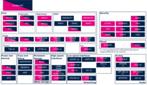
Check boxes illustrate the possible peripheral allocations supported by the OpenSTLinux BSP:
- ⬚ means that the peripheral can be assigned to the given runtime context, but this configuration is not supported in OpenSTLinux BSP.
- ☐ means that the peripheral can be assigned to the given runtime context.
- ☑ means that the peripheral is assigned by default to the given runtime context and that the peripheral is mandatory for the OpenSTLinux BSP.
- ✓ is used for system peripherals that cannot be unchecked because they are hardware connected in the device.
Refer to How to assign an internal peripheral to an execution context for more information on how to assign peripherals manually or via STM32CubeMX.
The present chapter describes STMicroelectronics recommendations or choice of implementation. Additional possibilities might be described in STM32MP13 reference manuals.
| Domain | Peripheral | Runtime allocation | Comment
| ||
|---|---|---|---|---|---|
| Instance | Cortex-A7 secure (OP-TEE) |
Cortex-A7 nonsecure (Linux) | |||
| Core/Interrupts | EXTI | EXTI | ☐ | ☐ | |
3.2.2. On STM32MP15x lines [edit | edit source]
Click on to expand or collapse the legend...
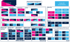
Check boxes illustrate the possible peripheral allocations supported by the OpenSTLinux BSP:
- ⬚ means that the peripheral can be assigned to the given runtime context, but this configuration is not supported in OpenSTLinux BSP.
- ☐ means that the peripheral can be assigned to the given runtime context.
- ☑ means that the peripheral is assigned by default to the given runtime context and that the peripheral is mandatory for the OpenSTLinux BSP.
- ✓ is used for system peripherals that cannot be unchecked because they are hardware connected in the device.
Refer to How to assign an internal peripheral to an execution context for more information on how to assign peripherals manually or via STM32CubeMX.
The present chapter describes STMicroelectronics recommendations or choice of implementation. Additional possiblities might be described in STM32MP15 reference manuals.
| Domain | Peripheral | Runtime allocation | Comment
| |||
|---|---|---|---|---|---|---|
| Instance | Cortex-A7 secure (OP-TEE) |
Cortex-A7 nonsecure (Linux) |
Cortex-M4 (STM32Cube) | |||
| Core/Interrupts | EXTI | EXTI | ☐ | ☐ | ☐ | Shared |
 Information Information
|
| The EXTI peripheral is not listed in STM32CubeMX peripherals list because its configuration is partly embedded in the Device tree (for all internal EXTI sources, coming from peripherals with wake up capabilities) and completed with the GPIO configuration that comes from STM32CubeMX pinout view |
The OP-TEE EXTI driver is not activated and not used by OpenSTLinux on STM32MP15x lines .
3.2.3. On STM32MP21x lines [edit | edit source]
3.2.3.1. For A35-TD flavor [edit | edit source]
Click on to expand or collapse the legend...
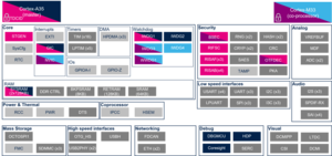
Check boxes illustrate the possible peripheral allocations supported by the OpenSTLinux BSP:
- ⬚ means that the peripheral can be assigned to the given runtime context, but this configuration is not supported in OpenSTLinux BSP.
- ☐ means that the peripheral can be assigned to the given runtime context.
- ☑ means that the peripheral is assigned by default to the given runtime context and that the peripheral is mandatory for the OpenSTLinux BSP.
- ✓ is used for system peripherals that cannot be unchecked because they are hardware connected in the device.
Refer to How to assign an internal peripheral to an execution context for more information on how to assign peripherals manually or via STM32CubeMX.
The present chapter describes STMicroelectronics recommendations or choice of implementation. Additional possibilities might be described in STM32MP21 reference manuals.
| Domain | Peripheral | Runtime allocation | Comment
| ||||
|---|---|---|---|---|---|---|---|
| Instance | Cortex-A35 secure (OP-TEE / TF-A BL31) |
Cortex-A35 nonsecure (Linux) |
Cortex-M33 secure (TF-M) |
Cortex-M33 nonsecure (STM32Cube) | |||
| Core/Interrupts | EXTI
|
EXTI1 | Shareable at internal peripheral level thanks to the RIF: see the runtime allocation per feature | ||||
| EXTI2 | Shareable at internal peripheral level thanks to the RIF: see the runtime allocation per feature | ||||||
The below table shows the possible runtime allocations for the features of the EXTI1 instance.
| Feature | Runtime allocation
|
Comment | |||
|---|---|---|---|---|---|
| Cortex-A35 secure (OP-TEE / TF-A BL31) |
Cortex-A35 nonsecure (Linux) |
Cortex-M33 secure (TF-M) |
Cortex-M33 nonsecure (STM32Cube) | ||
| EXTI1[0] | ☐OP-TEE | ☐ | ☐ | ☐ | |
| EXTI1[1] | ☐OP-TEE | ☐ | ☐ | ☐ | |
| EXTI1[2] | ☐OP-TEE | ☐ | ☐ | ☐ | |
| EXTI1[3] | ☐OP-TEE | ☐ | ☐ | ☐ | |
| EXTI1[4] | ☐OP-TEE | ☐ | ☐ | ☐ | |
| EXTI1[5] | ☐OP-TEE | ☐ | ☐ | ☐ | |
| EXTI1[6] | ☐OP-TEE | ☐ | ☐ | ☐ | |
| EXTI1[7] | ☐OP-TEE | ☐ | ☐ | ☐ | |
| EXTI1[8] | ☐OP-TEE | ☐ | ☐ | ☐ | |
| EXTI1[9] | ☐OP-TEE | ☐ | ☐ | ☐ | |
| EXTI1[10] | ☐OP-TEE | ☐ | ☐ | ☐ | |
| EXTI1[11] | ☐OP-TEE | ☐ | ☐ | ☐ | |
| EXTI1[12] | ☐OP-TEE | ☐ | ☐ | ☐ | |
| EXTI1[13] | ☐OP-TEE | ☐ | ☐ | ☐ | |
| EXTI1[14] | ☐OP-TEE | ☐ | ☐ | ☐ | |
| EXTI1[15] | ☐OP-TEE | ☐ | ☐ | ☐ | |
| PVD | ☑OP-TEE | ⬚ | ☐ | ⬚ | |
| PVM | ☑OP-TEE | ⬚ | ☐ | ⬚ | |
| RCC_MSI_FMON | ☑OP-TEE | ⬚ | ⬚ | ⬚ | |
| RCC_HSI_FMON | ☑OP-TEE | ⬚ | ☐ | ⬚ | |
| I2C1 | ☐OP-TEE | ☐ | ☐ | ☐ | |
| I2C2 | ☐OP-TEE | ☐ | ☐ | ☐ | |
| I2C3 | ☐OP-TEE | ☐ | ☐ | ☐ | |
| USART1 | ☐OP-TEE | ☐ | ☐ | ☐ | |
| USART2 | ☐OP-TEE | ☐ | ☐ | ☐ | |
| USART3 | ☐OP-TEE | ☐ | ☐ | ☐ | |
| USART6 | ☐OP-TEE | ☐ | ☐ | ☐ | |
| USART4 | ☐OP-TEE | ☐ | ☐ | ☐ | |
| USART5 | ☐OP-TEE | ☐ | ☐ | ☐ | |
| USART7 | ☐OP-TEE | ☐ | ☐ | ☐ | |
| SPI1 | ☐OP-TEE | ☐ | ☐ | ☐ | |
| SPI2 | ☐OP-TEE | ☐ | ☐ | ☐ | |
| SPI3 | ☐OP-TEE | ☐ | ☐ | ☐ | |
| SPI4 | ☐OP-TEE | ☐ | ☐ | ☐ | |
| SPI5 | ☐OP-TEE | ☐ | ☐ | ☐ | |
| SPI6 | ☐OP-TEE | ☐ | ☐ | ☐ | |
| USBH | ⬚OP-TEE | ☐ | ☐ | ☐ | |
| OTGHS | ⬚OP-TEE | ☐ | ☐ | ☐ | |
| LPTIM1 | ☐OP-TEE | ☐ | ☐ | ☐ | |
| LPTIM2 | ☐OP-TEE | ☐ | ☐ | ☐ | |
| WKUP1 wakeup | ☐OP-TEE | ☐ | ☐ | ☐ | |
| WKUP2 wakeup | ☐OP-TEE | ☐ | ☐ | ☐ | |
| WKUP3 wakeup | ☐OP-TEE | ☐ | ☐ | ☐ | |
| WKUP4 wakeup | ☐OP-TEE | ☐ | ☐ | ☐ | |
| WKUP5 wakeup | ☐OP-TEE | ☐ | ☐ | ☐ | |
| WKUP6 wakeup | ☐OP-TEE | ☐ | ☐ | ☐ | |
| IPCC1 non secure interrupt CPU1 | ✓ | ||||
| IPCC1 non secure interrupt CPU2 | ✓ | ||||
| IPCC1 secure interrupt CPU1 | ✓OP-TEE | ||||
| IPCC1 secure interrupt CPU2 | ✓ | ||||
| CPU2 SEV interrupt | ☐OP-TEE | ☐ | |||
| CPU1 SEV interrupt | ☐ | ☐ | |||
| WWDG1 Reset | ⬚OP-TEE | ☐ | |||
| ETH1_PMT wakeup | ⬚OP-TEE | ☐ | ⬚ | ☐ | |
| ETH1_SBD | ⬚OP-TEE | ☐ | ⬚ | ☐ | |
| ETH2_PMT wakeup | ⬚OP-TEE | ☐ | ⬚ | ☐ | |
| ETH2_SBD | ⬚OP-TEE | ☐ | ⬚ | ☐ | |
| DTS | ☐OP-TEE | ⬚ | ☐ | ⬚ | |
| CPU2 SYSRESETREQ local CPU2 reset | |||||
| I3C1 | ☐OP-TEE | ☐ | ☐ | ☐ | |
| I3C2 | ☐OP-TEE | ☐ | ☐ | ☐ | |
| I3C3 | ☐OP-TEE | ☐ | ☐ | ☐ | |
| HPDMA1 Channel 0 to 15 CPU1 irq | ☐OP-TEE | ☐ | |||
| HPDMA2 Channel 0 to 15 CPU1 irq | ☐OP-TEE | ☐ | |||
| HPDMA3 Channel 0 to 15 CPU1 irq | ☐OP-TEE | ☐ | |||
| HPDMA1 Channel 0 to 15 CPU2 irq | ☐ | ☐ | |||
| HPDMA2 Channel 0 to 15 CPU2 irq | ☐ | ☐ | |||
| HPDMA3 Channel 0 to 15 CPU2 irq | ☐ | ☐ | |||
The below table shows the possible runtime allocations for the features of the EXTI2 instance.
| Feature | Runtime allocation
|
Comment | |||
|---|---|---|---|---|---|
| Cortex-A35 secure (OP-TEE / TF-A BL31) |
Cortex-A35 nonsecure (Linux) |
Cortex-M33 secure (TF-M) |
Cortex-M33 nonsecure (STM32Cube) | ||
| EXTI2[0] | ☐OP-TEE | ☐ | ☐ | ☐ | |
| EXTI2[1] | ☐OP-TEE | ☐ | ☐ | ☐ | |
| EXTI2[2] | ☐OP-TEE | ☐ | ☐ | ☐ | |
| EXTI2[3] | ☐OP-TEE | ☐ | ☐ | ☐ | |
| EXTI2[4] | ☐OP-TEE | ☐ | ☐ | ☐ | |
| EXTI2[5] | ☐OP-TEE | ☐ | ☐ | ☐ | |
| EXTI2[6] | ☐OP-TEE | ☐ | ☐ | ☐ | |
| EXTI2[7] | ☐OP-TEE | ☐ | ☐ | ☐ | |
| EXTI2[8] | ☐OP-TEE | ☐ | ☐ | ☐ | |
| EXTI2[9] | ☐OP-TEE | ☐ | ☐ | ☐ | |
| EXTI2[10] | ☐OP-TEE | ☐ | ☐ | ☐ | |
| EXTI2[11] | ☐OP-TEE | ☐ | ☐ | ☐ | |
| EXTI2[12] | ☐OP-TEE | ☐ | ☐ | ☐ | |
| EXTI2[13] | ☐OP-TEE | ☐ | ☐ | ☐ | |
| EXTI2[14] | ☐OP-TEE | ☐ | ☐ | ☐ | |
| EXTI2[15] | ☐OP-TEE | ☐ | ☐ | ☐ | |
| TAMP non secure tamper CPU1 | ⬚ | ||||
| RTC global non secure Wakeup CPU1 | ✓ | ||||
| TAMP non secure tamper CPU2 | ☐ | ||||
| RTC global non secure Wakeup CPU2 | ☐ | ||||
| TAMP secure tamper CPU1 | ✓OP-TEE | ||||
| RTC global secure Wakeup CPU1 | ✓OP-TEE | ||||
| TAMP secure tamper CPU2 | ☐ | ||||
| RTC global secure Wakeup CPU2 | ☐ | ||||
| LPUART1 | ☐OP-TEE | ☐ | ☐ | ☐ | |
| LPTIM3 | ☐OP-TEE | ☐ | ☐ | ☐ | |
| LPTIM4 | ☐OP-TEE | ☐ | ☐ | ☐ | |
| LPTIM5 | ☐OP-TEE | ☐ | ☐ | ☐ | |
| IWDG1 reset | |||||
| IWDG2 reset | ☑OP-TEE | ☐ | ☐ | ||
| IWDG3 reset | ☐OP-TEE | ☐ | |||
| IWDG4 reset | ☐OP-TEE | ☐ | ☑ | ||
| IWDG1 early wake | ☑OP-TEE | ☐ | |||
| IWDG2 early wake | ☐OP-TEE | ☑ | |||
| IWDG3 early wake | ☑ | ☐ | |||
| IWDG4 early wake | ☐ | ☑ | |||
| IAC interrupt CPU1 | ✓OP-TEE | ||||
| IAC interrupt CPU2 | |||||
| VDDCPU_VD | ☐OP-TEE | ⬚ | ☐ | ☐ | |
| VDDCORE_VD | ☐OP-TEE | ⬚ | ☐ | ☐ | |
| RETRAM CRC error wakeup | |||||
| CDBGPWRUPREQ | ☐OP-TEE | ☐ | ☐ | ☐ | |
3.2.3.2. For M33-TD flavor [edit | edit source]
Click on to expand or collapse the legend...
Check boxes illustrate the possible peripheral allocations supported by the OpenSTLinux BSP:
- ⬚ means that the peripheral can be assigned to the given runtime context, but this configuration is not supported in OpenSTLinux BSP.
- ☐ means that the peripheral can be assigned to the given runtime context.
- ☑ means that the peripheral is assigned by default to the given runtime context and that the peripheral is mandatory for the OpenSTLinux BSP.
- ✓ is used for system peripherals that cannot be unchecked because they are hardware connected in the device.
Refer to How to assign an internal peripheral to an execution context for more information on how to assign peripherals manually or via STM32CubeMX.
The present chapter describes STMicroelectronics recommendations or choice of implementation. Additional possibilities might be described in STM32MP21 reference manuals.
| Domain | Peripheral | Runtime allocation | Comment
| ||||
|---|---|---|---|---|---|---|---|
| Instance | Cortex-A35 secure (OP-TEE / TF-A BL31) |
Cortex-A35 nonsecure (Linux) |
Cortex-M33 secure (TF-M) |
Cortex-M33 nonsecure (STM32Cube) | |||
| Core/Interrupts | EXTI
|
EXTI1 | Shareable at internal peripheral level thanks to the RIF: see the runtime allocation per feature | ||||
| EXTI2 | Shareable at internal peripheral level thanks to the RIF: see the runtime allocation per feature | ||||||
The below table shows the possible runtime allocations for the features of the EXTI1 instance.
| Feature | Runtime allocation
|
Comment | |||
|---|---|---|---|---|---|
| Cortex-A35 secure (OP-TEE / TF-A BL31) |
Cortex-A35 nonsecure (Linux) |
Cortex-M33 secure (TF-M) |
Cortex-M33 nonsecure (STM32Cube) | ||
| EXTI1[0] | ☐OP-TEE | ☐ | ☐ | ☐ | |
| EXTI1[1] | ☐OP-TEE | ☐ | ☐ | ☐ | |
| EXTI1[2] | ☐OP-TEE | ☐ | ☐ | ☐ | |
| EXTI1[3] | ☐OP-TEE | ☐ | ☐ | ☐ | |
| EXTI1[4] | ☐OP-TEE | ☐ | ☐ | ☐ | |
| EXTI1[5] | ☐OP-TEE | ☐ | ☐ | ☐ | |
| EXTI1[6] | ☐OP-TEE | ☐ | ☐ | ☐ | |
| EXTI1[7] | ☐OP-TEE | ☐ | ☐ | ☐ | |
| EXTI1[8] | ☐OP-TEE | ☐ | ☐ | ☐ | |
| EXTI1[9] | ☐OP-TEE | ☐ | ☐ | ☐ | |
| EXTI1[10] | ☐OP-TEE | ☐ | ☐ | ☐ | |
| EXTI1[11] | ☐OP-TEE | ☐ | ☐ | ☐ | |
| EXTI1[12] | ☐OP-TEE | ☐ | ☐ | ☐ | |
| EXTI1[13] | ☐OP-TEE | ☐ | ☐ | ☐ | |
| EXTI1[14] | ☐OP-TEE | ☐ | ☐ | ☐ | |
| EXTI1[15] | ☐OP-TEE | ☐ | ☐ | ☐ | |
| PVD | ☐OP-TEE | ⬚ | ☐ | ⬚ | |
| PVM | ☐OP-TEE | ⬚ | ☐ | ⬚ | |
| RCC_MSI_FMON | ☐OP-TEE | ⬚ | ☐ | ⬚ | |
| RCC_HSI_FMON | ☐OP-TEE | ⬚ | ☐ | ⬚ | |
| I2C1 | ☐OP-TEE | ☐ | ☐ | ☐ | |
| I2C2 | ☐OP-TEE | ☐ | ☐ | ☐ | |
| I2C3 | ☐OP-TEE | ☐ | ☐ | ☐ | |
| USART1 | ☐OP-TEE | ☐ | ☐ | ☐ | |
| USART2 | ☐OP-TEE | ☐ | ☐ | ☐ | |
| USART3 | ☐OP-TEE | ☐ | ☐ | ☐ | |
| USART6 | ☐OP-TEE | ☐ | ☐ | ☐ | |
| USART4 | ☐OP-TEE | ☐ | ☐ | ☐ | |
| USART5 | ☐OP-TEE | ☐ | ☐ | ☐ | |
| USART7 | ☐OP-TEE | ☐ | ☐ | ☐ | |
| SPI1 | ☐OP-TEE | ☐ | ☐ | ☐ | |
| SPI2 | ☐OP-TEE | ☐ | ☐ | ☐ | |
| SPI3 | ☐OP-TEE | ☐ | ☐ | ☐ | |
| SPI4 | ☐OP-TEE | ☐ | ☐ | ☐ | |
| SPI5 | ☐OP-TEE | ☐ | ☐ | ☐ | |
| SPI6 | ☐OP-TEE | ☐ | ☐ | ☐ | |
| USBH | ⬚OP-TEE | ☐ | ☐ | ☐ | |
| OTGHS | ⬚OP-TEE | ☐ | ☐ | ☐ | |
| UCPD (TBC: to remove, refman not aligned) | ⬚OP-TEE | ⬚ | ⬚ | ☐ | |
| LPTIM1 | ☐OP-TEE | ☐ | ☐ | ☐ | |
| LPTIM2 | ☐OP-TEE | ☐ | ☐ | ☐ | |
| WKUP1 wakeup | ☐OP-TEE | ☐ | ☐ | ☐ | |
| WKUP2 wakeup | ☐OP-TEE | ☐ | ☐ | ☐ | |
| WKUP3 wakeup | ☐OP-TEE | ☐ | ☐ | ☐ | |
| WKUP4 wakeup | ☐OP-TEE | ☐ | ☐ | ☐ | |
| WKUP5 wakeup | ☐OP-TEE | ☐ | ☐ | ☐ | |
| WKUP6 wakeup | ☐OP-TEE | ☐ | ☐ | ☐ | |
| IPCC1 non secure interrupt CPU1 | ✓ | ||||
| IPCC1 non secure interrupt CPU2 | ✓ | ||||
| IPCC1 secure interrupt CPU1 | ✓OP-TEE | ||||
| IPCC1 secure interrupt CPU2 | ✓ | ||||
| CPU2 SEV interrupt | ☐OP-TEE | ☐ | |||
| CPU1 SEV interrupt | ☐ | ☐ | |||
| WWDG1 Reset | ⬚OP-TEE | ☐ | |||
| ETH1_PMT wakeup | ⬚OP-TEE | ☐ | ⬚ | ☐ | |
| ETH1_SBD | ⬚OP-TEE | ☐ | ⬚ | ☐ | |
| ETH2_PMT wakeup | ⬚OP-TEE | ☐ | ⬚ | ☐ | |
| ETH2_SBD | ⬚OP-TEE | ☐ | ⬚ | ☐ | |
| DTS | ☐OP-TEE | ⬚ | ☐ | ⬚ | |
| CPU2 SYSRESETREQ local CPU2 reset | |||||
| I3C1 | ☐OP-TEE | ☐ | ☐ | ☐ | |
| I3C2 | ☐OP-TEE | ☐ | ☐ | ☐ | |
| I3C3 | ☐OP-TEE | ☐ | ☐ | ☐ | |
| HPDMA1 Channel 0 to 15 CPU1 irq | ☐OP-TEE | ☐ | |||
| HPDMA2 Channel 0 to 15 CPU1 irq | ☐OP-TEE | ☐ | |||
| HPDMA3 Channel 0 to 15 CPU1 irq | ☐OP-TEE | ☐ | |||
| HPDMA1 Channel 0 to 15 CPU2 irq | ☐ | ☐ | |||
| HPDMA2 Channel 0 to 15 CPU2 irq | ☐ | ☐ | |||
| HPDMA3 Channel 0 to 15 CPU2 irq | ☐ | ☐ | |||
The below table shows the possible runtime allocations for the features of the EXTI2 instance.
| Feature | Runtime allocation
|
Comment | |||
|---|---|---|---|---|---|
| Cortex-A35 secure (OP-TEE / TF-A BL31) |
Cortex-A35 nonsecure (Linux) |
Cortex-M33 secure (TF-M) |
Cortex-M33 nonsecure (STM32Cube) | ||
| EXTI2[0] | ☐OP-TEE | ☐ | ☐ | ☐ | |
| EXTI2[1] | ☐OP-TEE | ☐ | ☐ | ☐ | |
| EXTI2[2] | ☐OP-TEE | ☐ | ☐ | ☐ | |
| EXTI2[3] | ☐OP-TEE | ☐ | ☐ | ☐ | |
| EXTI2[4] | ☐OP-TEE | ☐ | ☐ | ☐ | |
| EXTI2[5] | ☐OP-TEE | ☐ | ☐ | ☐ | |
| EXTI2[6] | ☐OP-TEE | ☐ | ☐ | ☐ | |
| EXTI2[7] | ☐OP-TEE | ☐ | ☐ | ☐ | |
| EXTI2[8] | ☐OP-TEE | ☐ | ☐ | ☐ | |
| EXTI2[9] | ☐OP-TEE | ☐ | ☐ | ☐ | |
| EXTI2[10] | ☐OP-TEE | ☐ | ☐ | ☐ | |
| EXTI2[11] | ☐OP-TEE | ☐ | ☐ | ☐ | |
| EXTI2[12] | ☐OP-TEE | ☐ | ☐ | ☐ | |
| EXTI2[13] | ☐OP-TEE | ☐ | ☐ | ☐ | |
| EXTI2[14] | ☐OP-TEE | ☐ | ☐ | ☐ | |
| EXTI2[15] | ☐OP-TEE | ☐ | ☐ | ☐ | |
| TAMP non secure tamper CPU1 | ⬚ | ||||
| RTC global non secure Wakeup CPU1 | ✓ | ||||
| TAMP non secure tamper CPU2 | ☐ | ||||
| RTC global non secure Wakeup CPU2 | ☐ | ||||
| TAMP secure tamper CPU1 | ✓OP-TEE | ||||
| RTC global secure Wakeup CPU1 | ✓OP-TEE | ||||
| TAMP secure tamper CPU2 | ☐ | ||||
| RTC global secure Wakeup CPU2 | ☐ | ||||
| LPUART1 | ☐OP-TEE | ☐ | ☐ | ☐ | |
| LPTIM3 | ☐OP-TEE | ☐ | ☐ | ☐ | |
| LPTIM4 | ☐OP-TEE | ☐ | ☐ | ☐ | |
| LPTIM5 | ☐OP-TEE | ☐ | ☐ | ☐ | |
| IWDG1 reset | ☐ | ☐ | |||
| IWDG2 reset | ☑OP-TEE | ☐ | ☐ | ||
| IWDG3 reset | |||||
| IWDG4 reset | ☐OP-TEE | ☐ | ☐ | ||
| IWDG1 early wake | ☑OP-TEE | ☐ | |||
| IWDG2 early wake | ☐OP-TEE | ☐ | |||
| IWDG3 early wake | ☐ | ☐ | |||
| IWDG4 early wake | ☐ | ☐ | |||
| IAC interrupt CPU1 | |||||
| IAC interrupt CPU2 | ✓ | ||||
| VDDCPU_VD | ☐OP-TEE | ⬚ | ☐ | ☐ | |
| VDDCORE_VD | ☐OP-TEE | ⬚ | ☐ | ☐ | |
| RETRAM CRC error wakeup | |||||
| CDBGPWRUPREQ | ☐OP-TEE | ☐ | ☐ | ☐ | |
3.2.4. On STM32MP23x lines [edit | edit source]
3.2.4.1. For A35-TD flavor [edit | edit source]
Click on to expand or collapse the legend...
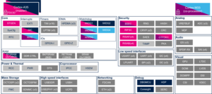
Check boxes illustrate the possible peripheral allocations supported by the OpenSTLinux BSP:
- ⬚ means that the peripheral can be assigned to the given runtime context, but this configuration is not supported in OpenSTLinux BSP.
- ☐ means that the peripheral can be assigned to the given runtime context.
- ☑ means that the peripheral is assigned by default to the given runtime context and that the peripheral is mandatory for the OpenSTLinux BSP.
- ✓ is used for system peripherals that cannot be unchecked because they are hardware connected in the device.
Refer to How to assign an internal peripheral to an execution context for more information on how to assign peripherals manually or via STM32CubeMX.
The present chapter describes STMicroelectronics recommendations or choice of implementation. Additional possibilities might be described in STM32MP23 reference manuals.
| Domain | Peripheral | Runtime allocation | Comment
| ||||
|---|---|---|---|---|---|---|---|
| Instance | Cortex-A35 secure (OP-TEE / TF-A BL31) |
Cortex-A35 nonsecure (Linux) |
Cortex-M33 secure (TF-M) |
Cortex-M33 nonsecure (STM32Cube) | |||
| Core/Interrupts | EXTI
|
EXTI1 | Shareable at internal peripheral level thanks to the RIF: see the runtime allocation per feature | ||||
| EXTI2 | Shareable at internal peripheral level thanks to the RIF: see the runtime allocation per feature | ||||||
The below table shows the possible runtime allocations for the features of the EXTI1 instance.
| Feature | Runtime allocation
|
Comment | |||
|---|---|---|---|---|---|
| Cortex-A35 secure (OP-TEE / TF-A BL31) |
Cortex-A35 nonsecure (Linux) |
Cortex-M33 secure (TF-M) |
Cortex-M33 nonsecure (STM32Cube) | ||
| EXTI1[0] | ☐OP-TEE | ☐ | ☐ | ☐ | |
| EXTI1[1] | ☐OP-TEE | ☐ | ☐ | ☐ | |
| EXTI1[2] | ☐OP-TEE | ☐ | ☐ | ☐ | |
| EXTI1[3] | ☐OP-TEE | ☐ | ☐ | ☐ | |
| EXTI1[4] | ☐OP-TEE | ☐ | ☐ | ☐ | |
| EXTI1[5] | ☐OP-TEE | ☐ | ☐ | ☐ | |
| EXTI1[6] | ☐OP-TEE | ☐ | ☐ | ☐ | |
| EXTI1[7] | ☐OP-TEE | ☐ | ☐ | ☐ | |
| EXTI1[8] | ☐OP-TEE | ☐ | ☐ | ☐ | |
| EXTI1[9] | ☐OP-TEE | ☐ | ☐ | ☐ | |
| EXTI1[10] | ☐OP-TEE | ☐ | ☐ | ☐ | |
| EXTI1[11] | ☐OP-TEE | ☐ | ☐ | ☐ | |
| EXTI1[12] | ☐OP-TEE | ☐ | ☐ | ☐ | |
| EXTI1[13] | ☐OP-TEE | ☐ | ☐ | ☐ | |
| EXTI1[14] | ☐OP-TEE | ☐ | ☐ | ☐ | |
| EXTI1[15] | ☐OP-TEE | ☐ | ☐ | ☐ | |
| PVD | ☑OP-TEE | ⬚ | ☐ | ⬚ | |
| PVM | ☑OP-TEE | ⬚ | ☐ | ⬚ | |
| VDDGPU_VD | ☑OP-TEE | ⬚ | ⬚ | ⬚ | |
| RCC_HSI_FMON | ☑OP-TEE | ⬚ | ☐ | ⬚ | |
| I2C1 | ☐OP-TEE | ☐ | ☐ | ☐ | |
| I2C2 | ☐OP-TEE | ☐ | ☐ | ☐ | |
| I2C3 | |||||
| I2C4 | |||||
| I2C5 | |||||
| USART1 | ☐OP-TEE | ☐ | ☐ | ☐ | |
| USART2 | ☐OP-TEE | ☐ | ☐ | ☐ | |
| USART3 | ☐OP-TEE | ☐ | ☐ | ☐ | |
| USART6 | ☐OP-TEE | ☐ | ☐ | ☐ | |
| USART4 | ☐OP-TEE | ☐ | ☐ | ☐ | |
| USART5 | ☐OP-TEE | ☐ | ☐ | ☐ | |
| USART7 | ☐OP-TEE | ☐ | ☐ | ☐ | |
| USART8 | |||||
| USART9 | |||||
| SPI1 | ☐OP-TEE | ☐ | ☐ | ☐ | |
| SPI2 | ☐OP-TEE | ☐ | ☐ | ☐ | |
| SPI3 | ☐OP-TEE | ☐ | ☐ | ☐ | |
| SPI4 | ☐OP-TEE | ☐ | ☐ | ☐ | |
| SPI5 | ☐OP-TEE | ☐ | ☐ | ☐ | |
| SPI6 | |||||
| SPI7 | |||||
| USBH | ⬚OP-TEE | ☐ | ☐ | ☐ | |
| USB3DR | ⬚OP-TEE | ☐ | ☐ | ☐ | |
| COMBOPHY | |||||
| UCPD | ⬚OP-TEE | ⬚ | ⬚ | ☑ | |
| LPTIM1 | ☐OP-TEE | ☐ | ☐ | ☐ | |
| LPTIM2 | ☐OP-TEE | ☐ | ☐ | ☐ | |
| I2C6 | |||||
| I2C7 | ☐OP-TEE | ☐ | ☐ | ☐ | |
| WKUP1 wakeup | ☐OP-TEE | ☐ | ☐ | ☐ | |
| WKUP2 wakeup | ☐OP-TEE | ☐ | ☐ | ☐ | |
| WKUP3 wakeup | ☐OP-TEE | ☐ | ☐ | ☐ | |
| WKUP4 wakeup | ☐OP-TEE | ☐ | ☐ | ☐ | |
| WKUP5 wakeup | ☐OP-TEE | ☐ | ☐ | ☐ | |
| WKUP6 wakeup | ☐OP-TEE | ☐ | ☐ | ☐ | |
| IPCC1 non secure interrupt CPU1 | ✓ | ||||
| IPCC1 non secure interrupt CPU2 | ✓ | ||||
| IPCC1 secure interrupt CPU1 | ✓OP-TEE | ||||
| IPCC1 secure interrupt CPU2 | ✓ | ||||
| CPU2 SEV interrupt | ☐OP-TEE | ☐ | |||
| CPU1 SEV interrupt | ☐ | ☐ | |||
| WWDG1 Reset | ⬚OP-TEE | ☐ | |||
| ETH1_PMT wakeup | ⬚OP-TEE | ☐ | ⬚ | ☐ | |
| ETH1_SBD | ⬚OP-TEE | ☐ | ⬚ | ☐ | |
| ETH2_PMT wakeup | ⬚OP-TEE | ☐ | ⬚ | ☐ | |
| ETH2_SBD | ⬚OP-TEE | ☐ | ⬚ | ☐ | |
| DTS | ☐OP-TEE | ⬚ | ☐ | ⬚ | |
| CPU2 SYSRESETREQ local CPU2 reset | |||||
| I3C1 | ☐OP-TEE | ☐ | ☐ | ☐ | |
| I3C2 | ☐OP-TEE | ☐ | ☐ | ☐ | |
| I3C3 | |||||
| HPDMA1 Channel 0 to 15 CPU1 irq | ☐OP-TEE | ☐ | |||
| HPDMA2 Channel 0 to 15 CPU1 irq | ☐OP-TEE | ☐ | |||
| HPDMA3 Channel 0 to 15 CPU1 irq | ☐OP-TEE | ☐ | |||
| HPDMA1 Channel 0 to 15 CPU2 irq | ☐ | ☐ | |||
| HPDMA2 Channel 0 to 15 CPU2 irq | ☐ | ☐ | |||
| HPDMA3 Channel 0 to 15 CPU2 irq | ☐ | ☐ | |||
| UCPD VBUS DETECT | ⬚OP-TEE | ⬚ | ⬚ | ☑ | |
| UCPD VBUS VSAFE5V | ⬚OP-TEE | ⬚ | ⬚ | ☑ | |
The below table shows the possible runtime allocations for the features of the EXTI2 instance.
| Feature | Runtime allocation
|
Comment | |||
|---|---|---|---|---|---|
| Cortex-A35 secure (OP-TEE / TF-A BL31) |
Cortex-A35 nonsecure (Linux) |
Cortex-M33 secure (TF-M) |
Cortex-M33 nonsecure (STM32Cube) | ||
| EXTI2[0] | ☐OP-TEE | ☐ | ☐ | ☐ | |
| EXTI2[1] | ☐OP-TEE | ☐ | ☐ | ☐ | |
| EXTI2[2] | ☐OP-TEE | ☐ | ☐ | ☐ | |
| EXTI2[3] | ☐OP-TEE | ☐ | ☐ | ☐ | |
| EXTI2[4] | ☐OP-TEE | ☐ | ☐ | ☐ | |
| EXTI2[5] | ☐OP-TEE | ☐ | ☐ | ☐ | |
| EXTI2[6] | ☐OP-TEE | ☐ | ☐ | ☐ | |
| EXTI2[7] | ☐OP-TEE | ☐ | ☐ | ☐ | |
| EXTI2[8] | ☐OP-TEE | ☐ | ☐ | ☐ | |
| EXTI2[9] | ☐OP-TEE | ☐ | ☐ | ☐ | |
| EXTI2[10] | ☐OP-TEE | ☐ | ☐ | ☐ | |
| EXTI2[11] | ☐OP-TEE | ☐ | ☐ | ☐ | |
| EXTI2[12] | ☐OP-TEE | ☐ | ☐ | ☐ | |
| EXTI2[13] | ☐OP-TEE | ☐ | ☐ | ☐ | |
| EXTI2[14] | ☐OP-TEE | ☐ | ☐ | ☐ | |
| EXTI2[15] | ☐OP-TEE | ☐ | ☐ | ☐ | |
| TAMP non secure tamper CPU1 | ⬚ | ||||
| RTC global non secure Wakeup CPU1 | ✓ | ||||
| TAMP non secure tamper CPU2 | ☐ | ||||
| RTC global non secure Wakeup CPU2 | ☐ | ||||
| TAMP non secure tamper CPU3 | |||||
| TAMP secure tamper CPU1 | ✓OP-TEE | ||||
| RTC global secure Wakeup CPU1 | ✓OP-TEE | ||||
| TAMP secure tamper CPU2 | ☐ | ||||
| RTC global secure Wakeup CPU2 | ☐ | ||||
| I2C8 | ☐OP-TEE | ☐ | ☐ | ☐ | |
| LPUART1 | ☐OP-TEE | ☐ | ☐ | ☐ | |
| SPI8 | ☐OP-TEE | ☐ | ☐ | ☐ | |
| LPTIM3 | ☐OP-TEE | ☐ | ☐ | ☐ | |
| LPTIM4 | ☐OP-TEE | ☐ | ☐ | ☐ | |
| LPTIM5 | ☐OP-TEE | ☐ | ☐ | ☐ | |
| ADF1 | |||||
| IPCC2 non secure interrupt CPU1 | ☑ | ||||
| IPCC2 non secure interrupt CPU2 | ☑ | ||||
| IPCC2 non secure interrupt CPU3 | |||||
| IPCC2 secure interrupt CPU1 | ☑OP-TEE | ||||
| IPCC2 secure interrupt CPU2 | ☑ | ||||
| HSEM1 non secure interrupt | ☑ | ||||
| HSEM2 non secure interrupt | ☑ | ||||
| HSEM3 non secure interrupt | |||||
| HSEM1 secure interrupt | ☑OP-TEE | ||||
| HSEM2 secure interrupt | ☑ | ||||
| WWDG2 reset | ☐OP-TEE | ☐ | ☐ | ☐ | |
| IWDG1 reset | |||||
| IWDG2 reset | ☑OP-TEE | ☐ | ☐ | ||
| IWDG3 reset | ☐OP-TEE | ☐ | |||
| IWDG4 reset | ☐OP-TEE | ☐ | ☑ | ||
| IWDG5 reset | ☐OP-TEE | ☐ | ☐ | ☐ | |
| IWDG1 early wake | ☑OP-TEE | ☐ | |||
| IWDG2 early wake | ☐OP-TEE | ☑ | |||
| IWDG3 early wake | ☑ | ☐ | |||
| IWDG4 early wake | ☐ | ☑ | |||
| IWDG5 early wake | |||||
| CM33 SEV interrupt to CPU3 | |||||
| CA35 SEV interrupt to CPU3 | |||||
| CM0 SEV interrupt | |||||
| IAC interrupt CPU1 | ✓OP-TEE | ||||
| IAC interrupt CPU2 | |||||
| VDDCPU_VD | ☐OP-TEE | ⬚ | ☐ | ☐ | |
| VDDCORE_VD | ☐OP-TEE | ⬚ | ☐ | ☐ | |
| RETRAM CRC error wakeup | |||||
| lpdma_ch0123_cpu1_irq | |||||
| lpdma_ch0123_cpu2_irq | |||||
| lpdma_ch0123_cpu3_irq | |||||
| I3C4 | ☐OP-TEE | ☐ | ☐ | ☐ | |
| CDBGPWRUPREQ | ☐OP-TEE | ☐ | ☐ | ☐ | |
3.2.4.2. For M33-TD flavor [edit | edit source]
Click on to expand or collapse the legend...
Check boxes illustrate the possible peripheral allocations supported by the OpenSTLinux BSP:
- ⬚ means that the peripheral can be assigned to the given runtime context, but this configuration is not supported in OpenSTLinux BSP.
- ☐ means that the peripheral can be assigned to the given runtime context.
- ☑ means that the peripheral is assigned by default to the given runtime context and that the peripheral is mandatory for the OpenSTLinux BSP.
- ✓ is used for system peripherals that cannot be unchecked because they are hardware connected in the device.
Refer to How to assign an internal peripheral to an execution context for more information on how to assign peripherals manually or via STM32CubeMX.
The present chapter describes STMicroelectronics recommendations or choice of implementation. Additional possibilities might be described in STM32MP23 reference manuals.
| Domain | Peripheral | Runtime allocation | Comment
| ||||
|---|---|---|---|---|---|---|---|
| Instance | Cortex-A35 secure (OP-TEE / TF-A BL31) |
Cortex-A35 nonsecure (Linux) |
Cortex-M33 secure (TF-M) |
Cortex-M33 nonsecure (STM32Cube) | |||
| Core/Interrupts | EXTI
|
EXTI1 | Shareable at internal peripheral level thanks to the RIF: see the runtime allocation per feature | ||||
| EXTI2 | Shareable at internal peripheral level thanks to the RIF: see the runtime allocation per feature | ||||||
The below table shows the possible runtime allocations for the features of the EXTI1 instance.
| Feature | Runtime allocation
|
Comment | |||
|---|---|---|---|---|---|
| Cortex-A35 secure (OP-TEE / TF-A BL31) |
Cortex-A35 nonsecure (Linux) |
Cortex-M33 secure (TF-M) |
Cortex-M33 nonsecure (STM32Cube) | ||
| EXTI1[0] | ☐OP-TEE | ☐ | ☐ | ☐ | |
| EXTI1[1] | ☐OP-TEE | ☐ | ☐ | ☐ | |
| EXTI1[2] | ☐OP-TEE | ☐ | ☐ | ☐ | |
| EXTI1[3] | ☐OP-TEE | ☐ | ☐ | ☐ | |
| EXTI1[4] | ☐OP-TEE | ☐ | ☐ | ☐ | |
| EXTI1[5] | ☐OP-TEE | ☐ | ☐ | ☐ | |
| EXTI1[6] | ☐OP-TEE | ☐ | ☐ | ☐ | |
| EXTI1[7] | ☐OP-TEE | ☐ | ☐ | ☐ | |
| EXTI1[8] | ☐OP-TEE | ☐ | ☐ | ☐ | |
| EXTI1[9] | ☐OP-TEE | ☐ | ☐ | ☐ | |
| EXTI1[10] | ☐OP-TEE | ☐ | ☐ | ☐ | |
| EXTI1[11] | ☐OP-TEE | ☐ | ☐ | ☐ | |
| EXTI1[12] | ☐OP-TEE | ☐ | ☐ | ☐ | |
| EXTI1[13] | ☐OP-TEE | ☐ | ☐ | ☐ | |
| EXTI1[14] | ☐OP-TEE | ☐ | ☐ | ☐ | |
| EXTI1[15] | ☐OP-TEE | ☐ | ☐ | ☐ | |
| PVD | ☐OP-TEE | ⬚ | ☐ | ⬚ | |
| PVM | ☐OP-TEE | ⬚ | ☐ | ⬚ | |
| VDDGPU_VD | ☐OP-TEE | ⬚ | ☐ | ⬚ | |
| RCC_HSI_FMON | ☐OP-TEE | ⬚ | ☐ | ⬚ | |
| I2C1 | ☐OP-TEE | ☐ | ☐ | ☐ | |
| I2C2 | ☐OP-TEE | ☐ | ☐ | ☐ | |
| USART1 | ☐OP-TEE | ☐ | ☐ | ☐ | |
| USART2 | ☐OP-TEE | ☐ | ☐ | ☐ | |
| USART3 | ☐OP-TEE | ☐ | ☐ | ☐ | |
| USART6 | ☐OP-TEE | ☐ | ☐ | ☐ | |
| USART4 | ☐OP-TEE | ☐ | ☐ | ☐ | |
| USART5 | ☐OP-TEE | ☐ | ☐ | ☐ | |
| USART7 | ☐OP-TEE | ☐ | ☐ | ☐ | |
| SPI1 | ☐OP-TEE | ☐ | ☐ | ☐ | |
| SPI2 | ☐OP-TEE | ☐ | ☐ | ☐ | |
| SPI3 | ☐OP-TEE | ☐ | ☐ | ☐ | |
| SPI4 | ☐OP-TEE | ☐ | ☐ | ☐ | |
| SPI5 | ☐OP-TEE | ☐ | ☐ | ☐ | |
| USBH | ⬚OP-TEE | ☐ | ☐ | ☐ | |
| USB3DR | ⬚OP-TEE | ☐ | ☐ | ☐ | |
| UCPD | ⬚OP-TEE | ⬚ | ⬚ | ☐ | |
| LPTIM1 | ☐OP-TEE | ☐ | ☐ | ☐ | |
| LPTIM2 | ☐OP-TEE | ☐ | ☐ | ☐ | |
| I2C7 | ☐OP-TEE | ☐ | ☐ | ☐ | |
| WKUP1 wakeup | ☐OP-TEE | ☐ | ☐ | ☐ | |
| WKUP2 wakeup | ☐OP-TEE | ☐ | ☐ | ☐ | |
| WKUP3 wakeup | ☐OP-TEE | ☐ | ☐ | ☐ | |
| WKUP4 wakeup | ☐OP-TEE | ☐ | ☐ | ☐ | |
| WKUP5 wakeup | ☐OP-TEE | ☐ | ☐ | ☐ | |
| WKUP6 wakeup | ☐OP-TEE | ☐ | ☐ | ☐ | |
| IPCC1 non secure interrupt CPU1 | ✓ | ||||
| IPCC1 non secure interrupt CPU2 | ✓ | ||||
| IPCC1 secure interrupt CPU1 | ✓OP-TEE | ||||
| IPCC1 secure interrupt CPU2 | ✓ | ||||
| CPU2 SEV interrupt | ☐OP-TEE | ☐ | |||
| CPU1 SEV interrupt | ☐ | ☐ | |||
| WWDG1 Reset | ⬚OP-TEE | ☐ | |||
| ETH1_PMT wakeup | ⬚OP-TEE | ☐ | ⬚ | ☐ | |
| ETH1_SBD | ⬚OP-TEE | ☐ | ⬚ | ☐ | |
| ETH2_PMT wakeup | ⬚OP-TEE | ☐ | ⬚ | ☐ | |
| ETH2_SBD | ⬚OP-TEE | ☐ | ⬚ | ☐ | |
| DTS | ☐OP-TEE | ⬚ | ☐ | ⬚ | |
| CPU2 SYSRESETREQ local CPU2 reset | |||||
| I3C1 | ☐OP-TEE | ☐ | ☐ | ☐ | |
| I3C2 | ☐OP-TEE | ☐ | ☐ | ☐ | |
| HPDMA1 Channel 0 to 15 CPU1 irq | ☐OP-TEE | ☐ | |||
| HPDMA2 Channel 0 to 15 CPU1 irq | ☐OP-TEE | ☐ | |||
| HPDMA3 Channel 0 to 15 CPU1 irq | ☐OP-TEE | ☐ | |||
| HPDMA1 Channel 0 to 15 CPU2 irq | ☐ | ☐ | |||
| HPDMA2 Channel 0 to 15 CPU2 irq | ☐ | ☐ | |||
| HPDMA3 Channel 0 to 15 CPU2 irq | ☐ | ☐ | |||
| UCPD VBUS DETECT | ⬚OP-TEE | ⬚ | ⬚ | ☐ | |
| UCPD VBUS VSAFE5V | ⬚OP-TEE | ⬚ | ⬚ | ☐ | |
The below table shows the possible runtime allocations for the features of the EXTI2 instance.
| Feature | Runtime allocation
|
Comment | |||
|---|---|---|---|---|---|
| Cortex-A35 secure (OP-TEE / TF-A BL31) |
Cortex-A35 nonsecure (Linux) |
Cortex-M33 secure (TF-M) |
Cortex-M33 nonsecure (STM32Cube) | ||
| EXTI2[0] | ☐OP-TEE | ☐ | ☐ | ☐ | |
| EXTI2[1] | ☐OP-TEE | ☐ | ☐ | ☐ | |
| EXTI2[2] | ☐OP-TEE | ☐ | ☐ | ☐ | |
| EXTI2[3] | ☐OP-TEE | ☐ | ☐ | ☐ | |
| EXTI2[4] | ☐OP-TEE | ☐ | ☐ | ☐ | |
| EXTI2[5] | ☐OP-TEE | ☐ | ☐ | ☐ | |
| EXTI2[6] | ☐OP-TEE | ☐ | ☐ | ☐ | |
| EXTI2[7] | ☐OP-TEE | ☐ | ☐ | ☐ | |
| EXTI2[8] | ☐OP-TEE | ☐ | ☐ | ☐ | |
| EXTI2[9] | ☐OP-TEE | ☐ | ☐ | ☐ | |
| EXTI2[10] | ☐OP-TEE | ☐ | ☐ | ☐ | |
| EXTI2[11] | ☐OP-TEE | ☐ | ☐ | ☐ | |
| EXTI2[12] | ☐OP-TEE | ☐ | ☐ | ☐ | |
| EXTI2[13] | ☐OP-TEE | ☐ | ☐ | ☐ | |
| EXTI2[14] | ☐OP-TEE | ☐ | ☐ | ☐ | |
| EXTI2[15] | ☐OP-TEE | ☐ | ☐ | ☐ | |
| TAMP non secure tamper CPU1 | ⬚ | ||||
| RTC global non secure Wakeup CPU1 | ✓ | ||||
| TAMP non secure tamper CPU2 | ☐ | ||||
| RTC global non secure Wakeup CPU2 | ☐ | ||||
| TAMP non secure tamper CPU3 | |||||
| TAMP secure tamper CPU1 | ✓OP-TEE | ||||
| RTC global secure Wakeup CPU1 | ✓OP-TEE | ||||
| TAMP secure tamper CPU2 | ☐ | ||||
| RTC global secure Wakeup CPU2 | ☐ | ||||
| I2C8 | ☐OP-TEE | ☐ | ☐ | ☐ | |
| LPUART1 | ☐OP-TEE | ☐ | ☐ | ☐ | |
| SPI8 | ☐OP-TEE | ☐ | ☐ | ☐ | |
| LPTIM3 | ☐OP-TEE | ☐ | ☐ | ☐ | |
| LPTIM4 | ☐OP-TEE | ☐ | ☐ | ☐ | |
| LPTIM5 | ☐OP-TEE | ☐ | ☐ | ☐ | |
| IPCC2 non secure interrupt CPU1 | ☐ | ||||
| IPCC2 non secure interrupt CPU2 | ☐ | ||||
| IPCC2 non secure interrupt CPU3 | |||||
| IPCC2 secure interrupt CPU1 | ☑OP-TEE | ||||
| IPCC2 secure interrupt CPU2 | ☐ | ||||
| HSEM1 non secure interrupt | ☐ | ||||
| HSEM2 non secure interrupt | ☐ | ||||
| HSEM3 non secure interrupt | |||||
| HSEM1 secure interrupt | ☑OP-TEE | ||||
| HSEM2 secure interrupt | ☐ | ||||
| WWDG2 reset | ☐OP-TEE | ☐ | ☐ | ☐ | |
| IWDG1 reset | ☐ | ☐ | |||
| IWDG2 reset | ☑OP-TEE | ☐ | ☐ | ||
| IWDG3 reset | |||||
| IWDG4 reset | ☐OP-TEE | ☐ | ☐ | ||
| IWDG1 early wake | ☑OP-TEE | ☐ | |||
| IWDG2 early wake | ☐OP-TEE | ☐ | |||
| IWDG3 early wake | ☐ | ☐ | |||
| IWDG4 early wake | ☐ | ☐ | |||
| CM33 SEV interrupt to CPU3 | |||||
| CA35 SEV interrupt to CPU3 | |||||
| IAC interrupt CPU1 | |||||
| IAC interrupt CPU2 | ✓ | ||||
| VDDCPU_VD | ☐OP-TEE | ⬚ | ☐ | ☐ | |
| VDDCORE_VD | ☐OP-TEE | ⬚ | ☐ | ☐ | |
| RETRAM CRC error wakeup | |||||
| I3C4 | ☐OP-TEE | ☐ | ☐ | ☐ | |
| CDBGPWRUPREQ | ☐OP-TEE | ☐ | ☐ | ☐ | |
3.2.5. On STM32MP25x lines [edit | edit source]
3.2.5.1. For A35-TD flavor [edit | edit source]
Click on to expand or collapse the legend...
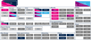


Check boxes illustrate the possible peripheral allocations supported by the OpenSTLinux BSP:
- ⬚ means that the peripheral can be assigned to the given runtime context, but this configuration is not supported in OpenSTLinux BSP.
- ☐ means that the peripheral can be assigned to the given runtime context.
- ☑ means that the peripheral is assigned by default to the given runtime context and that the peripheral is mandatory for the OpenSTLinux BSP.
- ✓ is used for system peripherals that cannot be unchecked because they are hardware connected in the device.
Refer to How to assign an internal peripheral to an execution context for more information on how to assign peripherals manually or via STM32CubeMX.
The present chapter describes STMicroelectronics recommendations or choice of implementation. Additional possibilities might be described in STM32MP25 reference manuals.
| Domain | Peripheral | Runtime allocation | Comment
| |||||
|---|---|---|---|---|---|---|---|---|
| Instance | Cortex-A35 secure (OP-TEE / TF-A BL31) |
Cortex-A35 nonsecure (Linux) |
Cortex-M33 secure (TF-M) |
Cortex-M33 nonsecure (STM32Cube) |
Cortex-M0+ (STM32Cube) | |||
| Core/Interrupts | EXTI
|
EXTI1 | Shareable at internal peripheral level thanks to the RIF: see the runtime allocation per feature | |||||
| EXTI2 | Shareable at internal peripheral level thanks to the RIF: see the runtime allocation per feature | |||||||
The below table shows the possible runtime allocations for the features of the EXTI1 instance.
| Feature | Runtime allocation
|
Comment | ||||
|---|---|---|---|---|---|---|
| Cortex-A35 secure (OP-TEE / TF-A BL31) |
Cortex-A35 nonsecure (Linux) |
Cortex-M33 secure (TF-M) |
Cortex-M33 nonsecure (STM32Cube) |
Cortex-M0+ (STM32Cube) | ||
| EXTI1[0] | ☐OP-TEE | ☐ | ☐ | ☐ | ||
| EXTI1[1] | ☐OP-TEE | ☐ | ☐ | ☐ | ||
| EXTI1[2] | ☐OP-TEE | ☐ | ☐ | ☐ | ||
| EXTI1[3] | ☐OP-TEE | ☐ | ☐ | ☐ | ||
| EXTI1[4] | ☐OP-TEE | ☐ | ☐ | ☐ | ||
| EXTI1[5] | ☐OP-TEE | ☐ | ☐ | ☐ | ||
| EXTI1[6] | ☐OP-TEE | ☐ | ☐ | ☐ | ||
| EXTI1[7] | ☐OP-TEE | ☐ | ☐ | ☐ | ||
| EXTI1[8] | ☐OP-TEE | ☐ | ☐ | ☐ | ||
| EXTI1[9] | ☐OP-TEE | ☐ | ☐ | ☐ | ||
| EXTI1[10] | ☐OP-TEE | ☐ | ☐ | ☐ | ||
| EXTI1[11] | ☐OP-TEE | ☐ | ☐ | ☐ | ||
| EXTI1[12] | ☐OP-TEE | ☐ | ☐ | ☐ | ||
| EXTI1[13] | ☐OP-TEE | ☐ | ☐ | ☐ | ||
| EXTI1[14] | ☐OP-TEE | ☐ | ☐ | ☐ | ||
| EXTI1[15] | ☐OP-TEE | ☐ | ☐ | ☐ | ||
| PVD | ☑OP-TEE | ⬚ | ☐ | ⬚ | ||
| PVM | ☑OP-TEE | ⬚ | ☐ | ⬚ | ||
| VDDGPU_VD | ☑OP-TEE | ⬚ | ⬚ | ⬚ | ||
| RCC_HSI_FMON | ☑OP-TEE | ⬚ | ☐ | ⬚ | ||
| I2C1 | ☐OP-TEE | ☐ | ☐ | ☐ | ||
| I2C2 | ☐OP-TEE | ☐ | ☐ | ☐ | ||
| I2C3 | ☐OP-TEE | ☐ | ☐ | ☐ | ||
| I2C4 | ☐OP-TEE | ☐ | ☐ | ☐ | ||
| I2C5 | ☐OP-TEE | ☐ | ☐ | ☐ | ||
| USART1 | ☐OP-TEE | ☐ | ☐ | ☐ | ||
| USART2 | ☐OP-TEE | ☐ | ☐ | ☐ | ||
| USART3 | ☐OP-TEE | ☐ | ☐ | ☐ | ||
| USART6 | ☐OP-TEE | ☐ | ☐ | ☐ | ||
| USART4 | ☐OP-TEE | ☐ | ☐ | ☐ | ||
| USART5 | ☐OP-TEE | ☐ | ☐ | ☐ | ||
| USART7 | ☐OP-TEE | ☐ | ☐ | ☐ | ||
| USART8 | ☐OP-TEE | ☐ | ☐ | ☐ | ||
| USART9 | ☐OP-TEE | ☐ | ☐ | ☐ | ||
| SPI1 | ☐OP-TEE | ☐ | ☐ | ☐ | ||
| SPI2 | ☐OP-TEE | ☐ | ☐ | ☐ | ||
| SPI3 | ☐OP-TEE | ☐ | ☐ | ☐ | ||
| SPI4 | ☐OP-TEE | ☐ | ☐ | ☐ | ||
| SPI5 | ☐OP-TEE | ☐ | ☐ | ☐ | ||
| SPI6 | ☐OP-TEE | ☐ | ☐ | ☐ | ||
| SPI7 | ☐OP-TEE | ☐ | ☐ | ☐ | ||
| USBH | ⬚OP-TEE | ☐ | ☐ | ☐ | ||
| USB3DR | ⬚OP-TEE | ☐ | ☐ | ☐ | ||
| COMBOPHY | ⬚OP-TEE | ☑ | ⬚ | ⬚ | ||
| UCPD | ⬚OP-TEE | ⬚ | ⬚ | ☑ | ||
| LPTIM1 | ☐OP-TEE | ☐ | ☐ | ☐ | ||
| LPTIM2 | ☐OP-TEE | ☐ | ☐ | ☐ | ||
| I2C6 | ☐OP-TEE | ☐ | ☐ | ☐ | ||
| I2C7 | ☐OP-TEE | ☐ | ☐ | ☐ | ||
| WKUP1 wakeup | ☐OP-TEE | ☐ | ☐ | ☐ | ||
| WKUP2 wakeup | ☐OP-TEE | ☐ | ☐ | ☐ | ||
| WKUP3 wakeup | ☐OP-TEE | ☐ | ☐ | ☐ | ||
| WKUP4 wakeup | ☐OP-TEE | ☐ | ☐ | ☐ | ||
| WKUP5 wakeup | ☐OP-TEE | ☐ | ☐ | ☐ | ||
| WKUP6 wakeup | ☐OP-TEE | ☐ | ☐ | ☐ | ||
| IPCC1 non secure interrupt CPU1 | ✓ | |||||
| IPCC1 non secure interrupt CPU2 | ✓ | |||||
| IPCC1 secure interrupt CPU1 | ✓OP-TEE | |||||
| IPCC1 secure interrupt CPU2 | ✓ | |||||
| CPU2 SEV interrupt | ☐OP-TEE | ☐ | ||||
| CPU1 SEV interrupt | ☐ | ☐ | ||||
| WWDG1 Reset | ⬚OP-TEE | ☐ | ||||
| ETH1_PMT wakeup | ⬚OP-TEE | ☐ | ⬚ | ☐ | ||
| ETH1_SBD | ⬚OP-TEE | ☐ | ⬚ | ☐ | ||
| ETH2_PMT wakeup | ⬚OP-TEE | ☐ | ⬚ | ☐ | ||
| ETH2_SBD | ⬚OP-TEE | ☐ | ⬚ | ☐ | ||
| DTS | ☐OP-TEE | ⬚ | ☐ | ⬚ | ||
| CPU2 SYSRESETREQ local CPU2 reset | ||||||
| I3C1 | ☐OP-TEE | ☐ | ☐ | ☐ | ||
| I3C2 | ☐OP-TEE | ☐ | ☐ | ☐ | ||
| I3C3 | ☐OP-TEE | ☐ | ☐ | ☐ | ||
| HPDMA1 Channel 0 to 15 CPU1 irq | ☐OP-TEE | ☐ | ||||
| HPDMA2 Channel 0 to 15 CPU1 irq | ☐OP-TEE | ☐ | ||||
| HPDMA3 Channel 0 to 15 CPU1 irq | ☐OP-TEE | ☐ | ||||
| HPDMA1 Channel 0 to 15 CPU2 irq | ☐ | ☐ | ||||
| HPDMA2 Channel 0 to 15 CPU2 irq | ☐ | ☐ | ||||
| HPDMA3 Channel 0 to 15 CPU2 irq | ☐ | ☐ | ||||
| UCPD VBUS DETECT | ⬚OP-TEE | ⬚ | ⬚ | ☑ | ||
| UCPD VBUS VSAFE5V | ⬚OP-TEE | ⬚ | ⬚ | ☑ | ||
The below table shows the possible runtime allocations for the features of the EXTI2 instance.
| Feature | Runtime allocation
|
Comment | ||||
|---|---|---|---|---|---|---|
| Cortex-A35 secure (OP-TEE / TF-A BL31) |
Cortex-A35 nonsecure (Linux) |
Cortex-M33 secure (TF-M) |
Cortex-M33 nonsecure (STM32Cube) |
Cortex-M0+ (STM32Cube) | ||
| EXTI2[0] | ☐OP-TEE | ☐ | ☐ | ☐ | ☐ | |
| EXTI2[1] | ☐OP-TEE | ☐ | ☐ | ☐ | ☐ | |
| EXTI2[2] | ☐OP-TEE | ☐ | ☐ | ☐ | ☐ | |
| EXTI2[3] | ☐OP-TEE | ☐ | ☐ | ☐ | ☐ | |
| EXTI2[4] | ☐OP-TEE | ☐ | ☐ | ☐ | ☐ | |
| EXTI2[5] | ☐OP-TEE | ☐ | ☐ | ☐ | ☐ | |
| EXTI2[6] | ☐OP-TEE | ☐ | ☐ | ☐ | ☐ | |
| EXTI2[7] | ☐OP-TEE | ☐ | ☐ | ☐ | ☐ | |
| EXTI2[8] | ☐OP-TEE | ☐ | ☐ | ☐ | ☐ | |
| EXTI2[9] | ☐OP-TEE | ☐ | ☐ | ☐ | ☐ | |
| EXTI2[10] | ☐OP-TEE | ☐ | ☐ | ☐ | ☐ | |
| EXTI2[11] | ☐OP-TEE | ☐ | ☐ | ☐ | ☐ | |
| EXTI2[12] | ☐OP-TEE | ☐ | ☐ | ☐ | ☐ | |
| EXTI2[13] | ☐OP-TEE | ☐ | ☐ | ☐ | ☐ | |
| EXTI2[14] | ☐OP-TEE | ☐ | ☐ | ☐ | ☐ | |
| EXTI2[15] | ☐OP-TEE | ☐ | ☐ | ☐ | ||
| TAMP non secure tamper CPU1 | ⬚ | |||||
| RTC global non secure Wakeup CPU1 | ✓ | |||||
| TAMP non secure tamper CPU2 | ☐ | |||||
| RTC global non secure Wakeup CPU2 | ☐ | |||||
| TAMP non secure tamper CPU3 | ☐ | |||||
| TAMP secure tamper CPU1 | ✓OP-TEE | |||||
| RTC global secure Wakeup CPU1 | ✓OP-TEE | |||||
| TAMP secure tamper CPU2 | ☐ | |||||
| RTC global secure Wakeup CPU2 | ☐ | |||||
| I2C8 | ☐OP-TEE | ☐ | ☐ | ☐ | ☐ | |
| LPUART1 | ☐OP-TEE | ☐ | ☐ | ☐ | ☐ | |
| SPI8 | ☐OP-TEE | ☐ | ☐ | ☐ | ☐ | |
| LPTIM3 | ☐OP-TEE | ☐ | ☐ | ☐ | ☐ | |
| LPTIM4 | ☐OP-TEE | ☐ | ☐ | ☐ | ☐ | |
| LPTIM5 | ☐OP-TEE | ☐ | ☐ | ☐ | ☐ | |
| ADF1 | ☐OP-TEE | ☐ | ☐ | ☐ | ☐ | |
| IPCC2 non secure interrupt CPU1 | ☑ | |||||
| IPCC2 non secure interrupt CPU2 | ☑ | |||||
| IPCC2 non secure interrupt CPU3 | ☑ | |||||
| IPCC2 secure interrupt CPU1 | ☑OP-TEE | |||||
| IPCC2 secure interrupt CPU2 | ☑ | |||||
| HSEM1 non secure interrupt | ☑ | |||||
| HSEM2 non secure interrupt | ☑ | |||||
| HSEM3 non secure interrupt | ☑ | |||||
| HSEM1 secure interrupt | ☑OP-TEE | |||||
| HSEM2 secure interrupt | ☑ | |||||
| WWDG2 reset | ☐OP-TEE | ☐ | ☐ | ☐ | ||
| IWDG1 reset | ||||||
| IWDG2 reset | ☑OP-TEE | ☐ | ☐ | |||
| IWDG3 reset | ☐OP-TEE | ☐ | ||||
| IWDG4 reset | ☐OP-TEE | ☐ | ☑ | |||
| IWDG5 reset | ☐OP-TEE | ☐ | ☐ | ☐ | ||
| IWDG1 early wake | ☑OP-TEE | ☐ | ||||
| IWDG2 early wake | ☐OP-TEE | ☑ | ||||
| IWDG3 early wake | ☑ | ☐ | ||||
| IWDG4 early wake | ☐ | ☑ | ||||
| IWDG5 early wake | ☑ | |||||
| CM33 SEV interrupt to CPU3 | ☑ | |||||
| CA35 SEV interrupt to CPU3 | ☑ | |||||
| CM0 SEV interrupt | ☐OP-TEE | ☐ | ☐ | ☐ | ||
| IAC interrupt CPU1 | ✓OP-TEE | |||||
| IAC interrupt CPU2 | ||||||
| VDDCPU_VD | ☐OP-TEE | ⬚ | ☐ | ☐ | ||
| VDDCORE_VD | ☐OP-TEE | ⬚ | ☐ | ☐ | ☐ | |
| RETRAM CRC error wakeup | ||||||
| lpdma_ch0123_cpu1_irq | ⬚OP-TEE | ⬚ | ||||
| lpdma_ch0123_cpu2_irq | ☐ | ☐ | ||||
| lpdma_ch0123_cpu3_irq | ☐ | |||||
| I3C4 | ☐OP-TEE | ☐ | ☐ | ☐ | ☐ | |
| CDBGPWRUPREQ | ☐OP-TEE | ☐ | ☐ | ☐ | ☐ | |
3.2.5.2. For M33-TD flavor [edit | edit source]
Click on to expand or collapse the legend...
Check boxes illustrate the possible peripheral allocations supported by the OpenSTLinux BSP:
- ⬚ means that the peripheral can be assigned to the given runtime context, but this configuration is not supported in OpenSTLinux BSP.
- ☐ means that the peripheral can be assigned to the given runtime context.
- ☑ means that the peripheral is assigned by default to the given runtime context and that the peripheral is mandatory for the OpenSTLinux BSP.
- ✓ is used for system peripherals that cannot be unchecked because they are hardware connected in the device.
Refer to How to assign an internal peripheral to an execution context for more information on how to assign peripherals manually or via STM32CubeMX.
The present chapter describes STMicroelectronics recommendations or choice of implementation. Additional possibilities might be described in STM32MP25 reference manuals.
| Domain | Peripheral | Runtime allocation | Comment
| |||||
|---|---|---|---|---|---|---|---|---|
| Instance | Cortex-A35 secure (OP-TEE / TF-A BL31) |
Cortex-A35 nonsecure (Linux) |
Cortex-M33 secure (TF-M) |
Cortex-M33 nonsecure (STM32Cube) |
Cortex-M0+ (STM32Cube) | |||
| Core/Interrupts | EXTI
|
EXTI1 | Shareable at internal peripheral level thanks to the RIF: see the runtime allocation per feature | |||||
| EXTI2 | Shareable at internal peripheral level thanks to the RIF: see the runtime allocation per feature | |||||||
The below table shows the possible runtime allocations for the features of the EXTI1 instance.
| Feature | Runtime allocation
|
Comment | ||||
|---|---|---|---|---|---|---|
| Cortex-A35 secure (OP-TEE / TF-A BL31) |
Cortex-A35 nonsecure (Linux) |
Cortex-M33 secure (TF-M) |
Cortex-M33 nonsecure (STM32Cube) |
Cortex-M0+ (STM32Cube) | ||
| EXTI1[0] | ☐OP-TEE | ☐ | ☐ | ☐ | ||
| EXTI1[1] | ☐OP-TEE | ☐ | ☐ | ☐ | ||
| EXTI1[2] | ☐OP-TEE | ☐ | ☐ | ☐ | ||
| EXTI1[3] | ☐OP-TEE | ☐ | ☐ | ☐ | ||
| EXTI1[4] | ☐OP-TEE | ☐ | ☐ | ☐ | ||
| EXTI1[5] | ☐OP-TEE | ☐ | ☐ | ☐ | ||
| EXTI1[6] | ☐OP-TEE | ☐ | ☐ | ☐ | ||
| EXTI1[7] | ☐OP-TEE | ☐ | ☐ | ☐ | ||
| EXTI1[8] | ☐OP-TEE | ☐ | ☐ | ☐ | ||
| EXTI1[9] | ☐OP-TEE | ☐ | ☐ | ☐ | ||
| EXTI1[10] | ☐OP-TEE | ☐ | ☐ | ☐ | ||
| EXTI1[11] | ☐OP-TEE | ☐ | ☐ | ☐ | ||
| EXTI1[12] | ☐OP-TEE | ☐ | ☐ | ☐ | ||
| EXTI1[13] | ☐OP-TEE | ☐ | ☐ | ☐ | ||
| EXTI1[14] | ☐OP-TEE | ☐ | ☐ | ☐ | ||
| EXTI1[15] | ☐OP-TEE | ☐ | ☐ | ☐ | ||
| PVD | ☐OP-TEE | ⬚ | ☐ | ⬚ | ||
| PVM | ☐OP-TEE | ⬚ | ☐ | ⬚ | ||
| VDDGPU_VD | ☐OP-TEE | ⬚ | ☐ | ⬚ | ||
| RCC_HSI_FMON | ☐OP-TEE | ⬚ | ☐ | ⬚ | ||
| I2C1 | ☐OP-TEE | ☐ | ☐ | ☐ | ||
| I2C2 | ☐OP-TEE | ☐ | ☐ | ☐ | ||
| I2C3 | ☐OP-TEE | ☐ | ☐ | ☐ | ||
| I2C4 | ☐OP-TEE | ☐ | ☐ | ☐ | ||
| I2C5 | ☐OP-TEE | ☐ | ☐ | ☐ | ||
| USART1 | ☐OP-TEE | ☐ | ☐ | ☐ | ||
| USART2 | ☐OP-TEE | ☐ | ☐ | ☐ | ||
| USART3 | ☐OP-TEE | ☐ | ☐ | ☐ | ||
| USART6 | ☐OP-TEE | ☐ | ☐ | ☐ | ||
| USART4 | ☐OP-TEE | ☐ | ☐ | ☐ | ||
| USART5 | ☐OP-TEE | ☐ | ☐ | ☐ | ||
| USART7 | ☐OP-TEE | ☐ | ☐ | ☐ | ||
| USART8 | ☐OP-TEE | ☐ | ☐ | ☐ | ||
| USART9 | ☐OP-TEE | ☐ | ☐ | ☐ | ||
| SPI1 | ☐OP-TEE | ☐ | ☐ | ☐ | ||
| SPI2 | ☐OP-TEE | ☐ | ☐ | ☐ | ||
| SPI3 | ☐OP-TEE | ☐ | ☐ | ☐ | ||
| SPI4 | ☐OP-TEE | ☐ | ☐ | ☐ | ||
| SPI5 | ☐OP-TEE | ☐ | ☐ | ☐ | ||
| SPI6 | ☐OP-TEE | ☐ | ☐ | ☐ | ||
| SPI7 | ☐OP-TEE | ☐ | ☐ | ☐ | ||
| USBH | ⬚OP-TEE | ☐ | ☐ | ☐ | ||
| USB3DR | ⬚OP-TEE | ☐ | ☐ | ☐ | ||
| COMBOPHY | ⬚OP-TEE | ☐ | ⬚ | ⬚ | ||
| UCPD | ⬚OP-TEE | ⬚ | ⬚ | ☐ | ||
| LPTIM1 | ☐OP-TEE | ☐ | ☐ | ☐ | ||
| LPTIM2 | ☐OP-TEE | ☐ | ☐ | ☐ | ||
| I2C6 | ☐OP-TEE | ☐ | ☐ | ☐ | ||
| I2C7 | ☐OP-TEE | ☐ | ☐ | ☐ | ||
| WKUP1 wakeup | ☐OP-TEE | ☐ | ☐ | ☐ | ||
| WKUP2 wakeup | ☐OP-TEE | ☐ | ☐ | ☐ | ||
| WKUP3 wakeup | ☐OP-TEE | ☐ | ☐ | ☐ | ||
| WKUP4 wakeup | ☐OP-TEE | ☐ | ☐ | ☐ | ||
| WKUP5 wakeup | ☐OP-TEE | ☐ | ☐ | ☐ | ||
| WKUP6 wakeup | ☐OP-TEE | ☐ | ☐ | ☐ | ||
| IPCC1 non secure interrupt CPU1 | ✓ | |||||
| IPCC1 non secure interrupt CPU2 | ✓ | |||||
| IPCC1 secure interrupt CPU1 | ✓OP-TEE | |||||
| IPCC1 secure interrupt CPU2 | ✓ | |||||
| CPU2 SEV interrupt | ☐OP-TEE | ☐ | ||||
| CPU1 SEV interrupt | ☐ | ☐ | ||||
| WWDG1 Reset | ⬚OP-TEE | ☐ | ||||
| ETH1_PMT wakeup | ⬚OP-TEE | ☐ | ⬚ | ☐ | ||
| ETH1_SBD | ⬚OP-TEE | ☐ | ⬚ | ☐ | ||
| ETH2_PMT wakeup | ⬚OP-TEE | ☐ | ⬚ | ☐ | ||
| ETH2_SBD | ⬚OP-TEE | ☐ | ⬚ | ☐ | ||
| DTS | ☐OP-TEE | ⬚ | ☐ | ⬚ | ||
| CPU2 SYSRESETREQ local CPU2 reset | ||||||
| I3C1 | ☐OP-TEE | ☐ | ☐ | ☐ | ||
| I3C2 | ☐OP-TEE | ☐ | ☐ | ☐ | ||
| I3C3 | ☐OP-TEE | ☐ | ☐ | ☐ | ||
| HPDMA1 Channel 0 to 15 CPU1 irq | ☐OP-TEE | ☐ | ||||
| HPDMA2 Channel 0 to 15 CPU1 irq | ☐OP-TEE | ☐ | ||||
| HPDMA3 Channel 0 to 15 CPU1 irq | ☐OP-TEE | ☐ | ||||
| HPDMA1 Channel 0 to 15 CPU2 irq | ☐ | ☐ | ||||
| HPDMA2 Channel 0 to 15 CPU2 irq | ☐ | ☐ | ||||
| HPDMA3 Channel 0 to 15 CPU2 irq | ☐ | ☐ | ||||
| UCPD VBUS DETECT | ⬚OP-TEE | ⬚ | ⬚ | ☑ | ||
| UCPD VBUS VSAFE5V | ⬚OP-TEE | ⬚ | ⬚ | ☑ | ||
The below table shows the possible runtime allocations for the features of the EXTI2 instance.
| Feature | Runtime allocation
|
Comment | ||||
|---|---|---|---|---|---|---|
| Cortex-A35 secure (OP-TEE / TF-A BL31) |
Cortex-A35 nonsecure (Linux) |
Cortex-M33 secure (TF-M) |
Cortex-M33 nonsecure (STM32Cube) |
Cortex-M0+ (STM32Cube) | ||
| EXTI2[0] | ☐OP-TEE | ☐ | ☐ | ☐ | ☐ | |
| EXTI2[1] | ☐OP-TEE | ☐ | ☐ | ☐ | ☐ | |
| EXTI2[2] | ☐OP-TEE | ☐ | ☐ | ☐ | ☐ | |
| EXTI2[3] | ☐OP-TEE | ☐ | ☐ | ☐ | ☐ | |
| EXTI2[4] | ☐OP-TEE | ☐ | ☐ | ☐ | ☐ | |
| EXTI2[5] | ☐OP-TEE | ☐ | ☐ | ☐ | ☐ | |
| EXTI2[6] | ☐OP-TEE | ☐ | ☐ | ☐ | ☐ | |
| EXTI2[7] | ☐OP-TEE | ☐ | ☐ | ☐ | ☐ | |
| EXTI2[8] | ☐OP-TEE | ☐ | ☐ | ☐ | ☐ | |
| EXTI2[9] | ☐OP-TEE | ☐ | ☐ | ☐ | ☐ | |
| EXTI2[10] | ☐OP-TEE | ☐ | ☐ | ☐ | ☐ | |
| EXTI2[11] | ☐OP-TEE | ☐ | ☐ | ☐ | ☐ | |
| EXTI2[12] | ☐OP-TEE | ☐ | ☐ | ☐ | ☐ | |
| EXTI2[13] | ☐OP-TEE | ☐ | ☐ | ☐ | ☐ | |
| EXTI2[14] | ☐OP-TEE | ☐ | ☐ | ☐ | ☐ | |
| EXTI2[15] | ☐OP-TEE | ☐ | ☐ | ☐ | ||
| TAMP non secure tamper CPU1 | ⬚ | |||||
| RTC global non secure Wakeup CPU1 | ✓ | |||||
| TAMP non secure tamper CPU2 | ☐ | |||||
| RTC global non secure Wakeup CPU2 | ☐ | |||||
| TAMP non secure tamper CPU3 | ☐ | |||||
| TAMP secure tamper CPU1 | ✓OP-TEE | |||||
| RTC global secure Wakeup CPU1 | ✓OP-TEE | |||||
| TAMP secure tamper CPU2 | ☐ | |||||
| RTC global secure Wakeup CPU2 | ☐ | |||||
| I2C8 | ☐OP-TEE | ☐ | ☐ | ☐ | ☐ | |
| LPUART1 | ☐OP-TEE | ☐ | ☐ | ☐ | ☐ | |
| SPI8 | ☐OP-TEE | ☐ | ☐ | ☐ | ☐ | |
| LPTIM3 | ☐OP-TEE | ☐ | ☐ | ☐ | ☐ | |
| LPTIM4 | ☐OP-TEE | ☐ | ☐ | ☐ | ☐ | |
| LPTIM5 | ☐OP-TEE | ☐ | ☐ | ☐ | ☐ | |
| ADF1 | ☐OP-TEE | ☐ | ☐ | ☐ | ☐ | |
| IPCC2 non secure interrupt CPU1 | ☐ | |||||
| IPCC2 non secure interrupt CPU2 | ☐ | |||||
| IPCC2 non secure interrupt CPU3 | ☐ | |||||
| IPCC2 secure interrupt CPU1 | ☐OP-TEE | |||||
| IPCC2 secure interrupt CPU2 | ☐ | |||||
| HSEM1 non secure interrupt | ☐ | |||||
| HSEM2 non secure interrupt | ☐ | |||||
| HSEM3 non secure interrupt | ☐ | |||||
| HSEM1 secure interrupt | ☐OP-TEE | |||||
| HSEM2 secure interrupt | ☐ | |||||
| WWDG2 reset | ☐OP-TEE | ☐ | ☐ | ☐ | ||
| IWDG1 reset | ☐ | ☐ | ||||
| IWDG2 reset | ☐OP-TEE | ☐ | ☐ | |||
| IWDG3 reset | ||||||
| IWDG4 reset | ☐OP-TEE | ☐ | ☐ | |||
| IWDG5 reset | ☐OP-TEE | ☐ | ☐ | ☐ | ||
| IWDG1 early wake | ☐OP-TEE | ☐ | ||||
| IWDG2 early wake | ☐OP-TEE | ☐ | ||||
| IWDG3 early wake | ☐ | ☐ | ||||
| IWDG4 early wake | ☐ | ☐ | ||||
| IWDG5 early wake | ☐ | |||||
| CM33 SEV interrupt to CPU3 | ☐ | |||||
| CA35 SEV interrupt to CPU3 | ☐ | |||||
| CM0 SEV interrupt | ☐OP-TEE | ☐ | ☐ | ☐ | ||
| IAC interrupt CPU1 | ||||||
| IAC interrupt CPU2 | ✓ | |||||
| VDDCPU_VD | ☐OP-TEE | ⬚ | ☐ | ☐ | ||
| VDDCORE_VD | ☐OP-TEE | ⬚ | ☐ | ☐ | ☐ | |
| RETRAM CRC error wakeup | ||||||
| lpdma_ch0123_cpu1_irq | ⬚OP-TEE | ⬚ | ||||
| lpdma_ch0123_cpu2_irq | ☐ | ☐ | ||||
| lpdma_ch0123_cpu3_irq | ☐ | |||||
| I3C4 | ☐OP-TEE | ☐ | ☐ | ☐ | ☐ | |
| CDBGPWRUPREQ | ☐OP-TEE | ☐ | ☐ | ☐ | ☐ | |
4. Software frameworks and drivers[edit | edit source]
Below are listed the software frameworks and drivers managing the EXTI peripheral for the embedded software components listed in the above tables.
- Linux®: interrupts framework
- OP-TEE: OP-TEE EXTI driver
- STM32Cube:
- STMP32MP1 HAL EXTI driver
- STMP32MP13 HAL EXTI driver (running on Cortex-A7)
- STMP32MP2 HAL EXTI driver
- TF-M: driver in platform/ext/target/stm/common/stm32mp2xx/native_driver/src/interrupt-controller/stm32_exti.c
5. How to assign and configure the peripheral[edit | edit source]
The peripheral assignment can be done via the STM32CubeMX graphical tool (and manually completed if needed).
This tool also helps to configure the peripheral:
- partial device trees (pin control and clock tree) generation for the OpenSTLinux software components,
- HAL initialization code generation for the STM32CubeMPU Package.
The configuration is applied by the firmware running in the context in which the peripheral is assigned.
See also additional information in the Interrupt device tree configuration article for Linux®.
Arm® is a registered trademark of Arm Limited (or its subsidiaries) in the US and/or elsewhere. 
Arm® is a registered trademark of Arm Limited (or its subsidiaries) in the US and/or elsewhere.