This article gives information about the support power management in OpenSTlinux for STM32MP1 series.
1. Framework purpose[edit | edit source]
The purpose of this article is to explain how OpenSTlinux components handle the STM32MP1 series power management:
- Software overview
- Peripheral power support
- Low-power modes available on the device
See also the page How to define your low-power strategy.
2. Software overview[edit | edit source]
In OpenSTLinux,the device power requests associated to each system resources (clock, regulator, operation point) are provided by the secure world through SCMI requests.
The device request are consolidated by the Linux frameworks before to use SCMI framework.
The Linux system power request is handled with the PSCI support and OP-TEE.
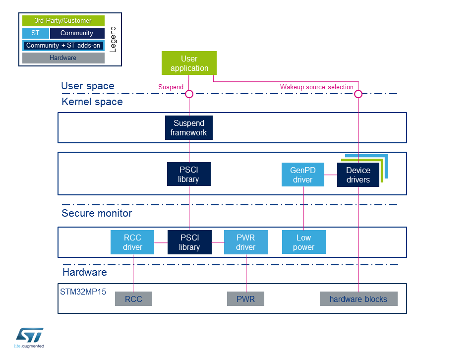
2.1. Component description[edit | edit source]
The OpenSTLinux components for low-power modes are:
Nonsecure world (Linux):
- Power management frameworks: See Power overview for details
- PSCI library: this is a set of standardized functions to request a low-power service to the secure monitor.
- SCMI drivers: driver for system resources (clock, regulators, power domain,...), exposed by OP-TEE with SCMI protocol.
- Device driver: any peripheral driver which needs to control power.
- RCC driver for clock and reset managed by nonsecure world.
- STPMIC1 driver: this driver handles STPMIC1 for STM32MP15 when I2C is not secured (not recommended)
Secure monitor and secure world components (OP-TEE): (see next chapter for details)
- SCMI protocol: see SCMI overview for details.
- PSCI library: generic PSCI stack.
- Low-power driver: the role of this driver is to choose the low-power mode according to the programmed wake-up source(s).
- PM framework: call the low-power callback of each device on the call of Low-power driver.
- OP-TEE drivers: driver of device for system resources (only for A35-TD flavor
 ).
).
- PWR driver: this driver is responsible for configuring the low-power mode.
- RCC driver: this driver handles the circuit secure clocks.
- STPMIC driver: this driver handles STPMIC (STPMIC1 or STPMIC1L present in hardware design), including configuration for the low-power mode
- DDR driver: this driver is responsible to set DDR in self refresh mode
STM32 peripherals (hardware):
2.2. API description[edit | edit source]
The OpenSTLinux power management support is based on Arm® interface specifications:
- Power state coordination interface (PSCI) [1] defines many messages (see identifiers in OP-TEE core/arch/arm/include/sm/psci.h or in Linux include/kvm/arm_psci.h ), for examples:
- CPU_ON/CPU_OFF : used for hotplug feature.
- SYSTEM_OFF : used for power off.
- SYSTEM_RESET : used for system reset.
- SYSTEM_SUSPEND : used to system suspend (deep).
- PSCI_VERSION : return the supported version of the PSCI specication, v1.1 is supported by TF-A.
- System Control and Management Interface (SCMI)[2], see SCMI overview for details.
3. Configuration[edit | edit source]
The objective of this chapter is to explain how to configure OpenSTLinux for low-power modes.
See the page power overview for kernel configuration details.
3.1. Low-power mode in OP-TEE[edit | edit source]
The STPM32MP1 platform low-power is managed in OpenSTLinux with:
- Linux power frameworks, up to PSCI requests
- OP-TEE with code in core/arch/arm/plat-stm32mp1/pm/
- TF-A BL2
The STM32MP1 power management in OP-TEE is configured with:
- OP-TEE configuration switches, for example
- PWR support: CFG_STM32_LOWPOWER_SIP, CFG_STM32_PWR_SIP
- OSI support: CFG_STM32_PSCI_OSI
- OP-TEE device tree, for system and board configuration
- low power mode configuration, see next chapter
- SCMI device tree configuration for exported services
- system resources configuration: STM32MP13 clock tree or STM32MP15 clock tree, regulators provided by PMIC or by external device, security with ETZPC or peripheral features (for example TZEN and MCKPROT for STM32MP15 RCC or secure configuration register
SECCFGRfor securable device).
The low power management (in OP-TEE and also the need of TF-A) is also impacted by the STM32MPU_OP-TEE_profiles (CFG_STM32MP_PROFILE):
- When OP-TEE is running in DDR (CFG_STM32MP1_OPTEE_IN_SYSRAM=n), OP-TEE use TF-A BL2 code to put DDR in self-refresh mode as the last step before it enters sleep mode (for STM32MP13 and for STM32MP15 without pager, so without secure services).
- When OP-TEE is running in SYSRAM (CFG_STM32MP1_OPTEE_IN_SYSRAM=y), OP-TEE embbeded all the needed code for low power sequence (for STM32MP15 with CFG_STM32MP_PROFILE=secure_and_system_services and with pager).
For STMicroelectronic boards the flags are configured with flavors based on the device tree name,
For example: flavorlist-MP1-PWR-OSTL in core/arch/arm/plat-stm32mp1/conf.mk
It is important to synchronize all software components configuration and device trees for the configuration of the used services (SCMI, PSCI, SMC) and for the protection of system resources.
3.2. Supported power modes in OP-TEE[edit | edit source]
This system low-power mode mapping can be modified through PWR node in the secure OS device tree, as described in OP-TEE documentation/devicetree/bindings/regulator/st,stm32mp1-pwr-reg.yaml :
- reduce list of supported modes in system_suspend_supported_soc_modes
- request a STPMIC1 sotfware switch off (STM32_PM_SHUTDOWN to turn off all the STM32MPU supplies) with system_off_soc_mode
By default, the system low power mode for PSCI power off request is "Standby mode with DDR off" to keep supply on the backup domain (STM32_PM_CSTOP_ALLOW_STANDBY_DDR_OFF).
Find below an example in OP-TEE core/arch/arm/dts/stm32mp135f-dk.dts
 &pwr_regulators {
 	system_suspend_supported_soc_modes = <
 		STM32_PM_CSLEEP_RUN
 		STM32_PM_CSTOP_ALLOW_LP_STOP
 		STM32_PM_CSTOP_ALLOW_LPLV_STOP
 		STM32_PM_CSTOP_ALLOW_LPLV_STOP2
 		STM32_PM_CSTOP_ALLOW_STANDBY_DDR_SR
 	>;

 	system_off_soc_mode = <STM32_PM_SHUTDOWN>;
 };
3.3. STPMIC configuration for low-power mode in OP-TEE[edit | edit source]
Refer to PMIC OP-TEE page for details of PMIC configuration in OP-TEE for each power mode, and to application note AN5260 and AN5587 for configuration examples.
In OpenSTLinux, when using a PMIC on a board, it is recommended to use a secure I²C (for example I2C4 or I2C6 on STM32MP15x lines ![]() ) protected by ETPZC and the PMIC is handle only in OP-TEE, exported with SCMI.
) protected by ETPZC and the PMIC is handle only in OP-TEE, exported with SCMI.
It is the default configuration of all STMicroelectronic STM32MP13x lines ![]() boards and only for
boards and only for -ostl configuration of STMicroelectronic STM32MP15x lines ![]() boards.
boards.
It is not the that case for STMicroelectronic STM32MP15x lines ![]() boards device tree present in components because the used I²C is shared with other devices with driver in Linux kernel; in this mode the STPMIC is managed in non secure world but the low power mode of STPMIC is configured by OP-TEE, so the unsecure I²C and STPMIC are shared between secure and secure world and access PWR regulators are exported by SMC to Linux regualtor driver (CFG_STM32_PWR_SIP).
boards device tree present in components because the used I²C is shared with other devices with driver in Linux kernel; in this mode the STPMIC is managed in non secure world but the low power mode of STPMIC is configured by OP-TEE, so the unsecure I²C and STPMIC are shared between secure and secure world and access PWR regulators are exported by SMC to Linux regualtor driver (CFG_STM32_PWR_SIP).
The pm_hint parameter of pmic_regu_pm() is used by the STPMIC (STPMIC1 or STPMIC1L) driver in OP-TEE to configure each regulators according to the selected low-power mode as described in device tree by subnodes.
See OP-TEE device tree in core/arch/arm/dts/stm32mp135f-dk.dts for configuration example:
			vddcpu: buck1 {
				regulator-name = "vddcpu";
				regulator-min-microvolt = <1250000>;
				regulator-max-microvolt = <1350000>;
				regulator-always-on;
				regulator-over-current-protection;

				lp-stop {
					regulator-suspend-microvolt = <1250000>;
				};
				lplv-stop {
					regulator-suspend-microvolt = <900000>;
				};
				lplv-stop2 {
					regulator-off-in-suspend;
				};
				standby-ddr-sr {
					regulator-off-in-suspend;
				};
				standby-ddr-off {
					regulator-off-in-suspend;
				};
			};
| STPMIC1L is only supported in OP-TEE and TF-A with driver for STPMIC2 family (STPMIC1L, STPMIC2L, STPMIC25) OpenSTLinux don't support of STPMIC1L in Linux. So hardware design with STPMIC1L for STM32MP15x lines See example STPMIC manged in OP-TEE with -ostl configuration of STMicroelectronic STM32MP15x lines |
4. How to use the framework[edit | edit source]
4.1. Low-power modes[edit | edit source]
Refer to STM32MP13 reference manuals or STM32MP15 reference manuals for the full description of low-power modes.
The modes are handled by the RCC and the PWR peripherals.
On lower mode requests , Linux stops the whole system activity and a low-power mode is entered with PSCI request. The OP-TEE PSCI stack selects the deepest mode according to the activated wake-up source(s).
STM32MP1 series STMicroelectronic deliveries propose a default mapping of the low-power modes for each type of board and for each PSCI request, this default mapping can be changed thanks to the device tree as explain in a paragraph above
| System mode | Linux Command | PSCI request | DDR state |
|---|---|---|---|
| Stop | freeze (s2idle) |
PSCI_CPU_SUSPEND | SR, VTT on |
| LP-Stop | SR, VTT off | ||
| LPLV-Stop | |||
| Stop | mem (deep) |
PSCI_SYSTEM_SUSPEND | SR, VTT on |
| LP-Stop | SR, VTT off | ||
| LPLV-Stop | |||
| LPLV-Stop2STM32MP13 | |||
| Standby | |||
| Standby | shutdown | PSCI_SYSTEM_OFF | OFF |
| VBAT | |||
| STPMIC1 switch OFF |
With the default configuration used in device tree of STMicroelectronic boards present in each software component of ecosystem release ≤ v6.2.0 ![]() ,
,
PSCI_CPU_SUSPEND for freeze command and s2idle mode is NOT supported.
A new OpenSTLinux configuration named, -ostl, removes this restriction for ecosystem release ≥ v6.2.0 ![]() :
:
With this configuration OP-TEE manages all the system resources (as RCC, PWR and STPMIC) which are exported to Linux with SCMI protocols (clock, reset, regulator, perf for OPP) as it is done on STM32MP2.
This new configuration requires configuration of compilation flags (CFG_STM32_PSCI_OSI=y, CFG_STM32_LOWPOWER_SIP=n, CFG_STM32_PWR_SIP=n) and OP-TE and Linux device trees, with the expected PSCI and SCMI configuration and with STPMIC1 support moved in OP-TEE.
Examples of this configuration are provided for STMicroelectronic boards in External device tree in directory stm32mp1/ with -ostl device tree for each software component:
stm32mp135f-dk-ostlstm32mp157f-dk2-ostlstm32mp157f-ev1-ostl
4.1.1. On STM32MP13x lines  [edit | edit source]
The AN5565 STM32MP13 lines using low-power modes gives more information on these modes and on associated the wake-up sources.
The table below summarizes the device hardware states corresponding to each low-power mode.
| MPU mode | Platform mode | VDDCORE state | VDDCPU state | Clocks state |
|---|---|---|---|---|
| CRun/CSleeep | Run | On | On | On |
| CStop | Stop | On | On | Off |
| LP-Stop | On | On | ||
| LPLV-Stop | Retention | Retention | ||
| CStandby | LPLV-Stop2 | Retention | Off | |
| Standby | Off | Off |
The following tables give the list of wake-up sources available in each mode.
| Platform mode | Available wake-up sources |
|---|---|
| Stop/LP-Stop | Group1 : Group2 + HSE CSS USBH, OTG, ETH |
| LPLV-Stop LPLV-Stop2 |
Group2 : Group3 + PVD, AVD, USART, I2C, SPI, DTS, LPTIM, GPIO |
| Standby | Group3 : BOR, Vbat mon, Temp mon, LSE CSS, RTC, TAMP, Wakeup pins (from PWR) |
4.1.2. On STM32MP15x lines [edit | edit source]
The AN5109 low-power application note also gives more information on these modes, including:
- the detailed description of the operating modes
- the low-power mode entry and exit sequences
- the low-power mode control registers
- the wake-up sources and the software mechanism that ensures the consistency between the low-power mode and the activated wake-up source
The table below summarizes the device hardware states corresponding to each low-power mode.
The term "subsystem" either refers to Arm® Cortex®-A7 (also called MPU) or to Arm® Cortex®-M4 (also called MCU). A mode prefixed by 'C' corresponds to a subsystem mode.
| Level | Mode | VDDCORE state | Subsystem Clocks state |
|---|---|---|---|
| MPU Subsystem | MPU CRun | On | On |
| MPU CStop | On | Off | |
| MPU CStandby | On | Off + MPU reset on wakeup | |
| MCU Subsystem | MCU CRun | On | On |
| MCU CStop | On | Off |
A platform mode is the combination of MPU and MCU modes, only the some MPU mode are used in OpenSTLinux for each platform mode
| MPU mode | MCU mode | Platform mode | VDDCORE state | Clocks state |
|---|---|---|---|---|
| CRun/CSleep CStop/CStandby |
CRun | Run | On | On |
| CStop/CStandby | CStop | Stop (LPDS = 0) |
Retention | Off |
| CStop/CStandby | CStop | LP-Stop (LPDS = 1) |
Retention Low-power mode |
Off |
| CStop/CStandby | CStop | LPLV-Stop (LPDS and LVDS = 1) |
Retention Low-power Low-voltage mode |
Off |
| CStandby | CStop MCU PDDS = 1 |
Standby | Off | Off |
See config_power[] in core/arch/arm/plat-stm32mp1/pm/low_power.c for mapping in OP-TEE.
The following tables give the list of wake-up sources available in each mode.
| Plaform mode | Available wake-up sources |
|---|---|
| Stop LP-Stop |
Group1 : Group2 + USB, CEC, ETH, USART, I²C, SPI, LPTIM |
| LPLV-Stop | Group2 : Group3 + PVD, AVD, GPIO |
| Standby | Group3: BOR, Vbat mon, Temp mon, LSE CSS, RTC, TAMP, Wakeup pins (from PWR) |
This list of Wake-up capability peripheral for each mode is defined in the Table 35. Functionalities depending on system operating mode of the STM32MP15 reference manuals.
4.2. PSCI topology[edit | edit source]
The PSCI specification defines the concept of the power domain topology tree and in OpenSTLinux, each STM32MP1 series low power mode is associated to a PSCI State-id, which uses the ARM Recommended StateID Encoding with OS initiated support.
For PSCI suspend requests, STM32MP1 series supports 4 power levels in the PSCI topology to handle PSCU_CPU_SUSPEND request define in core/arch/arm/plat-stm32mp1/pm/psci.c with values aligned on STM32MP2 PSCI topology.
#define STM32_STATE_ID_CPU_PWRDN        U(0x1)
#define STM32_STATE_ID_STOP1            U(0x11)
#define STM32_STATE_ID_LP_STOP1         U(0x21)
#define STM32_STATE_ID_LPLV_STOP1       U(0x211)
4.3. PSCI_CPU_SUSPEND support[edit | edit source]
PSCI_CPU_SUSPEND is supported when CFG_STM32_PSCI_OSI is activated in OP-TEE and when the PSCI power domains are defined in Linux device tree, see -ostl device trees for examples on STMicroelectronic board.
Linux kernel sent the PSCI_CPU_SUSPEND to OP-TEE after a S2IDLE/FREEZE system request and for PSCI CPUIdle OS initiated mode (PSCI OSI). They are described in the SoC device tree using the hierarchical model with nodes idle-states and domain-idle-states as described in Documentation/devicetree/bindings/arm/psci.yaml (see Power overview for detail).
The targeted arm,psci-suspend-param, based on this topology, is provided to PCSI stack in PSCI_CPU_SUSPEND requested (see Power overview).
4.4. PSCI_SYSTEM_SUSPEND support[edit | edit source]
Linux kernel sent the PSCI_SYSTEM_SUSPEND to OP-TEE after "DEEP"/"S2RAM" request (see Power overview for details). The activated wake-up are checked in OP-TEE to select the lowest supported mode in core/arch/arm/plat-stm32mp1/pm/power_config.c according the OpenSTLinux configuration and based:
- either on proprietary SMC (CFG_STM32_LOWPOWER_SIP) used by Linux STM32 power domain driver
- either on value of EXTI IMR register, i.e. the PSCI platform-coordinated mode, for new
-ostlconfiguration
If a low-power mode is not supported by a board design, it must be removed in OP-TEE device tree.
4.5. PSCI stack in OP-TEE[edit | edit source]
The OP-TEE PSCI stack calls the STM32MP1 platform hooks (see ccore/arch/arm/plat-stm32mp1/pm/psci.c )
For PSCI_SYSTEM_SYSTEM request the targeted low power mode is selected in core/arch/arm/plat-stm32mp1/pm/power_config.c according the OpenSTLinux configuration (CFG_STM32_LOWPOWER_SIP).
In OP-TEE PM framework, the targeted power level is indicated with pm_hint parameter of API pm_change_state() (called in core/arch/arm/plat-stm32mp1/pm/context.c ) and transmit to each OP-TEE drivers to save/restore the device configuration (see core/include/kernel/pm.h and core/arch/arm/plat-stm32mp1/stm32mp_pm.h for details).
When it is done, the last sequence of entry in low power mode, the DDR is set in self-refresh mode and the DDR (means no more accessible), so this part must be executed in SYSRAM:
- When OP-TEE is running in SYSRAM, OP-TEE embedded all the needed code for low power sequence:
- low power code in: core/arch/arm/plat-stm32mp1/pm/low_power.c
- DDR driver: core/arch/arm/plat-stm32mp1/drivers/stm32mp1_ddrc.c
- When OP-TEE is running in DDR, OP-TEE use a low power code resident in SYSRAM and installed by TF-A BL2:
- OP-TEE function
stm32mp_pm_call_bl2_lp_entry() - TFA code: plat/st/stm32mp1/stm32mp1_critic_power.c
- OP-TEE function
A shared context in BKPSRAM (see details in STM32MP13 and STM32MP15 RAM mapping) is used to transmit the information between TF-A BL2 and OP-TEE.
This context is used for standby mode exit and, if needed, by the TF-A BL2 resident code in SYSRAM; it is defined by:
- in OP-TEE: core/arch/arm/plat-stm32mp1/pm/context.h
- in TF-A: plat/st/stm32mp1/stm32mp1_context.c
This context save values needed to restore the system when system exit of low power, including DDR access.
As the FIP with the OP-TEE firmware can be updated independently from TF-A BL2, the context format must be backward compatible and the context CRC and version is checked before any access to its content.
5. Source code location[edit | edit source]
Below are listed the software frameworks and drivers managing the OpenSTLinux power management.
- Linux®: Linux power management with STM32 drivers
- STM32 power domains driver with SMC: drivers/soc/st/stm32_pm_domain.c
- STM32 generic power domains driver for OSI: drivers/pmdomain/st/stm32mp-pm-domain.c
- STM32 MP15 cpu freq driver: drivers/cpufreq/stm32-cpufreq.c
- OP-TEE:
- PSCI and power management implementation: core/arch/arm/plat-stm32mp1/pm/
- PM framework: core/kernel/pm.c and core/include/kernel/pm.h
- For each device driver, the PM function registered by register_pm_core_service_cb()
- TF-A:
- Low-power entry, exit, DDR self refresh handling: plat/st/stm32mp1/stm32mp1_critic_power.c
- And drivers for each internal peripheral or external component are described in the associated pages:
6. How to trace and debug[edit | edit source]
See How to debug TF-A BL2 and How_to_debug_OP-TEE to activate the traces.
7. To go further[edit | edit source]
Refer to reference manual for a detailed description of low-power modes and peripheral wake-up sources:
The following application notes gives additional information on the hardware settings used for low-power management:
- AN5109 - Guidelines for using low-power modes
- AN5260 - STM32MP151/153/157 MPU lines and STPMIC1B integration on a battery powered application
- AN5284 - STM32MP1 series system power consumption
- AN5565 - STM32MP13 lines using low-power modes
- AN5587 - STM32MP13x MPU product lines and STPMIC1D / STPMIC1A integration on a wall adapter supply
- AN5787 - STM32MP13x product lines system power consumption
8. References[edit | edit source]
- ↑ Arm Power State Coordination Interface (PSCI):
https://developer.arm.com/documentation/den0022 - ↑ Arm System Control and Management Interface Platform Design Document (SCMI) specification:
https://developer.arm.com/documentation/den0056
Arm® is a registered trademark of Arm Limited (or its subsidiaries) in the US and/or elsewhere. ![]()
Arm® is a registered trademark of Arm Limited (or its subsidiaries) in the US and/or elsewhere. ![]()