1. Article purpose[edit | edit source]
The purpose of this article is to explain how to configure the LPTIM internal peripheral using the device tree mechanism, relying on the bindings documentation, that is the description of the required and optional device-tree properties.
When the peripheral is assigned to Linux® OS, it explains:
- how to enable PWM, trigger, event counter and quadrature encoder
- how to configure the board, e.g. LPTIM input/output pins
It can be used by the LPTIM OpenSTLinux drivers that registers relevant information in PWM, IIO and counter frameworks, or by the OP-TEE LPTIM counter driver .
The peripheral can be assigned to different contexts/software components, depending on the final product needs. Refer to How to assign an internal peripheral to an execution context for guidelines on this configuration.
2. DT bindings documentation[edit | edit source]
The device tree binding documents are stored in the Linux kernel repository for:
- OP-TEE and Linux® OS : Documentation/devicetree/bindings/mfd/st,stm32-lptimer.yaml
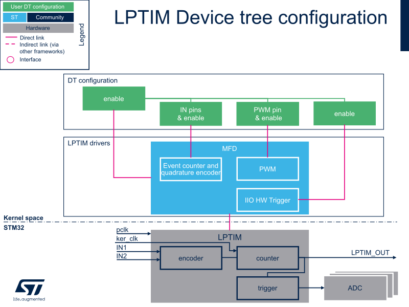
The LPTIM[1] is a multifunction device (MFD), providing the following functions:
- st,stm32-timers deals with core resources (e.g. registers, clock)
- st,stm32-pwm deals with PWM interface resources (e.g. PWM pins)
- st,stm32-timer-trigger deals with LPTIM triggers resources (e.g. trigger output connected to other STM32 internal peripherals)
- st,stm32-timer-counter deals with LPTIM counter and quadrature encoder resources (e.g. counter/encoder IN[1..2] pins)
- "st,stm32-timer-timer" deals with "clock events"[2] for the kernel.
3. DT configuration[edit | edit source]
This hardware description is a combination of the STM32 microprocessor device tree files (.dtsi extension) and board device tree files (.dts extension). See the Device tree for an explanation of the device-tree file organization.
STM32CubeMX can be used to generate the board device tree. Refer to How to configure the DT using STM32CubeMX for more details.
3.1. DT configuration (STM32 level)[edit | edit source]
DT root node (aka lptimer1, ..., lptimer5) and DT child nodes describe the LPTIM features such as:
- PWM.
- trigger.
- event counter and quadrature encoder.
- timer (clockevent).
They also describe hardware parameters such as register addresses and clock.
The LPTIM device is declared as follows:
- for STM32MP13x lines
 , the LPTIM nodes are declared in stm32mp131.dtsi[3].
- for STM32MP15x lines , the LPTIM nodes are declared in stm32mp151.dtsi[4].
 lptimer1: timer@40009000 {
 	compatible = "st,stm32-lptimer";                  /* lptimer's common resources */
 	...
 	pwm {
 		compatible = "st,stm32-pwm-lp";               /* PWM part of LPTIM */
 	};
 	trigger@0 {
 		compatible = "st,stm32-lptimer-trigger";      /* trigger part of LPTIM */
 		reg = <0>;                                    /* trigger identifier (e.g. 0 for LPTIM1 trigger, 1 for LPTIM2... */
 	};
 	counter {
 		compatible = "st,stm32-lptimer-counter";      /* quadrature encoder & event counter part of LPTIM */
 	};
 	timer {
 		compatible = "st,stm32-lptimer-timer";        /* clkevent part of LPTIM */
 		status = "disabled";
 	};
 };
On ecosystem release ≥ v6.1.0 ![]() , the LPTIM device is declared as follows:
, the LPTIM device is declared as follows:
- for STM32MP21x lines , the LPTIM nodes are declared in stm32mp211.dtsi[5].
 lptimer1: timer@40200000 {
 	/* lptimer's common resources */
 	compatible = "st,stm32mp21-lptimer", "st,stm32-lptimer";
 	...
 	counter {        /* quadrature encoder & event counter part of LPTIM               */
 		compatible = "st,stm32mp21-lptimer-counter", "st,stm32-lptimer-counter";
 	};
 	pwm {            /* PWM part of LPTIM                                              */
 		compatible = "st,stm32mp21-pwm-lp", "st,stm32-pwm-lp";
 	};
 	timer {          /* clkevent part of LPTIM                                         */
 		compatible = "st,stm32mp21-lptimer-timer", "st,stm32-lptimer-timer";
 	};
 	trigger@0 {      /* trigger part of LPTIM                                          */
 		compatible = "st,stm32mp21-lptimer-trigger", "st,stm32-lptimer-trigger";
 		reg = <0>;   /* trigger identifier (e.g. 0 for LPTIM1 trigger, 1 for LPTIM2... */
 	};
 };
- for STM32MP23x lines , the LPTIM nodes are declared in stm32mp231.dtsi[6].
- for STM32MP25x lines , the LPTIM nodes are declared in stm32mp251.dtsi[7].
 lptimer1: timer@40090000 {
 	/* lptimer's common resources */
 	compatible = "st,stm32mp25-lptimer", "st,stm32-lptimer";
 	...
 	counter {        /* quadrature encoder & event counter part of LPTIM               */
 		compatible = "st,stm32mp25-lptimer-counter", "st,stm32-lptimer-counter";
 	};
 	pwm {            /* PWM part of LPTIM                                              */
 		compatible = "st,stm32mp25-pwm-lp", "st,stm32-pwm-lp";
 	};
 	timer {          /* clkevent part of LPTIM                                         */
 		compatible = "st,stm32mp25-lptimer-timer", "st,stm32-lptimer-timer";
 	};
 	trigger@0 {      /* trigger part of LPTIM                                          */
 		compatible = "st,stm32mp25-lptimer-trigger", "st,stm32-lptimer-trigger";
 		reg = <0>;   /* trigger identifier (e.g. 0 for LPTIM1 trigger, 1 for LPTIM2... */
 	};
 };
Same compatible is used on both STM32MP23x lines ![]() and STM32MP25x lines
and STM32MP25x lines ![]() .
.
For ecosystem release v6.0.0 ![]() , the LPTIM device is declared as follows:
, the LPTIM device is declared as follows:
- for STM32MP21x lines , the LPTIM nodes are declared in stm32mp211.dtsi[5].
 lptimer1: timer@40200000 {
 	/* lptimer's common resources */
 	compatible = "st,stm32mp21-lptimer";
 	...
 	counter {        /* quadrature encoder & event counter part of LPTIM */
 		compatible = "st,stm32mp21-lptimer-counter";
 	};
 	pwm {            /* PWM part of LPTIM                                */
 		compatible = "st,stm32mp21-pwm-lp";
 	};
 	timer {          /* clkevent part of LPTIM                           */
 		compatible = "st,stm32mp21-lptimer-timer";
 	};
 	trigger@0 {      /* trigger part of LPTIM                            */
 		compatible = "st,stm32mp21-lptimer-trigger";
 		reg = <0>;   /* trigger identifier (e.g. 0 for LPTIM1 trigger, 1 for LPTIM2... */
 	};
 };
- for STM32MP23x lines , the LPTIM nodes are declared in stm32mp231.dtsi[6].
- for STM32MP25x lines , the LPTIM nodes are declared in stm32mp251.dtsi[7].
 lptimer1: timer@40200000 {
 	/* lptimer's common resources */
 	compatible = "st,stm32mp25-lptimer";
 	...
 	counter {        /* quadrature encoder & event counter part of LPTIM */
 		compatible = "st,stm32mp25-lptimer-counter";
 	};
 	pwm {            /* PWM part of LPTIM                                */
 		compatible = "st,stm32mp25-pwm-lp";
 	};
 	timer {          /* clkevent part of LPTIM                           */
 		compatible = "st,stm32mp25-lptimer-timer";
 	};
 	trigger@0 {      /* trigger part of LPTIM                            */
 		compatible = "st,stm32mp25-lptimer-trigger";
 		reg = <0>;   /* trigger identifier (e.g. 0 for LPTIM1 trigger, 1 for LPTIM2... */
 	};
 };
Same compatible is used on both STM32MP23x lines ![]() and STM32MP25x lines
and STM32MP25x lines ![]() .
.
3.2. DT configuration (board level)[edit | edit source]
The objective of this chapter is to explain how to enable and configure the LPTIM DT nodes for a board:
- Enable DT root node for the LPTIM instance in use (e.g lptimer1, ..., lptimer5), with status = "okay";
- Enable DT child node(s) for the feature(s) in use (PWM output, trigger, event counter and quadrature encoder), with status = "okay";
- Configure the pins in use via pinctrl, with pinctrl-0, pinctrl-1 and pinctrl-names.
Peripheral configuration should be done in specific board device tree files (board dts file and pinctrl dtsi file).
3.3. DT configuration examples[edit | edit source]
3.3.1. LPTIM1 configured as PWM and trigger source[edit | edit source]
The example below shows how to configure LPTIM1 to act as:
- PWM output on PG13 (See pinctrl device tree configuration and GPIO internal peripheral)
- trigger source (in Synchronous mode with PWM) for other internal peripherals such as ADC[8], DAC[9], and DFSDM[10]
lppwm1_pins_a: lppwm1-0 {
 	pins {
		pinmux = <STM32_PINMUX('G', 13, AF1)>;    /* configure 'PG13' as alternate 1 for LPTIM1_OUT mode of operation */
		bias-pull-down;
		drive-push-pull;
		slew-rate = <0>;
 	};
};
lppwm1_sleep_pins_a: lppwm1-sleep-0 {
	pins {
		pinmux = <STM32_PINMUX('G', 13, ANALOG)>; /* configure 'PG13' as analog for low power mode */
	};
};
&lptimer1 {
	status = "okay";
	pwm {
		pinctrl-0 = <&lppwm1_pins_a>;             /* configure PWM on LPTIM1_OUT */
		pinctrl-1 = <&lppwm1_sleep_pins_a>;
		pinctrl-names = "default", "sleep";
		status = "okay";                          /* enable PWM on LPTIM1 */
	};
	trigger@0 {
		status = "okay";                          /* enable LPTIM1_OUT trigger source */
	};
};
3.3.2. LPTIM2 configured as counter and quadrature encoder[edit | edit source]
The example below shows how to configure LPTIM2 to act as counter and/or quadrature encoder, with LPTIM2_IN1 and LPTIM2_IN2 pins configured as inputs on PD12 and PD11, respectively (See pinctrl device tree configuration and GPIO internal peripheral)
# part of pin-controller dt node
lptim2_in_pins_a: lptim2-in-pins-0 {
	pins {
		pinmux = <STM32_PINMUX('D', 12, AF3)>, /* LPTIM2_IN1 */
			 <STM32_PINMUX('D', 11, AF3)>; /* LPTIM2_IN2 */
		bias-disabled;
	};
};
lptim2_sleep_in_pins_a: lptim2-sleep-in-pins-0 {
	pins {
		pinmux = <STM32_PINMUX('D', 12, ANALOG)>, /* LPTIM2_IN1 */
			 <STM32_PINMUX('D', 11, ANALOG)>; /* LPTIM2_IN2 */
	};
};
&lptimer2 {
	status = "okay";
	counter {
		pinctrl-0 = <&lptim2_in_pins_a>;          /* configure LPTIM2 counter/encoder pins */
		pinctrl-1 = <&lptim2_sleep_in_pins_a>;
		pinctrl-names = "default", "sleep";
		status = "okay";                          /* enable counter/encoder on LPTIM2 */
	};
};
3.3.3. LPTIM3 configured as hrtimer[edit | edit source]
The example below shows how to configure LPTIM3 to act as a high-resolution timer in the Linux® kernel.
It's used to schedule events in low power modes, see timer documentation for details.
On STM32MP2 series, LPTIM3 has been activated by default in the board device tree files with:
/* use LPTIMER with tick broadcast for suspend mode */
&lptimer3 {
	status = "okay";
	timer {
		status = "okay";
	};
};
4. How to configure the DT using STM32CubeMX[edit | edit source]
The STM32CubeMX tool can be used to configure the STM32MPU device and get the corresponding platform configuration device tree files.
STM32CubeMX may not support all the properties described in DT binding files listed in the above DT bindings documentation paragraph. If so, the tool inserts user sections in the generated device tree. These sections can then be edited to add some properties, and they are preserved from one generation to another. Refer to STM32CubeMX user manual for further information.
5. References[edit | edit source]
Refer to the following links for additional information:
- ↑ LPTIM internal peripheral
- ↑ Documentation/timers/timekeeping.rst
- ↑ STM32MP131 device tree file
- ↑ STM32MP151 device tree file
- ↑ 5.0 5.1 STM32MP211 device tree file
- ↑ 6.0 6.1 STM32MP231 device tree file
- ↑ 7.0 7.1 STM32MP251 device tree file
- ↑ ADC internal peripheral
- ↑ DAC internal peripheral
- ↑ DFSDM internal peripheral