The purpose of this article is to describe the basic steps required to tune or troubleshoot the USB High-Speed PHYs from hardware and software perspectives.
1. Eye diagram tuning for USBPHYC[edit | edit source]
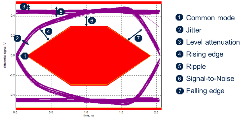
The USBPHYC block is applicable to STM32MP1 series. It provides analog tuning controls that can be used to improve the USB High-Speed eye diagram depending on the board layout, routing quality, and signal integrity. Typical adjustments concern the HS driver current, slew rate, rise/fall time behavior, squelch threshold, and impedance matching. These parameters are exposed through the USBPHYC device tree binding and should generally be left at their default values unless board validation or compliance testing shows the need for fine tuning.
1.1. General recommendations[edit | edit source]
The eye diagram is characterized using a specific reference resistor which it to be fitted to the board. This resistor is to placed between the STM32 MPU USB_RREF pin and the ground plane.
First ensure that USB_RREF resistor is correctly connected and has the specified value and accuracy, which is of 3 kΩ +/- 1%).
1.2. Common mode troubleshooting[edit | edit source]
- Hardware root causes to investigate
- Mismatch between D+ and D- (in terms of length and/or parallelism)
- Check the layout and add a common mode filter (e.g. ECMF02-2AMX6[1])
 Information Information
|
| It is not possible to solve common mode issue with a software solution. |
1.3. Jitter troubleshooting[edit | edit source]
- Hardware root causes to investigate
- Excessive capacitance on D+/D- lines from the components or the PCB.
- USB power/GND instability
- Check decoupling and the grounding
- Fine tuning may be performed by using the USBPHYC device tree configuration [2]
High jitter has a HW root cause in most cases.
- USBPHYC_TUNEx.HSDRVRFRED
- 0 : increases the rising edge but adds jitter (i.e. remove st,enable-hs-rftime-reduction;[3])
- USBPHYC_TUNEx.INCURREN/.INCURRINT
- Tune current increase with .INCURREN or .INCURRINT (i.e. remove st,current-boost-microamp= <n>;[3] or set it to 1000µA or 2000µA)
- USBPHYC_TUNEx.HSDRVCHKITRM
- Reduce the increase of the main level (i.e. reduce value of st,trim-hs-current = <n>;[3])
1.4. Level attenuation or Signal-to-Noise troubleshooting[edit | edit source]
- Hardware root causes to investigate
- Excessive serial resistance and capacitance on D+/D- lines from the components or the PCB.
- USB power/GND instability
- Check decoupling / Check grounding
- Software potential tuning
- USBPHYC_TUNEx.HSDRVCHKITRM
- Higher the value, higher is the level of the signal (i.e. increase the value of st,trim-hs-current = <n>;[3]).
- As a consequence noise and ripples can appear.
- USBPHYC_TUNEx.HSDRVCURINCR/.HSDRVDCLEV
- Higher the value, higher is the margin for the level (i.e. increase value of st,tune-hs-dc-level = <n>;[3]).
- But jitter on the rising edge, and noise can appear
1.5. Rising edge or Falling edge troubleshooting[edit | edit source]
- Hardware root causes to investigate
- Excessive serial resistance and capacitance on D+/D- lines from the components or the PCB.
- Impedance mismatch : check characteristic impedance of lines, stubs and so on…
- Possible software tuning
- USBPHYC_TUNEx.HSDRVRFRED
- 0: improve rising edge. This is done by removing st,enable-hs-rftime-reduction;[3].
- 1: slow-down rising edge. This is done by adding st,enable-hs-rftime-reduction;.
- This has a potential impact on jitter
- USBPHYC_TUNEx.HSDRVCHKITRM
- Depending on the level, the slope is increased/decreased. This is done by adjusting the value of st,trim-hs-current = <n>;[3]
- USBPHYC_TUNEx.HSDRVSLEW
- 0: normal rising edge. This is done by removing st,decrease-hs-slew-rate;[3]
- 1: reduce rising edge. This is done by adding st,decrease-hs-slew-rate;
- This is useful to reduce a hill shape ripple on top of rising/falling edge
- USBPHYC_TUNEx.HSDRVCURINCR/.HSDRVDCLEV
- Improve slope speed. This is done by increasing the value of st,tune-hs-dc-level = <n>;[3].
- The inconvenience is that jitter on the rising edge, and noise can appear
1.6. Ripple troubleshooting[edit | edit source]
- Hardware root causes to investigate
- Impedance mismatch : check the characteristic impedance of all the lines, stubs and so on…
- Software potential tuning
- USBPHYC_TUNEx.HSDRVCHKZTRM[1:0]
- 00: Usually opens the eye but can create some jitter and ripple. This is achieved by setting st,trim-hs-impedance = <0>;[3].
- 11: Close the eye but can reduce jitter and ripple. This is achieved by setting st,trim-hs-impedance = <3>;.
- USBPHYC_TUNEx.HSDRVSLEW
- 0: normal rising edge. This is done by removing st,decrease-hs-slew-rate;[3]
- 1: reduce rising edge. This is done by adding st,decrease-hs-slew-rate;
- Useful to reduce a hill shape ripple on top of rising/falling edge
2. Eye diagram tuning for USB2PHY[edit | edit source]
The USB2PHY block is applicable to STM32MP2 series. These SoCs contain two USB2PHY instances:
- For STM32MP21x lines
 , one instance is used for the USBH controller and the other one is used for the USB OTG controller.
 - For STM32MP23x lines and STM32MP25x lines , one instance is used for the USBH controller and the other one is used for the USB3DR controller.
The USB2PHY block exposes tuning controls through the SYSCFG registers and can be used to improve the USB High-Speed eye diagram and signal integrity. The corresponding device tree properties map to tuning fields in SYSCFG_USB2PHY1TRIM1CR/SYSCFG_USB2PHY2TRIM1CR, and SYSCFG_USB2PHY1TRIM2CR/SYSCFG_USB2PHY2TRIM2CR.
| Information
|
| As for USBPHYC, these values should typically remain at their default settings unless validation on the target board requires tuning. |
2.1. General recommendations[edit | edit source]
On STM32MP2 series, USB2PHY analog biasing and reference settings are managed internally by the USB2PHY block via its SYSCFG tuning registers, rather than through an external USB_RREF pin as on STM32MP1 series.
Detailed guidance on USB2PHY tuning is not yet available. In the meantime, this article on eye diagram analysis for signal integrity is a good resource for understanding what to look for: https://www.protoexpress.com/blog/analyzing-eye-diagrams-for-signal-integrity-high-speed-pcbs/.
3. Link between register values and the device tree description[edit | edit source]
3.1. USBPHYC[edit | edit source]
Only few bitfields need to be adjusted in the scope of Eye Diagram tuning. It is recommended to keep all other as described in default device tree examples. See also USBPHYC device tree bindings[3]
| Device Tree item | details | USBPHYC_TUNEx field |
|---|---|---|
| st,current-boost-microamp | <1000> current boosting of 1mA | .INCURREN=1/.INCURRINT=0 |
| <2000> current boosting of 2mA | .INCURREN=1/.INCURRINT=1 | |
| st,no-lsfs-fb-cap | Disables the LS/FS feedback capacitor | .LFSCAPEN=0 |
| st,decrease-hs-slew-rate | Slows the HS driver slew rate by 10% | .HSDRVSLEW=1 |
| st,tune-hs-dc-level | <0> normal level | .HSDRVCURINCR=0/.HSDRVDCCUR=0 |
| <1> increases the HS driver DC level by 5 to 7mV | .HSDRVCURINCR=1/.HSDRVDCLEV=0 | |
| <2> increases the HS driver DC level by 10 to 14mV | .HSDRVCURINCR=1/.HSDRVDCLEV=1 | |
| <3> decreases the HS driver DC level by 5 to 7mV | .HSDRVDCCUR=1 | |
| st,enable-fs-rftime-tuning | Enables the FS rise/fall tuning option | .FSDRVRFADJ=1 |
| st,enable-hs-rftime-reduction | Enables the HS rise/fall reduction feature | .HSDRVRFRED=1 |
| st,trim-hs-current | Controls HS driver current trimming for choke | .HSDRVCHKITRM=n [0:15] |
| st,trim-hs-impedance | Controls HS driver impedance tuning for choke | .HSDRVCHKZTRM=n [0:3] |
| st,tune-squelch-level | Adjusts the squelch DC threshold value | .SQLCHCTL=n [0:3] |
| st,enable-hs-rx-gain-eq | Enables the HS Rx gain equalizer | .HDRXGNEQEN=1 |
| st,tune-hs-rx-offset | Adjusts the HS Rx offset | .HSRXOFF=n [0:3] |
| st,no-hs-ftime-ctrl | Disables the HS fall time control of single ended signals during pre-emphasis | .HSFALLPREEM=1 |
| st,no-lsfs-sc | Disables the short circuit protection in LS/FS driver | .SHTCCTCTLPROT=0 |
| st,enable-hs-tx-staggering | Enables the basic staggering in HS Tx mode | .STAGSEL=1 |
3.2. USB2PHY[edit | edit source]
Only few bitfields need to be adjusted in the scope of Eye Diagram tuning. It is recommended to keep all other as described in default device tree examples. See also USB2PHY device tree bindings[4].
| Device Tree item | details | SYSCFG USB2PHY2 field |
|---|---|---|
| st,pll-ipath-tune | PLL Integral Path Tune | USB2PHY2PLLITUNE[1:0] (SYSCFG_USB2PHY2TRIM2CR) |
| st,pll-ppath-tune | PLL Proportional Path Tune | USB2PHY2PLLPTUNE[3:0] (SYSCFG_USB2PHY2TRIM2CR) |
| st,comp-dis-tune | Disconnect Threshold Adjustment | USB2PHY2COMPDISTUNE[2:0] (SYSCFG_USB2PHY2TRIM1CR) |
| st,sqrx-tune | Squelch Threshold Adjustment | USB2PHY2SQRXTUNE[2:0] (SYSCFG_USB2PHY2TRIM1CR) |
| st,vdatref-tune | Data Detect Voltage Adjustment | USB2PHY2VDATREFTUNE[1:0] (SYSCFG_USB2PHY2TRIM1CR) |
| st,otg-tune | VBUS Valid Threshold Adjustment | USB2PHY2OTGTUNE[2:0] (SYSCFG_USB2PHY2TRIM1CR) |
| st,txhsxv-tune | Transmitter High-Speed Crossover Adjustment | USB2PHY2TXHSXVTUNE[1:0] (SYSCFG_USB2PHY2TRIM1CR) |
| st,txfsls-tune | FS/LS Source Impedance Adjustment | USB2PHY2TXFSLSTUNE[3:0] (SYSCFG_USB2PHY2TRIM1CR) |
| st,txvref-tune | HS DC Voltage Level Adjustment | USB2PHY2TXVREFTUNE[3:0] (SYSCFG_USB2PHY2TRIM1CR) |
| st,txrise-tune | HS Transmitter Rise/Fall Time Adjustment | USB2PHY2TXRISETUNE[1:0] (SYSCFG_USB2PHY2TRIM1CR) |
| st,txres-tune | USB Source Impedance Adjustment | USB2PHY2TXRESTUNE[1:0] (SYSCFG_USB2PHY2TRIM1CR) |
| st,txpreempamp-tune | HS Transmitter Pre-emphasis Current Control | USB2PHY2TXPREEMPAMPTUNE[1:0] (SYSCFG_USBHCR) |
| st,txpreemppulse-tune | HS Transmitter Pre-emphasis Duration Control | USB2PHY2TXPREEMPPULSETUNE (SYSCFG_USBHCR) |
4. Software configuration[edit | edit source]
This section describes how to configure the software to enter test modes. It also provides configuration tips that can be used for USB compliance testing.
4.1. Linux kernel configuration[edit | edit source]
USB support (CONFIG_USB=y) is located in the kernel configuration with the Linux Menuconfig tool: Menuconfig or how to configure kernel.
- Electrical test fixtures (PIDVID)
To enable the electrical test fixtures[5] used for the USB-IF Embedded Host High-Speed Electrical Test procedure, select CONFIG_USB_EHSET_TEST_FIXTURE:
Device Drivers  --->
   --- USB support
   <*>   USB EHSET Test Fixture driver
- Embedded high-speed host electrical test with the "Single Step Set Feature"
The PIDVID test fixture enumerates with "VID:0x1A0A, PID:0x0108" in this test[6]. To enable support for this test, select CONFIG_USB_HCD_TEST_MODE:
Device Drivers  --->
   --- USB support
   [*]   HCD test mode support
- Disable external HUB
This allows the reduction of hardware and software costs by not supporting external hubs for USB compliance test. This may be appropriate during Embedded Host (EH) compliance testing. To disable external HUB support, select CONFIG_USB_OTG_DISABLE_EXTERNAL_HUB:
Device Drivers  --->
   --- USB support
   [*]   Disable external hubs
- Limit the number of enumeration retries
Linux kernel tries, by default, to enumerate all failing devices. The USB OTG specification requires a host to detect a failed initialization within 30 seconds. This is needed for "A-UUT 'Device No Response' for connection timeout". To limit the number of retries, select CONFIG_USB_FEW_INIT_RETRIES:
Device Drivers  --->
   --- USB support
   [*]   Limit USB device initialization to only a few retries
- Target Peripheral List
The Target Peripheral List (TPL) is used to identify targeted devices during Embedded Host (EH) compliance testing (refer to the USB OTG and EH specification). To enable TPL support, select CONFIG_USB_OTG_PRODUCTLIST:
Device Drivers  --->
   --- USB support
   [*]   Rely on OTG and EH Targeted Peripherals List
The otg_productlist.h[7] file will then be used as a product list.
4.2. Device tree configuration[edit | edit source]
The TPL is used to identify targeted devices during HE compliance testing. The user can add tpl-support property for each controller, in the board device tree file, to enable it.
# Enable Target Peripheral List on USBH, on both EHCI and OHCI controllers:
&usbh_ehci {
+	tpl-support;
};

&usbh_ohci {
+	tpl-support;
};
On STM32MP1 series and STM32MP21x lines
# Enable Target Peripheral List on OTG:
&usbotg_hs {
+	tpl-support;
};
On STM32MP23x lines and STM32MP25x lines
&usb3dr {
	dwc3: usb@48300000 {
+		tpl-support;
	};
};
5. References[edit | edit source]
- ↑ ECMF02-2AMX6
- ↑ USBPHYC device tree configuration
- ↑ 3.00 3.01 3.02 3.03 3.04 3.05 3.06 3.07 3.08 3.09 3.10 3.11 Documentation/devicetree/bindings/phy/phy-stm32-usbphyc.yaml , USBPHYC device tree bindings
- ↑ Documentation/devicetree/bindings/phy/st,stm32-usb2phy.yaml , USB2PHY device tree bindings
- ↑ USB-IF USB2 test fixtures
- ↑ Embedded Host High Speed Electrical Test Procedure
- ↑ drivers/usb/core/otg_productlist.h , otg_productlist.h