This article lists all internal peripherals embedded in STM32MP13x lines ![]() and shows the assignment possibilities to the execution contexts for each one of them.
and shows the assignment possibilities to the execution contexts for each one of them.
From this article, you can also access to individual peripheral articles with information related to the overview and configuration aspects.
1. Internal peripherals overview[edit | edit source]
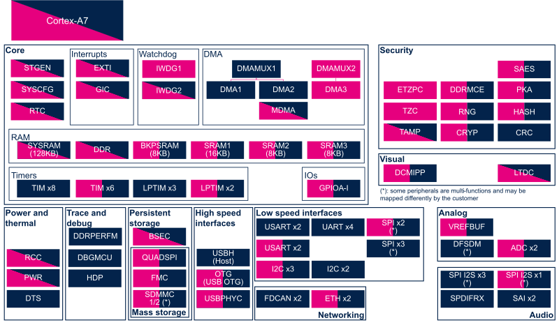
The figure below shows all peripherals embedded in STM32MP13x lines ![]() , grouped per functional domains that are reused in many places of this wiki to structure the articles.
, grouped per functional domains that are reused in many places of this wiki to structure the articles.
Several execution contexts exist on STM32MP13x lines ![]() [1], corresponding to the Arm Cortex-A7 security modes:
[1], corresponding to the Arm Cortex-A7 security modes:
- Arm Cortex-A7 secure (Trustzone), running ROM code and TF-A BL2 at boot time, and running OP-TEE at runtime
- Arm Cortex-A7 non secure , running U-Boot at boot time, and running Linux at runtime
Some peripherals can be strictly assigned to one execution context, this is the case for most of the peripherals, like USART or I2C.
Other ones can be shared between several execution contexts, this is the case for system peripherals like PWR or RCC.
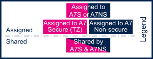
The legend below shows how assigned and shared peripherals are identified in the assignment diagram that follows.
Both the diagram below and the following summary table (in Internal peripherals runtime assignment and Internal peripherals boot time assignment chapters below) are clickable in order to jump to each peripheral overview article and get more detailed information (like the software frameworks used to control them). They list STMicroelectronics recommendations. The STM32MP13 reference manual [2] may expose more possibilities then what is shown here.

2. Internal peripherals runtime assignment[edit | edit source]
Click on ![]() to expand or collapse the legend...
to expand or collapse the legend...
Check boxes illustrate the possible peripheral allocations supported by the OpenSTLinux BSP:
- ⬚ means that the peripheral can be assigned to the given runtime context, but this configuration is not supported in OpenSTLinux BSP.
- ☐ means that the peripheral can be assigned to the given runtime context.
- ☑ means that the peripheral is assigned by default to the given runtime context and that the peripheral is mandatory for the OpenSTLinux BSP.
- ✓ is used for system peripherals that cannot be unchecked because they are hardware connected in the device.
Refer to How to assign an internal peripheral to an execution context for more information on how to assign peripherals manually or via STM32CubeMX.
The present chapter describes STMicroelectronics recommendations or choice of implementation. Additional possibilities might be described in STM32MP13 reference manuals.
| Domain | Peripheral | Runtime allocation | Comment | ||
|---|---|---|---|---|---|
| Instance | Cortex-A7 secure (OP-TEE) |
Cortex-A7 nonsecure (Linux) | |||
| Analog | ADC | ADC1 | ☐ | ☐ | Assignment (single choice) |
| ADC2 | ☐ | ☐ | Assignment (single choice) ADC2 can be used for system supplies monitoring | ||
| Analog | DFSDM | DFSDM | ☐ | Assignment (single choice) | |
| Analog | VREFBUF | VREFBUF | ☐ | ⬚ | Assignment (single choice) OP-TEE offers SCMI regulator service to manage VREFBUF |
| Audio | SAI | SAI1 | ☐ | Assignment (single choice) | |
| SAI2 | ☐ | Assignment (single choice) | |||
| Audio | SPDIFRX | SPDIFRX | ☐ | Assignment (single choice) | |
| Core | RTC | RTC | ☑ | ☐ | RTC is mandatory to resynchronize STGEN after exiting low-power modes. |
| Core | STGEN | STGEN | ✓ | ||
| Core | SYSCFG | SYSCFG | ☑ | ☑ | |
| Core/DMA | DMA | DMA1 | ☐ | Assignment (single choice) | |
| DMA2 | ☐ | Assignment (single choice) | |||
| DMA3 | ⬚ | Assignment (single choice) | |||
| Core/DMA | DMAMUX | DMAMUX1 | ☐ | Assignment (single choice) | |
| DMAMUX2 | ⬚ | Assignment (single choice) | |||
| Core/DMA | MDMA | MDMA | ⬚ | ☐ | Shareable (multiple choices supported) |
| Core/Interrupts | EXTI | EXTI | ☐ | ☐ | |
| Core/Interrupts | GIC | GIC | ✓ | ✓ | |
| Core/IOs | GPIO | GPIOA-I | ☐ | ☐ | The pins can individually be secured |
| Core/RAM | BKPSRAM | BKPSRAM | ☑ | ⬚ | Assignment (single choice) |
| Core/RAM | DDRCTRL | DDR | ☑ | ⬚ | |
| Core/RAM | SRAM | SRAM1 | ☐ | ☐ | Assignment (between A7 S and A7 NS) |
| SRAM2 | ☐ | ☐ | Assignment (between A7 S and A7 NS) | ||
| SRAM3 | ☐ | ☐ | Assignment (between A7 S and A7 NS) | ||
| Core/RAM | SYSRAM | SYSRAM | ☑ | ☐ | Shareable (multiple choices supported)
Secure section required for low power entry and exit |
| Core/Timers | LPTIM | LPTIM1 | ☐ | ||
| LPTIM2 | ☐ | ☐ | Assignment (single choice) | ||
| LPTIM3 | ☐ | ☐ | Assignment (single choice) LPTIM3 can be used for HSE monitoring. | ||
| LPTIM4 | ☐ | ||||
| LPTIM5 | ☐ | ||||
| Core/Timers | TIM | TIM1 (APB2 group) | ☐ | ||
| TIM2 (APB1 group) | ☐ | ||||
| TIM3 (APB1 group) | ☐ | ||||
| TIM4 (APB1 group) | ☐ | ||||
| TIM5 (APB1 group) | ☐ | ||||
| TIM6 (APB1 group) | ☐ | ||||
| TIM7 (APB1 group) | ☐ | ||||
| TIM8 (APB2 group) | ☐ | ||||
| TIM12 (APB6 group) | ☐ | ☐ | Assignment (single choice) TIM12 or TIM15 can be used for HSI/CSI calibration[3] | ||
| TIM13 (APB6 group) | ☐ | ☐ | Assignment (single choice) | ||
| TIM14 (APB6 group) | ☐ | ☐ | Assignment (single choice) | ||
| TIM15 (APB6 group) | ☐ | ☐ | Assignment (single choice) TIM12 or TIM15 can be used for HSI/CSI calibration[3] | ||
| TIM16 (APB6 group) | ☐ | ☐ | Assignment (single choice) | ||
| TIM17 (APB6 group) | ☐ | ☐ | Assignment (single choice) | ||
| Core/Watchdog | IWDG | IWDG1 | ☑ | ☐ | |
| IWDG2 | ☐ | ☐ | Shared (none or both):
| ||
| High speed interface | OTG (USB OTG) | OTG (USB OTG) | ⬚ | ☐ | Assignment (single choice) |
| High speed interface | USBH (USB Host) | USBH (USB Host) | ☐ | ||
| High speed interface | USBPHYC (USB HS PHY controller) | USBPHYC (USB HS PHY controller) | ⬚ | ☐ | Assignment (single choice) |
| Low speed interface | I2C | I2C1 | ☐ | ||
| I2C2 | ☐ | ||||
| I2C3 | ☐ | ☐ | Assignment (single choice) | ||
| I2C4 | ☐ | ☐ | Assignment (single choice). Used for PMIC control on ST boards. | ||
| I2C5 | ☐ | ☐ | Assignment (single choice) | ||
| Low speed interface or audio |
SPI | SPI2S1 | ☐ | ||
| SPI2S2 | ☐ | ||||
| SPI2S3 | ☐ | ||||
| SPI2S4 | ⬚ | ☐ | Assignment (single choice) | ||
| SPI5 | ⬚ | ☐ | Assignment (single choice) | ||
| Low speed interface | USART | USART1 | ☐ | ☐ | |
| USART2 | ☐ | ☐ | |||
| USART3 | ☐ | ||||
| UART4 | ☐ | ||||
| UART5 | ☐ | ||||
| USART6 | ☐ | ||||
| UART7 | ☐ | ||||
| UART8 | ☐ | ||||
| Mass storage | FMC | FMC | ⬚ | ☐ | Assignment (single choice) |
| Mass storage | QUADSPI | QUADSPI | ⬚ | ☐ | Assignment (single choice) |
| Mass storage | SDMMC | SDMMC1 | ⬚ | ☐ | Assignment (single choice) |
| SDMMC2 | ⬚ | ☐ | Assignment (single choice) | ||
| Networking | ETH | ETH1 | ⬚ | ☐ | Assignment (single choice) |
| ETH2 | ⬚ | ☐ | Assignment (single choice) | ||
| Networking | FDCAN | FDCAN1 | ☐ | ||
| FDCAN2 | ☐ | ||||
| Power & Thermal | DTS | DTS | ☐ | ||
| Power & Thermal | PWR | PWR | ✓ | ||
| Power & Thermal | RCC | RCC | ✓ | ✓ | |
| Security | BSEC | BSEC | ✓ | ☐ | |
| Security | CRC | CRC | ☐ | ||
| Security | CRYP | CRYP | ☐ | ☐ | Assignment (single choice) |
| Security | ETZPC | ETZPC | ✓ | ✓ | |
| Security | HASH | HASH | ☐ | ☐ | Assignment (single choice) |
| Security | DDRMCE | DDRMCE | ⬚ | ⬚ | |
| Security | PKA | PKA | ☐ | ⬚ | Assignment (single choice) |
| Security | RNG | RNG | ☐ | ☐ | Assignment (single choice) |
| Security | SAES | SAES | ☐ | ⬚ | Assignment (single choice) |
| Security | TAMP | TAMP | ☑ | ☑ | |
| Security | TZC | TZC | ✓ | ||
| Trace & Debug | DBGMCU | DBGMCU | ⬚ | ⬚ | |
| Trace & Debug | DDRPERFM | DDRPERFM | ☐ | ||
| Trace & Debug | HDP | HDP | ☐ | ||
| Visual | DCMIPP | DCMIPP | ☐ | ||
| Visual | LTDC | LTDC | ☐ | ☐ | Shareable (multiple choices supported) |
3. Internal peripherals boot time assignment[edit | edit source]
Click on ![]() to expand or collapse the legend...
to expand or collapse the legend...
Check boxes illustrate the possible peripheral allocations supported by the OpenSTLinux BSP:
- ⬚ means that the peripheral can be assigned to the given boot time context, but this configuration is not supported in OpenSTLinux BSP.
- ☐ means that the peripheral can be assigned to the given boot time context.
- ☑ means that the peripheral is assigned by default to the given boot time context and that the peripheral is mandatory for the OpenSTLinux BSP.
- ✓ is used for system peripherals that cannot be unchecked because they are hardware connected in the device.
The present chapter describes STMicroelectronics recommendations or choice of implementation. Additional possibilities might be described in STM32 MPU reference manuals.
| Domain | Peripheral | Boot time allocation | Comment | |||
|---|---|---|---|---|---|---|
| Instance | Cortex-A7 secure (ROM code) |
Cortex-A7 secure (TF-A BL2) |
Cortex-A7 nonsecure (U-Boot) | |||
| Analog | ADC | Any instance | ☐ | |||
| Analog | VREFBUF | VREFBUF | ⬚ | OP-TEE offers SCMI regulator service to manage VREFBUF | ||
| Core | RTC | RTC | ⬚ | ☐ | ||
| Core | STGEN | STGEN | ✓ | ✓ | ||
| Core | SYSCFG | SYSCFG | ✓ | ☑ | ☑ | |
| Core/IOs | GPIO | GPIOA-I | ✓ | ☑ | ☐ | The pins can individually be secured |
| Core/RAM | BKPSRAM | BKPSRAM | ☑ | ⬚ | ||
| Core/RAM | DDRCTRL | DDR | ☑ | ⬚ | ||
| Core/RAM | SRAM | Any instance | ✓ | ☑ | ☐ | SRAM first used by ROM code, then TF-A BL2. After assignment free to user |
| Core/RAM | SYSRAM | SYSRAM | ✓ | ✓ | ||
| Core/Timers | LPTIM | LPTIM1 | ⬚ | |||
| LPTIM2 | ⬚ | ⬚ | ||||
| LPTIM3 | ⬚ | ⬚ | ||||
| LPTIM4 | ⬚ | |||||
| LPTIM5 | ⬚ | |||||
| Core/Timers | TIM | TIMx (x = 1 to 8, APB2 group) |
☐ | |||
| TIMx (x = 2 to 7, APB1 group) |
☐ | |||||
| TIMx (x = 12 to 17, APB6 group) |
⬚ | ☐ | ||||
| Core/Watchdog | IWDG | Any instance | ✓ | ☐ | ☐ | |
| High speed interface | OTG (USB OTG) | OTG (USB OTG) | ☐ | ☐ | ☐ | The OTG can be used by ROM code, FSBL and SSBL in DFU mode to support serial boot. It can be used also in U-Boot with command line tools. |
| High speed interface | USBH (USB Host) | USBH (USB Host) | ☐ | |||
| High speed interface | USBPHYC (USB HS PHY controller) | USBPHYC (USB HS PHY controller) | ✓ | ☐ | ☐ | The USBPHYC can be used by ROM code, FSBL and SSBL in DFU mode to support serial boot. It can be used also in U-boot by OTG and USBH with command line tools. |
| Low speed interface | I2C | Any instance | ☐ | ☐ | ||
| Low speed interface | USART | USART1 | ☐ | ☐ | ||
| USART2 | ☐ | ☐ | ☐ | |||
| USART3 | ☐ | ☐ | ☐ | |||
| UART4 | ☐ | ☐ | ☐ | |||
| UART5 | ☐ | ☐ | ☐ | |||
| USART6 | ☐ | ☐ | ☐ | |||
| UART7 | ☐ | ☐ | ☐ | |||
| UART8 | ☐ | ☐ | ☐ | |||
| Mass storage | FMC | FMC | ☐ | ☐ | ☐ | |
| Mass storage | QUADSPI | QUADSPI | ✓ | ☐ | ☐ | |
| Mass storage | SDMMC | SDMMC1 | ☐ | ☐ | ☐ | |
| SDMMC2 | ☐ | ☐ | ☐ | |||
| Networking | ETH | Any instance | ☐ | Assignment (single choice) | ||
| Power & Thermal | PWR | PWR | ✓ | ✓ | ||
| Power & Thermal | RCC | RCC | ✓ | ✓ | ✓ | RCC peripheral is used by all boot components. More info here. |
| Security | BSEC | BSEC | ✓ | ✓ | ☐ | |
| Security | CRYP | CRYP | ☑ | ⬚ | ⬚ | ROM code allocation is managed with the bit 7 in OTP 9 |
| Security | ETZPC | Any instance | ✓ | ✓ | ✓ | ETZPC configuration is set by OP-TEE |
| Security | HASH | HASH | ✓ | ☑ | ||
| Security | DDRMCE | DDRMCE | ☑ | |||
| Security | PKA | PKA | ✓ | ☑ | ⬚ | Assignment is mandatory only for secure boot |
| Security | RNG | RNG | ✓ | ☑ | ☐ | Required for DPA peripheral protection |
| Security | SAES | SAES | ☐ | ☑ | ROM code allocation is managed with the bit 7 in OTP 9 | |
| Security | TAMP | TAMP | ✓ | ☑ | ☑ | |
| Security | TZC | TZC | ☑ | |||
| Trace & Debug | DBGMCU | DBGMCU | ⬚ | ⬚ | ⬚ | |
| Visual | LTDC | LTDC | ☐ | |||
4. References[edit | edit source]

