This article gives information about the Linux® Controller Area Network (CAN) framework. It explains how to activate the CAN interface and, based on examples, how to use it.
1. Framework purpose[edit | edit source]
The Controller Area Network (CAN) is a multi-master serial bus standard connecting at least two nodes. It is a message-based protocol originally designed for in-vehicle communication and which main benefits are a significant reduction of wiring and the prevention of message collision.
For better real-time performance, CAN with Flexible Data-Rate (CAN FD)[1] is used as an extension to the classic CAN protocol[2]. It allows data rates higher than 1 MBit/s and payloads longer than 8 bytes per frame (up to 64 data bytes).
SocketCAN [3] is a uniform CAN Framework for the Linux kernel. It implements a new protocol family called PF_CAN[4] and allows applications to receive and transmit CAN messages via Socket APIs with CAN specific socket options.
You can find many applications of CAN in the automotive industry. In vehicles, it allows electronic control units and devices to communicate with each other in applications without a host computer. For example, a high speed CAN bus is dedicated to security devices such as emergency brake system or airbags. Another low speed CAN bus is dedicated to comfort devices such as interiror lighting or seat control.
This article describes the main components and APIs of the CAN Framework and gives examples of CAN usage.
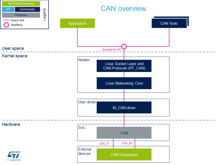
2. System overview[edit | edit source]
2.1. Component description[edit | edit source]
From user space to hardware
- Application (User space)
Application to read/write data on the SocketCAN interface for communication with external devices connected on the CAN network (such as can-utils).
- CAN tools (User space)
Set of utilities for configuring and enabling SocketCAN interface (such as iproute2).
- SocketCAN (Kernel space)
Socket interface with specific CAN options which builds upon the Linux network layer.
- Linux Socket Layer and CAN Protocols (PF_CAN) (Kernel space)
The protocol family, PF_CAN[4], provides an API for transport protocol modules to register and the structures to enable different CAN protocols on the bus.
- Linux Networking Core (Kernel space)
Kernel network layer that adapts the message to the transport protocol in use. The network subsystem of the Linux kernel is designed to be completely protocol-independent.
- M_CAN Driver (Kernel space)
Driver implemented as a network interface for Bosch M_CAN controller[5].
- CAN (Hardware)
This is the CAN Core IP.
- CAN Transceiver (Hardware)
Interface between the CAN protocol controller and the physical wires of the CAN bus lines.
2.2. API description[edit | edit source]
The SocketCAN interface API description can be found in kernel documentation [3].
3. Configuration[edit | edit source]
3.1. Kernel configuration[edit | edit source]
Activate the CAN driver in kernel configuration with Linux Menuconfig tool.
For compiling M_CAN driver, select "Bosch M_CAN devices":
 [*] Networking support  --->
        <*>   CAN bus subsystem support  --->
                CAN Device Drivers  --->
                        <*>   Bosch M_CAN support
                        <*>       Bosch M_CAN support for io-mapped devices
M_CAN driver is activated by default in ST deliveries.
3.2. Device tree configuration[edit | edit source]
CAN generic DT bindings:
- The M_CAN device tree bindings[6] describe all the required and optional properties.
Detailed DT configuration for STM32 internal peripherals:
4. How to use the framework[edit | edit source]
The CAN device must be configured via netlink interface. The following articles give user space examples of how to set up a SockeCAN interface (and configure settings like bit-timing parameters) and how to send/receive data on the CAN bus.
4.1. How to set up a SocketCAN interface[edit | edit source]
How to set up a SocketCAN interface
4.2. How to send/receive CAN data[edit | edit source]
How to send or receive CAN data
5. How to trace and debug the framework[edit | edit source]
5.1. How to trace[edit | edit source]
CAN Framework, specifically M_CAN driver, print out info and error messages. You can display them with dmesg command:
dmesg | grep m_can
[    1.327824] m_can 4400e000.can: m_can device registered (irq=30, version=32)
[   25.560759] m_can 4400e000.can can0: bitrate error 0.3%
[   25.564630] m_can 4400e000.can can0: bitrate error 1.6%
5.2. How to monitor CAN bus[edit | edit source]
You can use the CAN FD adapter PCAN-USB Pro FD[7] to connect a computer to the CAN network via USB. The PCAN-View software provided with the tool is a monitoring program that allows to supervise the data flow on the CAN network and to detect frame errors.
6. Source code location[edit | edit source]
The source files are located inside the Linux kernel.
- PF_CAN: af_can.c[4]
- M_CAN driver: m_can.c[5]
7. To go further[edit | edit source]
CAN bit timing calculation plays an important role in ensuring performance of CAN network. To avoid transmission errors, the bit timing must be configured properly.
For more information about CAN bit timing:
- Computation of CAN Bit Timing Parameters Simplified[8], from the CAN in Automation group (CiA)
- The Configuration of the CAN Bit Timing[9], from Bosch documentation
8. References[edit | edit source]
- ↑ CAN FD - The basic idea, from the CAN in Automation group (CiA)
- ↑ CAN protocol implementations, from the CAN in Automation group (CiA)
- ↑ 3.0 3.1 Kernel SocketCAN documentation , Linux Foundation
- ↑ 4.0 4.1 4.2 net/can/af_can.c , Protocol family CAN core module
- ↑ 5.0 5.1 drivers/net/can/m_can/ , Driver for Bosch M_CAN controller
- ↑ Documentation/devicetree/bindings/net/can/bosch,m_can.yaml M_CAN device tree bindings
- ↑ PCAN-USB Pro FD description, by PEAK System
- ↑ Computation of CAN Bit Timing Parameters Simplified, from the CAN in Automation group (CiA)
- ↑ The Configuration of the CAN Bit Timing, from Bosch documentation