This article gives information about the Linux® PCIe framework.
It explains how to activate the PCIe interface and, based on examples, how to access it from user space.
1. Framework purpose[edit | edit source]
The PCIe (peripheral component interconnect express) Linux® framework supports two types of operating modes:
- Root complex controller mode to connect peripheral devices.
- Endpoint controller mode to be used as a peripheral.
Linux can be used on the host machine. In this case various type of PCIe peripherals can be plugged in, such as:
- Mass storage (SATA or USB bridge...)
- Network interface (Ethernet, wifi...)
Linux can also be used as a device on the peripheral side.
2. System overview[edit | edit source]
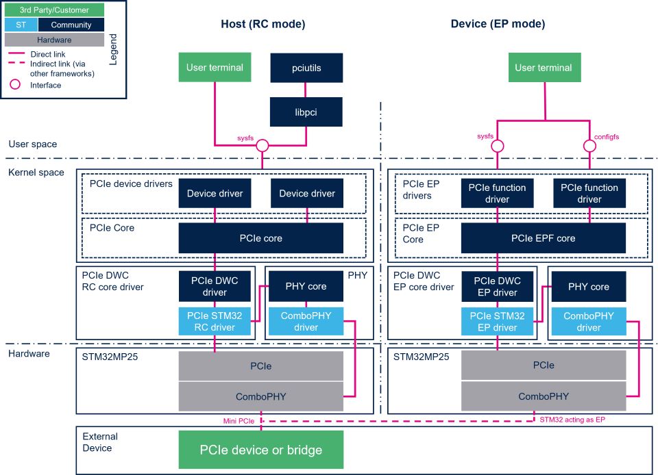
2.1. Component description[edit | edit source]
- PCIe userland (user space)
- Host-side userland
- - pciutils[1] is a set of PCI utilities for collecting information about the PCI devices that are connected to the PCIe host.
- - One of the well-known utilities is lspci, used to display information about PCIe buses and the devices connected to them.
- Common userland
- - sysfs provides an information interface available through the user terminal. See How to monitor with sysfs below.
- PCIe framework (kernel space): PCIe RootComplex, which rely on the PCIe core with specific APIs to support PCIe devices.
- Host-side provides the API interface to class drivers and forwards the request from class drivers to host controller driver.
- PCIe controller drivers (kernel space)
- PCIe host controller drivers such as STM32 PCIe PCIe host controllers in the PCIe host-side framework. STM32 PCIe uses kernel community drivers (kernel space), based on the PCIe framework.
- PCIe controller drivers can rely on the Generic PHY framework to manage the physical layer for PCIe data transmissions and reference clock. STM32 ComboPHY PHY provider is a PHY driver in the generic PHY framework:
2.2. API description[edit | edit source]
The PCIe EPC library describes the set of API used to write a PCIe driver for the controller operating in end point mode. See PCI kernel documentation for more details on API functions.
3. Configuration[edit | edit source]
3.1. Kernel configuration[edit | edit source]
PCIe support, STM32 PCIe driver is activated by default in ST deliveries. Nevertheless, if a specific configuration is required, this section indicates how the PCIe framework can be activated/deactivated in the kernel.
Activate PCI support (CONFIG_PCI=y) in the kernel configuration with the Linux menuconfig tool: Menuconfig or how to configure kernel then select:
Device Drivers  --->
 [*] PCI support  --->
Then activate the PCI controllers drivers.
To activate the STM32 PCIe driver in host mode, select:
Device Drivers  --->
   --- PCI support
   ---- PCI controller drivers
   ----- DesignWare PCI Core Support
   ------ STMicroelectronics PCIe Controller Host Mode for STM32 MP25
To activate the STM32 PCIe driver in endpoint mode, select:
Device Drivers  --->
   --- PCI support
   ---- PCI controller drivers
   ----- DesignWare PCI Core Support
   ------ STMicroelectronics PCIe Controller Endpoint Mode for STM32 MP25
Then to activate the STM32 COMBOPHY driver, select:
  Device Drivers  --->
  PHY Subsystem  --->
    <*> STMicroelectronics ComboPHY driver for STM32 MP25
3.2. Device tree configuration[edit | edit source]
Detailed DT configurations for STM32 PCIe internal peripherals:
- For STM32 PCIe host controller: PCIe device tree configuration
- For STM32 COMBOPHY PHY: ComboPHY device tree configuration
4. How to use the framework[edit | edit source]
4.1. How to use the root complex framework[edit | edit source]
4.1.1. How to list PCIe devices[edit | edit source]
lspci displays information about the attached PCIe bridges and devices.
The example above shows a PCIe SATA controller, and a WIFI network controller device attached to a four ports PCIe switch.
lspci
00:00.0 PCI bridge: Synopsys, Inc. Device 0550 (rev 01)
01:00.0 PCI bridge: ASMedia Technology Inc. ASM1184e 4-Port PCIe x1 Gen2 Packet Switch
02:01.0 PCI bridge: ASMedia Technology Inc. ASM1184e 4-Port PCIe x1 Gen2 Packet Switch
02:03.0 PCI bridge: ASMedia Technology Inc. ASM1184e 4-Port PCIe x1 Gen2 Packet Switch
02:05.0 PCI bridge: ASMedia Technology Inc. ASM1184e 4-Port PCIe x1 Gen2 Packet Switch
02:07.0 PCI bridge: ASMedia Technology Inc. ASM1184e 4-Port PCIe x1 Gen2 Packet Switch
03:00.0 SATA controller: ASMedia Technology Inc. ASM1062 Serial ATA Controller (rev 02)
05:00.0 Network controller: Qualcomm Atheros QCA6174 802.11ac Wireless Network Adapter (rev 32)
 Information Information
|
| The number format is represented in the Bus:Device.Function format (as logically found during the Linux enumeration probe). |
In the example:
- 00:00.0 represents the host PCIe RC controller.
- 01:00.0 represents the inbound switch interface.
- 02:01-07 represents the outbound switch interface with four ports numbered 01,03,05,07.
- 03:00.0 is the SATA controller outbound interface.
- 05:00.0 is the WIFI controller outbound interface.
The PCIe tree structure is best shown with the -P option:
lspci -P
00:00.0 PCI bridge: Synopsys, Inc. Device 0550 (rev 01)
00:00.0/00.0 PCI bridge: ASMedia Technology Inc. ASM1184e 4-Port PCIe x1 Gen2 Packet Switch
00:00.0/00.0/01.0 PCI bridge: ASMedia Technology Inc. ASM1184e 4-Port PCIe x1 Gen2 Packet Switch
00:00.0/00.0/03.0 PCI bridge: ASMedia Technology Inc. ASM1184e 4-Port PCIe x1 Gen2 Packet Switch
00:00.0/00.0/05.0 PCI bridge: ASMedia Technology Inc. ASM1184e 4-Port PCIe x1 Gen2 Packet Switch
00:00.0/00.0/07.0 PCI bridge: ASMedia Technology Inc. ASM1184e 4-Port PCIe x1 Gen2 Packet Switch
00:00.0/00.0/01.0/00.0 SATA controller: ASMedia Technology Inc. ASM1062 Serial ATA Controller (rev 02)
00:00.0/00.0/05.0/00.0 Network controller: Qualcomm Atheros QCA6174 802.11ac Wireless Network Adapter (rev 32)
To limit lspci to a specific device, use its BDF address: for example, to check the SATA speed information:
lspci -vv -s 03:00.0 | grep Speed
LnkCap: Port #1, Speed 5GT/s, Width x1, ASPM not supported
LnkSta: Speed 5GT/s, Width x1
LnkCtl2: Target Link Speed: 5GT/s, EnterCompliance- SpeedDis-
4.1.2. How to wake up from PCIe[edit | edit source]

|
Coming soon |
4.1.3. How to configure ASPM[edit | edit source]
4.2. How to use the endpoint framework[edit | edit source]
The Linux PCIe endpoint framework is based on the EPC (End Point Controller Library) and the EPF (End Point Function Library). The EPF needs to initialise the function's configuration space to bind the function driver to the controller.
In this document, the pci-epf-test function device is used as an example. A PCIe EP framework involves 2 drivers:
- The PCIe EP function driver. The driver exposes the devices resources to the host enumeration and enables communication (here for a test protocol) with the host driver. Enabled with:
Device Drivers  --->
   --- PCI support
   ---- PCI Endpoint
   ----- PCI Endpoint Support
   ------ PCI Endpoint Test Driver
- The PCIe Host side enabled with
Device Drivers  --->
   --- Misc devices
   ---- PCI Endpoint Test driver
PCIe EP driver setup implies programming its configuration space, binding its driver and then starting the link with the Host:
4.2.1. Hardware Requirements[edit | edit source]
- A PCIe Host
- A Mini-PCie cable (point-to-point connection, not extension)
- The STM32MP257F-EV1
 board configured as an endpoint
When configured as an endpoint, the PCIe controller support the shared 100Mhz reference clock model. To get the reference clock from the host, the REFCLK must be routed from the PCI REFCLK_N/P pins. On the stm32mp-ev1 (revD) board, this can be done by removing the 0 Ohms resistors R87/R88/R89/R90 and connect R288/R328

4.2.2. PCIe EP device tree configuration[edit | edit source]
To configure the PCIe controller in endpoint mode, refer to the PCIe device tree configuration article.
4.2.3. PCIe EP Software configuration[edit | edit source]
- Initialize the PCIe device function registers
cd /sys/kernel/config/pci_ep/
mkdir functions/pci_epf_test/func1
echo 0x104a > functions/pci_epf_test/func1/vendorid
echo 0xccff > functions/pci_epf_test/func1/deviceid
echo 8 > functions/pci_epf_test/func1/msi_interrupts
The 6 programmable BARs are defined in hardware with the following 32-bit, non-prefetchable values :1M,64K,1M,1M,1M,1M. But up the 4 memory regions can be simultaneously allocated.
| Information
|
| To reprogram the BARs with different values, see the pci_epc_set_bar API framework. |
4.2.4. PCIe EP Start[edit | edit source]
- Bind to the PCIe controller:
ln -s functions/pci_epf_test/func1 controllers/48400000.pcie-ep/
- Start the link training with the host
echo 1 > /sys/kernel/config/pci_ep/controllers/48400000.pcie-ep/start
All those steps can be put into an init_ep.sh script and automatically executed with an udev rule when the pci-epf-drive is probed
root@stm32mp2:~# cat /etc/udev/rules.d/99-pcie-ep.rules
KERNEL=="pci_epf_test", RUN+="/home/root/init_ep.sh"
At this point, it's possible to start enumeration on the Host :
root@stm32mp2:~# echo 1 > /sys/bus/pci/rescan
root@stm32mp2:~# lspci
00:00.0 PCI bridge: Synopsys, Inc. Device 0550 (rev 01)
01:00.0 Unassigned class [ff00]: STMicroelectronics Device ccff
5. How to test the PCIe EP[edit | edit source]
If the device ID has been correctly configured as above, which is confirmed by lspci. make sure that the pci_endpoint_test driver module has been loaded: This driver uses the endpoint framework to test a number of EP unitary features with pcitest user tool
5.1. Sample usage[edit | edit source]
root@stm32mp2:~# pcitest -h
usage: pcitest [options]
Options:
        -D <dev>                PCI endpoint test device {default: /dev/pci-endpoint-test.0}
        -b <bar num>            BAR test (bar number between 0..5)
        -m <msi num>            MSI test (msi number between 1..32)
        -x <msix num>           MSI-X test (msix number between 1..2048)
        -i <irq type>           Set IRQ type (0 - Legacy, 1 - MSI, 2 - MSI-X)
        -e                      Clear IRQ
        -I                      Get current IRQ type configured
        -d                      Use DMA
        -l                      Legacy IRQ test
        -r                      Read buffer test
        -w                      Write buffer test
        -c                      Copy buffer test
        -s <size>               Size of buffer {default: 100KB}
        -h                      Print this help message
root@stm32mp2:~# pcitest -b 0
BAR0:           OKAY
root@stm32mp2:~# pcitest -m 1
MSI1:           OKAY
root@stm32mp2:~# pcitest -r
READ ( 102400 bytes):           OKAY
root@stm32mp2:~# pcitest -w
WRITE ( 102400 bytes):          OKAY
root@stm32mp2:~# pcitest -rd
READ ( 102400 bytes):           OKAY
root@stm32mp2:~# pcitest -d
root@stm32mp2:~# pcitest -r
READ ( 102400 bytes):           OKAY
6. How to trace and debug the framework[edit | edit source]
6.1. How to monitor[edit | edit source]
6.1.1. How to monitor with sysfs[edit | edit source]
The same BDF format can be used to display information about devices.
cat /sys/bus/pci/devices/0000:03:00.0/current_link_speed
5.0 GT/s PCIe
6.1.2. Other ways of monitoring[edit | edit source]
6.2. How to trace[edit | edit source]
6.2.1. Activating PCIe framework debug messages[edit | edit source]
A detailed dynamic trace is available in How to use the kernel dynamic debug.
 echo 8 > /proc/sys/kernel/printk
 echo "file drivers/pci/* +p" > /sys/kernel/debug/dynamic_debug/control
This command enables all the traces related to the PCIe core and drivers at runtime.
A finer selection can be made by choosing only the files to trace.
| Information
|
| Reminder: loglevel needs to be increased to 8 either by using boot arguments or by sending the dmesg -n 8 command from the console. |
Dynamic debug can also be activated at boot from the boot command line, for instance:
loglevel=8 dyndbg="file drivers/pci/* +p"
6.3. How to debug[edit | edit source]
6.3.1. AER error messages[edit | edit source]
Link errors are notified on the console with AER messages. Such errors usually indicate wrong electrical quality and can lead to speed demotion (demoted to Gen1 during link training) or timeouts due to the error logs on the display.
Recovered AER messages can flood the console and prevent correct use of the PCIe device. They can be disabled with the pci=noaer command line parameter. In this case, link error statistics are logged in the host aer sysfs entries:
cat /sys/bus/pci/devices/0000:00:00.0/aer_dev_fatal
Undefined 0
DLP 0
SDES 0
TLP 0
FCP 0
CmpltTO 0
CmpltAbrt 0
UnxCmplt 0
RxOF 0
MalfTLP 0
ECRC 0
UnsupReq 0
ACSViol 0
UncorrIntErr 0
BlockedTLP 0
AtomicOpBlocked 0
TLPBlockedErr 0
PoisonTLPBlocked 0
TOTAL_ERR_FATAL 0
The AER cause can be a failing device, or an unsatisfactory electrical link (loss, jitter, extern aggressor, ...) electrical compliance characterization must be performed, and the reference clock eye diagram performed to check jitter or power ranges characteristics.
6.3.2. How to trace using a protocol analyzer[edit | edit source]
Link-up recoveries or protocol error events can also be debugged with the PCIe protocol analyzer. With the help of an exerciser, a PCIe protocol analyzer is a PCIe traffic sniffer that decodes PCIe packets and displays bus states and packets sent. Refer to the PCIe protocol analyzer user manual.
6.4. Troubleshooting[edit | edit source]
Some common issues related to the PCIe feature are listed in STM32 PCIe troubleshooting.
7. Source code location[edit | edit source]
The source files are located inside the Linux kernel.
- The PCIe framework is under drivers/pci/ .
- The drivers used for STM32 PCIe are under drivers/pci/controller/dwc/pcie-stm32.c , drivers/pci/controller/dwc/pcie-stm32-ep.c .
- The drivers used for STM32 ComboPHY are under drivers/phy/st/phy-stm32-combophy.c .
8. To go further[edit | edit source]
PCIe specifications can be found in PCISIG[2].
Very useful documentation can be found in the Linux kernel PCI documentation.
An introduction to PCIe driver provided by Bootlin PCIe drivers[3].
9. References[edit | edit source]