This article describes how the STM32 MPU Embedded Software distribution maps the various software memory needs in internal and external volatile memories.
1. Overview[edit | edit source]
This article shows the default memory mapping defined by STMicroelectronics in STM32MPU Embedded Software. It uses a subset of all memory regions that are exposed at hardware level: customers may use other memory regions or aliases that are not shown here but are described in the STM32MP15 reference manuals.
2. Arm core characteristics[edit | edit source]
The integration of Arm® Cortex® cores sets some constraints on the device memory mapping: the main ones are listed in this article.
2.1. Reset address[edit | edit source]
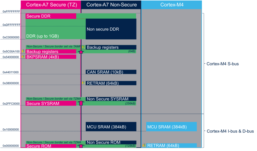
Arm® Cortex® cores start running from address 0x00000000 on reset, which is why this address respectively points to:
- The ROM code on the Cortex-A7 side. This read-only memory embeds the boot code that is executed when the platform boots (and executes the boot chain) or wakes up from low power STANDBY mode.
- The Retention RAM on the Cortex-M4 side. This needs to be loaded by the Cortex-A7 before releasing the Cortex-M4 reset (in the RCC) and getting it running. This is done by Linux Cortex-M coprocessor management, by default.
Note: since the Cortex-A7 has its ROM code mapped at address 0x00000000, it uses a hardware alias to access the retention RAM at address 0x38000000
2.2. Cortex-M4 multiple ports[edit | edit source]
The Cortex-M4 is connected to the interconnect (ML-AHB) via three ports, listed below and shown in the following figure:
- I-bus is used to fetch code instructions in the 0x00000000--0x1FFFFFFF address range
- D-bus is used to read/write data in the 0x00000000--0x1FFFFFFF address range
- S-bus is used for all accesses in the 0x20000000--0xFFFFFFFF address range; all STM32MP15 internal peripherals registers are mapped in this range.
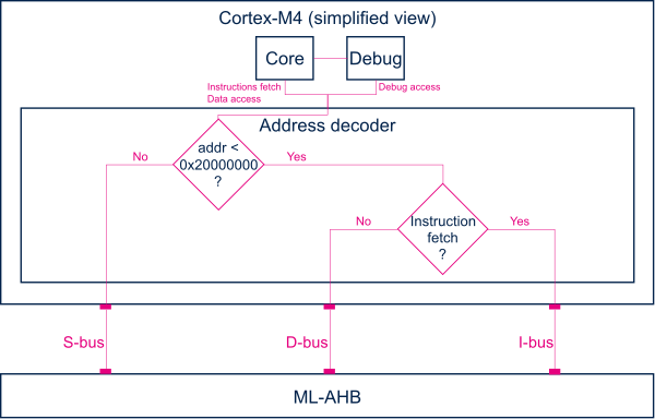
Balancing the Cortex-M4 firmware accesses among those ports allows tuning of the system performance, which is why the MCU SRAM is defined in the first address range (from 0x10000000), but is also visible in the second range (from 0x30000000) in the STM32MP15 reference manuals.
Nevertheless, it is important to notice that the Cortex-M4 embedded in the STM32MP15 only allows hardware breakpoints to be set on the address range covered by the I-bus. Thus any code accessed via the S-bus has to be debugged through software breakpoints.
3. Memory mapping[edit | edit source]
3.1. Overall memory mapping[edit | edit source]
The memory mapping below is a subset of all regions that are exposed at hardware level: it shows the default configuration used in OpenSTLinux but the customer may choose a different mapping to take advantage of other address ranges defined in STM32MP15 reference manuals.
3.2. BKPSRAM[edit | edit source]
In the STM32MPU Embedded Software architecture, the BKPSRAM internal memory is used as follows:
- At boot time: not used during a cold boot
- At runtime:
- DDR off in Standby: not used
- DDR in self-refresh in Standby: contains the low-power context used by the runtime secure monitor (the Trusted Firmware-A (TF-A) BL2 as the FSBL or the OP-TEE secure OS) during wake-up from Standby low-power mode. Refer to STM32MP1 power overview for details.
3.3. SYSRAM[edit | edit source]
At boot time, the ROM code configures the SYSRAM internal memory as a secure peripheral during execution. It uses 9 Kbytes at the beginning of SYSRAM to store its read and write data. The first 512 bytes of SYSRAM store the boot context. The boot context contains information such as the selected boot device and pointers to ROM code exported services that are used for secure boot authentication.
The ROM code loads Trusted Firmware-A (TF-A) as FSBL after the boot context into the remaining 247 Kbytes of SYSRAM, and then transfers Cortex®-A7 core 0 execution to this FSBL.
At runtime, SYSRAM is secure and can contain:
- OP-TEE secure OS firmware
- Trusted Firmware-A (TF-A) for low-power purposes when OP-TEE secure OS is loaded in DDR
The following figure shows the evolution of the SYSRAM mapping during boot flow.

Refer to boot chain for details.
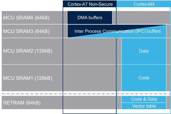
3.4. RETRAM and MCU SRAM[edit | edit source]
The figure below is a zoom of the RAM areas that are shared between the Cortex-A7 nonsecure and the Cortex-M4. This mapping is STMicroelectronics' default implementation that can be freely adapted by customers to fit to other needs.
[edit | edit source]
As described in STM32MP15 MCU SRAM internal memory, ST has defined a memory mapping to be able to enable all the possible use cases in parallel but this can be customized depending on customer use cases.
3.5.1. Overview[edit | edit source]
- RETRAM is not used except for the vector table which must be stored at address 0. The rest of this memory section can be used for any purpose.
- MCU SRAM1 (Code) and SRAM2 (Data) sizes can be tuned depending on user needs to better use physical area of 256KB.
- MCU SRAM3 (IPC Buffers) can be used for other purpose if IPC is not used
- MCU SRAM4 (DMA) can be used for other purpose if DMA1 and/or DMA2 is not used in chained mode (using MDMA)
3.5.2. How to do that in practice[edit | edit source]
The memory usage is defined in both Cortex contexts:
- on Cortex-A7: in Linux device tree, using Reserved_memory mechanism
- on Cortex-M4: in the linker script
To ensure the consistency of the system, both memory declarations have to be updated according to the expected configuration.
3.5.2.1. RETRAM[edit | edit source]
By default the RETRAM is reserved for the Cortex-M4 firmware and only the vector table uses it. The base address is fixed, the vector table section of the M4 firmware needs to be at this place but other sections may be added on top.
- Linux Device tree
- "retram" memory region declaration (no update needed):
retram: retram@0x38000000 {
	compatible = "shared-dma-pool";
	reg = <0x38000000 0x10000>;
	no-map;
};
- No update needed for m4_proc node.
&m4_rproc {
	memory-region = <&retram>, <&mcuram>, <&mcuram2>, <&vdev0vring0>,
			<&vdev0vring1>, <&vdev0buffer>;
	ranges =  <0x00000000 0x38000000 0x10000>,
			 <0x30000000 0x30000000 0x60000>,
			 <0x10000000 0x10000000 0x60000>;
- Cortex-M4 STM32Cube firmware
- In STM32Cube linker script definition (.ld): keep vector table "m_interrupts" but any new section can be added on top to use RETRAM free memory space:
MEMORY
{
    m_interrupts (RX)  : ORIGIN = 0x00000000, LENGTH = 0x00000298
    m_any_section .... : ..................
}
3.5.2.2. MCU SRAM4[edit | edit source]
By default the MCU SRAM4 is reserved for DMA chaining for Linux features. It can be freed for some other purposes by removing following:
- Linux device tree
- Remove followings declarations:
&sram {
    dma_pool: dma_pool@0 {
    reg = <0x50000 0x10000>;
    pool;
};
&dma1 {
	sram = <&dma_pool>;
};

&dma2 {
	sram = <&dma_pool>;
};
3.5.2.3. MCU SRAM3[edit | edit source]
By default the MCU SRAM3 is reserved for the IPC. It can be freed for some other purposes by removing following:
- Linux device tree
- Remove followings memory region declarations:
		vdev0vring0: vdev0vring0@10040000 {
			compatible = "shared-dma-pool";
			reg = <0x10040000 0x1000>;
			no-map;
		};

		vdev0vring1: vdev0vring1@10041000 {
			compatible = "shared-dma-pool";
			reg = <0x10041000 0x1000>;
			no-map;
		};

		vdev0buffer: vdev0buffer@10042000 {
			compatible = "shared-dma-pool";
			reg = <0x10042000 0x4000>;
			no-map;
		};
- Remove associated reference in m4_rproc node:
&m4_rproc {
	memory-region = <&retram>, <&mcuram>, <&mcuram2>,
			 <&vdev0vring0>, <&vdev0vring1>, <&vdev0buffer;
	ranges =  <0x00000000 0x38000000 0x10000>,
			 <0x30000000 0x30000000 0x60000>,
			 <0x10000000 0x10000000 0x60000>;
- Cortex-M4 STM32Cube firmware:
- Must be aligned with STM32Cube linker script definition (.ld), remove "m_ipc_shm":
MEMORY
{
    m_ipc_shm    (RW)  : ORIGIN = 0x10040000, LENGTH = 0x00008000
}
3.5.2.4. MCU SRAM1 & SRAM2[edit | edit source]
By default the MCU SRAM1 & SRAM2 are reserved for the STM32Cube firmware. This can be optimized depending on the firmware needs.
- Linux device tree
- Only one section is declared for STM32Cube firmware code and data in Linux device tree
- Notice that the MCURAM is aliased so accessible at addresses 0x10000000 or 0x30000000. In consequence mcuram and mcuram2 memory sections definitions have to be coherent.
	mcuram: mcuram@ 0x30000000 {
		compatible = "shared-dma-pool";
		reg =  <0x30000000 0x40000>; /* define memory base and size for Cortex-M4 firmware*/
		no-map;
	};
	mcuram2: mcuram2@0x10000000 {
		compatible = "shared-dma-pool";
		reg = <0x10000000 0x40000>; /* define memory base and size for Cortex-M4 firmware*/
		no-map;
	};
- No update needed for m4_proc node.
&m4_rproc {
	memory-region = <&retram>, <&mcuram>, <&mcuram2>, <&vdev0vring0>,
			<&vdev0vring1>, <&vdev0buffer>;

	ranges = <0x00000000 0x38000000 0x10000>,
			 <0x30000000 0x30000000 0x60000>,
			 <0x10000000 0x10000000 0x60000>;
- Cortex-M4 STM32Cube firmware
- The memory mapping you have defined on Linux side (freed for M4 usage) needs to be consistent with STM32Cube linker script definition (.ld):
MEMORY
{
 m_interrupts (RX)  : ORIGIN = 0x00000000, LENGTH = 0x00000298
 m_text       (RX)  : ORIGIN = 0x10000000, LENGTH = 0x00020000
 m_data       (RW)  : ORIGIN = 0x10020000, LENGTH = 0x00020000
 m_ipc_shm    (RW)  : ORIGIN = 0x10040000, LENGTH = 0x00008000
}
3.6. DDR mapping[edit | edit source]
STM32MPU Embedded Software defines a generic DDR mapping that supports DDR sizes from 256 MB to 1 GB. This mapping demonstrates all features of STM32MPU Embedded Software.
- The last 32 MB are reserved for OP-TEE secure OS firmware.
- The rest of DDR is allocated to the Linux kernel and applications.
The following figure shows how the 1 GB DDR mapping changes during the boot sequence.

Arm® is a registered trademark of Arm Limited (or its subsidiaries) in the US and/or elsewhere. ![]()
Arm® is a registered trademark of Arm Limited (or its subsidiaries) in the US and/or elsewhere. ![]()