1. Purpose[edit | edit source]
This article proposes some guidelines in order to determine the best low-power strategy for your STM32 MPU product.
The power consumption of the system and its components are affected by the software load put on the hardware components, such as CPU cores, GPU, and peripherals, it is directly related to the use-case application but also affected by its fine-tuning and condition (environmental temperature, connected peripherals). It is suggested that a customer estimates its power consumption under its own particular use cases before designing hardware based on this data.
2. Hardware design[edit | edit source]
The STM32 MPU requires main supply as VDD, VDDA18AON, VDDCPU, VDDCORE but uses also independent supplies for other internal power domain as IO domains.
The choice of STM32 MPU power suppliers have a direct impact of the low power strategy; the product has low power mode restrictions when the supplies cannot be controlled by STM32 MPU external control signals.
A STMicroelectronics multi-output power management ICs in STPMIC family[1](STPMIC1, STPMIC1L, STPMIC2L, STPMIC25) is the recommended solution to supply each power rail required by a STM32 MPU hardware design:
- it is fully integrated and optimized for powering designs with the STM32 Arm® Cortex® MPUs
 , even for complex power demands or for power-up/down sequencing
 - it saves board space and BOM cost vs discrete solution
- the STPMIC family is supported in OpenSTLinux
| PMIC | #DC/DC[2] #LDO #SW |
Description | Restrictions without additional regulator | |
|---|---|---|---|---|
| companion chip for STM32MP1 series |
STPMIC1[3] | 4 Buck 1 Boost[4] |
Optimized BOM for board level applications QFN 5x6mm |
|
| STPMIC1L[5] | 2 Buck 4 LDO |
Best cost with Minimum system BOM QFN 4x4mm |
STM32MP1 series: No CPU overdrive | |
| companion chip for STM32MP2 series |
STPMIC25[6] | 7 Buck 9 LDO |
Optimized BOM for board level applications QFN 6.5x6.5mm |
|
| STPMIC2L[7] | 3 Buck 7 LDO |
Optimized for standard system BOM QFN 5x5mm |
STM32MP25x lines |
The integration of STPMIC in the hardware design is directly linked to the STM32 MPU boot and low power sequences:
- on STM32MP1 series with the STM32 MPU pins - PWR_ON, PWR_LP - connected to PWRCTRL pins
- on STM32MP2 series with the STM32 MPU pins - PWR_ON, PWR_CPU_ON, PWR_LP, NRSTC1MS - connected to STPMIC power control pins.
VDDCPU and VDDCORE are controlled for low power modes (switched off or reduced) by the STM32 MPU firmware with these STM32 MPU pins and with PWR.
This hardware design choice, which is connected to the STPMIC pins, defines how the alternate STPMIC configuration can be used by the software and can limit the low power strategy (for example, VDDCPU cannot be reduced for LPLV-Stop1 in STM32MP2 OpenSTLinux).
You can find more details on the hardware development, including the required power supplies, and examples of integration with PMIC companion chip, in the next application notes:
- AN5474 - Getting started with STM32MP13 series hardware development
- AN5031 - Getting started with STM32MP15 Series hardware development
- AN5489 - Getting started with STM32MP23/25xx MPUs hardware development
- STPMIC application notes
The consumption on the STM32 MPU supplies must be optimized during the hardware design:
- reduced consumption on main supplies, which are required in low power modes (DDR, IO, backup domain)
- it is recommended to use a 1.8V I/Os voltage range, supplied by VDD, to reduce the system power consumption.
- the external DDR memory is controlled by the STM32 MPU firmware through an external regulator (for example with STPMIC); when the system enters low-power modes the firmware configure the DDR in self refresh mode and lets it powered.
The DDR power consumption has to be considered at system level and depends on the selected DDR memory (refer to your memory provider datasheet),
so it is recommended to use LPDDR device, instead of DDR, as main memory to reduce the system power consumption in low power mode.
- use separate regulator for each power rail required by a STM32 MPU to allow deactivation when the associated features are not used
for example:- VDDGPU deactivated when GPU is not used
- USB power supply deactivated when USB cable is unplugged
- external devices (flash, camera display, ...) are also supplied with external regulators.
It is recommended to have a separate regulator for each device: supplies can be deactivated when associated devices is not used to reduce system consumption.- power supply for persistence storage - as SDCard, eMMC, NOR or NAND - can be deactivated during inactivity period but power cycle on boot device must also be managed for ROM code execution on system boot after system reset or, when it is needed, after exit of low power mode.
The wake-up sources used for your design must be selected to allow the deepest low power mode, in particular it is preferable to use PWR WKUP pins vs GPIO.
The content of the backup domain (RTC, backup registers, LSE, LSI, backup ram, ...) is preserved when VDD is turned off only if the VBAT pin is connected to a optional standby voltage supply. This backup supply must respect the power consumption in low power mode and preserve the product lifetime (for example with coincell, its charge must be preserved when the product is powered off but plugged on external supply).
3. Software design[edit | edit source]
To reduce the power consumption, the STM32 MPU firmware must:
- Activate device only when they are used (internal peripheral, including clocks, and external peripheral, including power supply)
- Use CPU subsystem low power modes for Idle period (WFI, CSleep)
- Use the correct GPIO configuration to avoid leakage for low power mode
- Use the deepest and possible low power modes (with wake-up and latency constraints).
Refer to the power overview to discover the corresponding software architecture with OpenSTLinux.
To go deeper, you can also consider to use the STM32Cube firmware running on the Arm® Cortex®-M processor in the internal memory to avoid usage of external DDR when this firmware is required by your product, even it is not the default configuration in OpenSTLinux.
4. On STM32MP13x lines [edit | edit source]
4.1. STM32MP13 power supplies[edit | edit source]
It is important to understand the perimeter of the three STM32MP13 main power supplies:
- VDD supplies I/Os and analog components such as reset, power management, oscillators and PLLs. VDD is present as far as the STM32MP13 is not in Off or VBAT mode. For a given system, VDD voltage is fixed and usually chosen between 1.8 V to 3.3 V typical.
- VDDCORE supplies the digital core domain, except the Arm® Cortex®-A7 CPU, and must be present after VDD at start up. Depending on the system low-power mode, VDDCORE voltage varies between switched off (0 V), the retention voltage (0.9 V) and the nominal voltage (1.25 V). The mapping of these voltage levels to the low-power modes is shown in the next paragraph.
- VDDCPU supplies the Arm® Cortex®-A7 CPU, and must be present after VDD at start up. There is no precedence constraint between this supply and VDDCORE. Depending on the system low-power mode, VDDCPU voltage varies between switched off (0 V), the retention voltage (0.9 V) and the nominal voltage (1.25 V). The mapping of these voltage levels to the low-power modes is shown in the next paragraph.
For more information, refer to the PWR chapter of the STM32MP13 Reference Manual and to the STM32MP13 Datasheet.
4.2. STM32MP13 low-power modes[edit | edit source]
Starting from the Run mode, various actions can be taken to reduce the processor power consumption when all tasks have been completed:
- Stop the high-speed clock sources (PLLs/HSI/HSE/CSI): this corresponds to the Stop mode where the VDDCORE and VDDCPU external regulators are kept at their nominal voltages. The regulators can even be switched in low-power mode in order to reduce their power consumptions: this is the LP-Stop mode.
- Stop the high-speed clock sources (PLLs/HSI/HSE/CSI) and reduce VDDCORE and VDDCPU voltages to their retention values: this is the LPLV-Stop mode, that enables to consume low power while maintaining the content of all the registers and internal memories.
- Stop the high-speed clock sources (PLLs/HSI/HSE/CSI), reduce VDDCORE voltage to its retention value and switch off VDDCPU: this is the LPLV-Stop2 mode, that enables to consume the minimum power while maintaining the content of all the registers and internal memories, except the CPU sub-system ones.
- Stop the high-speed clock sources (PLLs/HSI/HSE/CSI) and switch off VDDCORE and VDDCPU: this is the Standby mode, where the content of all registers and internal memories is lost, apart from the ones that are in VSW domain that is supplied by VDD (when present) or VBAT (in VBAT mode). In particular, notice that the Backup registers and the BKPSRAM are in the VSW domain. Please also note that PWR and RCC both have some registers in the VSW (kept during Standby) and VDD (lost during Standby) domains.
One or several wake-up source(s) are used to exit from the above low-power modes and come back to Run mode. Not all internal peripherals are able to wake up from low-power modes. Table Functionalities depending on system operating mode located in the PWR chapter of the STM32MP13 Reference Manual, shows the wake-up capability of each peripheral. This is summarized in the figure in the following paragraph.
When the processor is put in one of these low-power modes, the external RAM (DDR) is usually put in Self-Refresh mode in order to keep its content whereas most of the STM32MP13 is no more active (no more clock generated for the DDR, no more Auto-refresh commands). This extra power consumption has to be considered at system level and depends on the selected DDR memory (refer to your memory provider datasheet).
The main side effect of using low-power modes is the wake-up time required to restore the system to a full running state (Run mode): the deepest you slept and the longest it needs to wake up. The next chapter illustrates this in order to allow you to make the best choice for your product.
4.3. STM32MP13 low-power strategy[edit | edit source]
4.3.1. Overview[edit | edit source]
The figure below shows, for each low-power mode:
- The peripherals that can be used as wake-up sources (grey boxes)
- The STM32MP13 typical power consumption (on the left)
- The system wake-up times in various configurations (on the right)
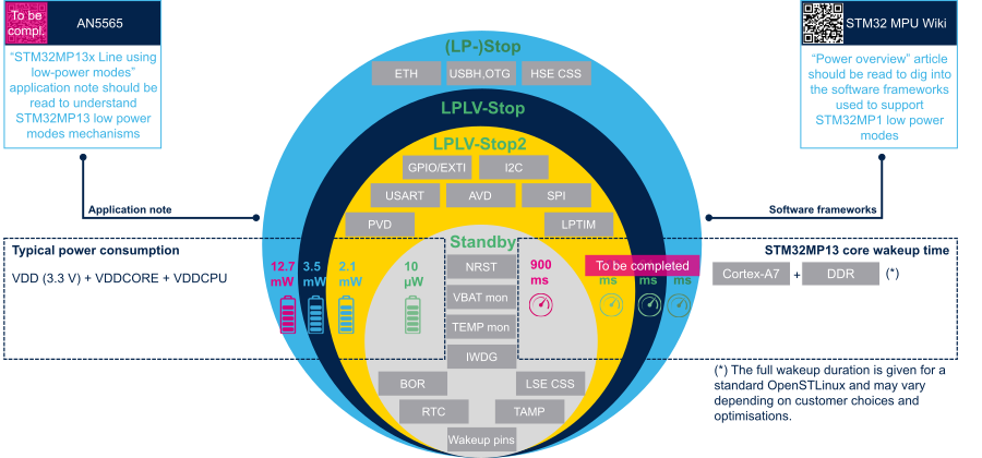
Refer to the AN5565 document for a deeper explanation of the low-power mode characteristics and dynamics.
Refer to the STM32MP1 power overview to discover the corresponding software architecture that enable using those modes with OpenSTLinux.
See STM32MP13 Datasheet and AN5787-STM32MP13x product lines system power consumption for details on consumption and wakeup time from low-power modes.
4.3.2. STM32MP13 wake-up time interpretation[edit | edit source]
- For Arm® Cortex®-A7 core:
- The wake-up times given in the above figure correspond to a typical OpenSTLinux distribution (around 7-Mbyte uImage, 600-Mbyte Weston rootfs, 35-second cold boot time)
5. On STM32MP15x lines [edit | edit source]
5.1. STM32MP15 power supplies[edit | edit source]
It is important to understand the perimeter of the two STM32MP15 main power supplies:
- VDD supplies I/Os and analog components such as reset, power management, oscillators and PLLs. VDD is present as far as the STM32MP15 is not in Off or VBAT mode. For a given system, VDD voltage is fixed and usually chosen between 1.8 V to 3.3 V typical.
- VDDCORE supplies the digital core domain and must be present after VDD at start up. Depending on the system low-power mode, VDDCORE voltage varies between switched off (0 V), the retention voltage (0.9 V) and the nominal voltage (1.2 V). The mapping of these voltage levels to the low-power modes is shown in the next paragraph.
For more information, refer to the PWR chapter of the STM32MP15 Reference Manual and to the STM32MP15 Datasheet.
5.2. STM32MP15 low-power modes[edit | edit source]
Starting from the Run mode, various actions can be taken to reduce the processor power consumption when all tasks have been completed:
- Stop the high-speed clock sources (PLLs/HSI/HSE/CSI): this corresponds to the Stop mode where the VDDCORE external regulator is kept at its nominal voltage. The regulator can even be switched in low-power mode in order to reduce its power consumption: this is the LP-Stop mode.
- Stop the high-speed clock sources (PLLs/HSI/HSE/CSI) and reduce VDDCORE voltage to its retention value: this is the LPLV-Stop mode, that enables to consume the minimum power while maintaining the content of all the registers and internal memories.
- Stop the high-speed clock sources (PLLs/HSI/HSE/CSI) and switch off VDDCORE: this is the Standby mode, where the content of all registers and internal memories is lost, apart from the ones that are in VSW domain that is supplied by VDD (when present) or VBAT (in VBAT mode). In particular, notice that the Backup registers, the BKPSRAM and the RETAM are in the VSW domain. Please also note that PWR and RCC both have some registers in the VSW (kept during Standby) and VDD (lost during Standby) domains.
One or several wake-up source(s) are used to exit from the above low-power modes and come back to Run mode. Not all internal peripherals are able to wake up from low-power modes. Table Functionalities depending on system operating mode located in the PWR chapter of the STM32MP15 Reference Manual, shows the wake-up capability of each peripheral. This is summarized in the figure in the following paragraph.
When the processor is put in one of these low-power modes, the external RAM (DDR) is usually put in Self-Refresh mode in order to keep its content whereas most of the STM32MP15 is no more active (no more clock generated for the DDR, no more Auto-refresh commands). This extra power consumption has to be considered at system level and depends on the selected DDR memory (refer to your memory provider datasheet).
The main side effect of using low-power modes is the wake-up time required to restore the system to a full running state (Run mode): the deepest you slept and the longest it needs to wake up. The next chapter illustrates this in order to allow you to make the best choice for your product.
5.3. STM32MP15 low-power strategy[edit | edit source]
5.3.1. Overview[edit | edit source]
The figure below shows, for each low-power mode:
- The peripherals that can be used as wake-up sources (grey boxes)
- The STM32MP15 typical power consumption (on the left)
- The system wake-up times in various configurations (on the right)
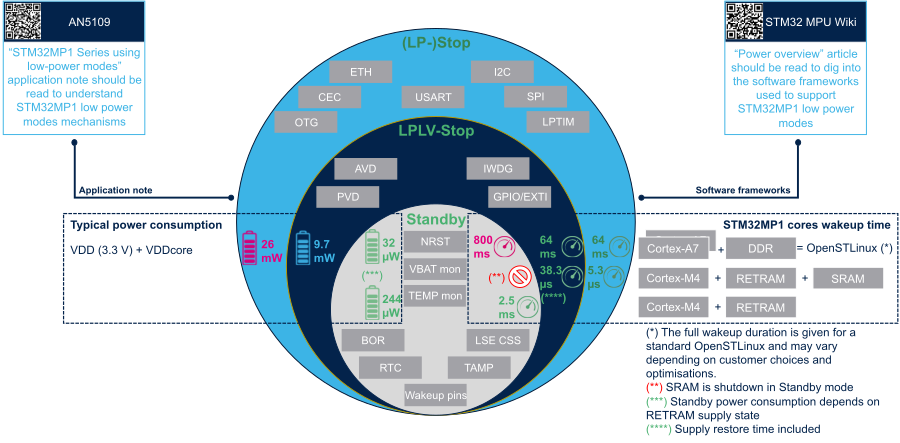
Refer to the AN5109 document for a deeper explanation of the low-power mode characteristics and dynamics.
Refer to the STM32MP1 power overview to discover the corresponding software architecture that enable using those modes with OpenSTLinux.
See STM32MP15 Datasheet and AN5284 - STM32MP1 series system power consumption for details on consumption and wakeup time from low-power modes.
5.3.2. STM32MP15 wake-up time interpretation[edit | edit source]
- For Arm® Cortex®-A7 core:
- The wake-up times given in the above figure correspond to a typical OpenSTLinux distribution (around 7-Mbyte uImage, 600-Mbyte Weston rootfs, 30-second cold boot time)
- For the Arm® Cortex®-M4 core:
- The wake-up times correspond to the return to the software execution, so your application extra time has to be added to those figures, which are taken from the STM32MP15 datasheets.
- The RETRAM and SRAM remain supplied in (LP-)Stop and LPLV-Stop modes, so the Cortex-M4 firmware code and data can use them.
- The RETRAM remains supplied in Standby mode, and can hence be used to store the code of a size limited firmware that would be executed at wake-up. Once woken up, the firmware can use again the SRAM for data storing and the application running on the Cortex-A7 core could even reload some services (code) in SRAM.
The core that is started on wake up from Standby is selected thanks to the MPU_BEN (Cortex-A7) and MCU_BEN (Cortex-M4) bits in RCC_MP_BOOTCR.
|
6. On STM32MP2 series[edit | edit source]
6.1. STM32MP2 power supplies[edit | edit source]
It is important to understand the perimeter of the STM32MP2 series main power supplies:
- VDD supplies the I/Os and the VDD domain and VDDA18AON supplies the system analog such as reset, power management, oscillators and OTP. VDD and VDDA18AON are present as far as the STM32MP23/STM32MP25 is not in Off or VBAT mode. For a given system, VDD voltage is fixed and usually chosen between 1.8 V to 3.3 V typical.
- VDDCORE supplies the digital core domain, except the Arm® Cortex®-A35 CPU, and must be present after VDD at start up. Depending on the system low-power mode, VDDCORE voltage varies between switched off (0 V), the retention voltage (0.67 V) and the nominal voltage (0.82 V). The mapping of these voltage levels to the low-power modes is shown in the next paragraph.
- VDDCPU supplies the Arm® Cortex®-A35 CPU, and must be present after VDD at start up. There is no precedence constraint between this supply and VDDCORE. Depending on the system low-power mode, VDDCPU voltage varies between switched off (0 V), the retention voltage (0.67 V), the nominal voltage (0.8 V) and the overdrive voltage (0.9 V). The mapping of these voltage levels to the low-power modes is shown in the next paragraph.
- VDDGPU supplies the GPU domain supply (only for STM32MP23x/STM32MP25x, not supported for STM32MP21x). Depending on the GPU mode, VDDGPU voltage varies between switched off (0 V), the retention voltage (0.67 V) and the nominal voltage (0.8 V) and the overdrive voltage (0.9 V).
- VDDIOx supplies the independent I/Os domain 1 to 4 for STM32MP23x/STM32MP25x, 1 to 3 for STM32MP21x
For more information, refer to the PWR chapter of the STM32 MPU documentations:
- STM32MP21 Reference Manual and STM32MP21 Datasheet
- STM32MP23 Reference Manual and STM32MP23 Datasheet
- STM32MP25 Reference Manual and STM32MP25 Datasheet
6.2. STM32MP2 low-power modes[edit | edit source]
Various actions can be taken to reduce the STM32MP2 series power consumption.
In Run1 mode, the user can:
- slow down system clocks and limit VDDCPU at their nominal voltages (no more overdrive),
- Switch off the clocks and supplies when the associated devices are not used. For example VDDGPU is switched off when GPU is stopped for STM32MP23x/STM32MP25x, or VDD33USB is switched off when USB PHY is not used.
Starting from the Run1 mode, you can select a low-mode mode when all tasks have been completed and CPU1 do not need to execute code (when waiting for an external event):
- Stop the CPU1 = Cortex A35 and VDDCPU external regulator, the Cortex-M33 and system D2 domain is still powered: this is Run2.
- Stop the system clock (including any PLL, and the system bus matrix clocks): this corresponds to the Stop1 mode where the VDDCORE and VDDCPU external regulators are kept at their nominal voltages.
The external regulators are allowed (through PWR_LP pins) to enter in low-power mode to reduce their power consumption: this is the LP-Stop1 mode. - Stop the system clock and reduce VDDCORE and VDDCPU voltages to their retention values: this is the LPLV-Stop1 mode, that enables to consume low power while maintaining the content of all the registers and internal memories, including the CPU1 sub-system.
- Stop the system clock and switch off VDDCPU: this is the Stop2 mode.
The external regulators are allowed (through PWR_LP pins) to enter in low-power mode to reduce their power consumption: this is the LP-Stop2 mode. - Stop the system clock, switch off VDDCPU and reduce VDDCORE voltages to their retention values: this is the LPLV-Stop2 mode, that enables to consume the minimum power while maintaining the content of all the registers and internal memories, except the CPU sub-system ones.
- Stop the system clock and switch off VDDCORE and VDDCPU: the content of all registers and internal memories is lost, apart from the ones that are in VSW domain that is supplied by:
- VDD when present, this is the Standby modes:
- for STM32MP21x, Standby mode
- for STM32MP23x/STM32MP25x, Standby1 mode when D3 domain is preserved or Standby2 mode (without D3 domain, the EXTI2 wake-up sources are not supported),
- VBAT when VDD is switched off, this is the VBAT modes:
- for STM32MP21x: VBAT,
- for STM32MP23x/STM32MP25x: VBAT1 with D3 domain or VBAT2.
- VDD when present, this is the Standby modes:
One or several wake-up source(s) are used to exit from the above low-power modes and come back to Run1 mode. Not all internal peripherals are able to wake up from low-power modes. The Table Functionalities depending on system operating mode located in the PWR chapter of the Reference Manual shows the wake-up capability of each peripheral (Table 91 for STM32MP21x or Table 94. for STM32MP23x/STM32MP25x)). For STM32MP23x/STM32MP25x, the D3 domain, containing the Backup registers, the BKPSRAM, some peripherals, the Cortex-M0+ (CPU3) only for STM32MP25x and a small part of the system control (including the EXTI2 and some registers of PWR and RCC), are in the VSW domain and is still supplied by VDDCORE or an internal backup regulator powered by VBAT. So their contents are kept, even if the D3 domain is in Standby mode (D3 domain is in power down) in Standby2 and VBAT2 modes.
When the processor is put in one of these low-power modes, the DDR controller put the external RAM (DDR) in Self-Refresh mode (no more clock generated for the DDR, no more Auto-refresh commands) in order to keep its content whereas most of the STM32 MPU is no more active and the Cortex-M33 firmware cannot be executed in DDR but only in STM32MP2 SRAM internal memory. The DDR power consumption in Self-Refresh mode has to be considered and depends on the selected DDR memory (refer to your memory provider datasheet).
For power off request, the Standby(STM32MP21x)/Standby2(STM32MP23x/STM32MP25x) mode or the VBAT modes can be used to keep the VSW domain, for example to preserve content of BKPSRAM and backup registers, but the supplies associated to DDR are switched off and DDR content is lost.
The low-power mode of external regulators requested through PWR_LP pins must be defined. This signal is used to request a regulator or a peripheral to enter low-voltage and/or low-power state. For example, you can deactivate the VTT_DRR supply with PWRCTRL1 pins of STPMIC25.
The main side effect of using low-power modes is the wake-up time required to restore the system to a full running state (Run1 mode): the deepest you slept and the longest it needs to wake up.
OpenSTLinux don't support all these modes, for example Run2 is not supported when the Cortex M33 firmware is running in DDR and for the boot on CPU1 = Cortex A35 the "legacy mode" is used (on Standby1 wake up only CPU1 boots, CPU2 is kept in hold); see STM32MP2 power overview for supported modes.
6.3. STM32MP2 low-power strategy[edit | edit source]
The wake-up adds constraints on the low power modes (see STM32MP2 power overview page for more details on wake-up groups) :
| Wake-Up | VDDCORE | System low-power mode VDDCPU |
Wake-up time |
|||
|---|---|---|---|---|---|---|
| WKUP pins RTC TAMPER monitoring IWDGx |
PVD PVM GPIOs |
Other EXTI Wake-Up: HPDMA, USB, UCPD1, ETH, USART, I2C, I3C, SPI, DTS, LPTIMx |
ON | OFF | ||
| X | X | X | ON | Run1 | Run2 | - |
| X | X | X | Stop1 | Stop2 | Low | |
| X | X | X | LP-Stop1 | LP-Stop2 | Low | |
| X | X | ON (reduced) | LPLV-Stop1[OSTL 1] | LPLV-Stop2 | Medium | |
| X | OFF | Standby | High | |||
The needed latency gives constraints on the required low power modes and also on the power consumption: the deepest low power mode, increase the wake-up time.
See STM32 MPU Datasheet and AN5730 - Guidelines for measuring system power consumption on STM32MP2 MPUs for details on consumption and wakeup time from low-power modes.
In OpenSTLinux, the low power sequence is performed at several level:
- Linux: the PM framework, including the userland, frameworks and drivers up to PSCI request
- LowPower: firmware which execute the suspend PSCI requests, it is composed by:
- for A35-TD flavor
 : TF-A BL31 (for PWR configuration and DDR self-refresh configuration) and OP-TEE, including the PMIC configuration
 - for M33-TD flavor : TF-A BL31 and OP-TEE for Cortex-A35 side; TF-M (including the PMIC configuration) and STM32MP2 low power firmware (PWR configuration and DDR self-refresh configuration) for Cortex-M33 side
- for A35-TD flavor
- HW: STM32MPU peripherals, including PWR and RCC with associated delay for pins PWR_CPU_ON, PWR_ON, PWR_LP, RCC NRSTC1MS, and including ROM code execution time for wake-up, including re-load time of FSBL-A for Standby exit.
The overall interruption latency is given the maximum duration of uninterruptible part of each software sequence, when wake-up interruption can't be handled without finish the suspend sequence, and of the uninterruptible part of the hardware sequence.
For OpenSTLinux, the M33-TD flavor ![]() reduces the interruption latency for Cortex-M33, but it will increase the overall latency for Linux interruption as the Cortex-A35 wake-up occurs only after Cortex-M33 (exit of DDR self refresh mode and SCMI server ready).
reduces the interruption latency for Cortex-M33, but it will increase the overall latency for Linux interruption as the Cortex-A35 wake-up occurs only after Cortex-M33 (exit of DDR self refresh mode and SCMI server ready).

For reference only the next table gives the available consumption values on STMicroelectronics boards and the some measured SW latencies with OpenSTlinux running in DDR for A35-TD flavor ![]()
- entry: measured time between PSCI OSI CpuIdle in Linux, so after Linux system suspend framework and without the suspend duration of each Linux driver, and BL31 WFI, so with OP-TEE suspend phasis.
- exit: measured time after WFI in TF-A and Linux return to CPUidle, before the Linux resume framework but including the OP-TEE resume
We indicate also for information the Linux PSCI OSI configuration defined in OpenSTLinux in SoC device tree (stm32mp251.dtsi and stm32mp211.dtsi ); they are used by the Linux CpuIdle governor to decide with scheduling information, expected time of the next wake-up, when the low power mode are useful:
- (entry-latency): Worst case latency in microseconds required to enter the idle state.
- (exit-latency): Worst case latency in microseconds required to exit the idle state. The exit-latency-us duration may be guaranteed only after entry-latency-us has passed.
- (min residency): Minimum residency duration in microseconds, inclusive of preparation and entry, for this idle state to be considered worthwhile energy wise
These measurements are not done for all the boards and all the modes; the available information are:
- on STM32MP257F-EV1 board with OpenSTLinux running in DDR4
| System mode | VDDCPU | VDDCORE | Latency | Power value (mW) | |||||||
|---|---|---|---|---|---|---|---|---|---|---|---|
| Entry (us) (entry-latency) |
Exit (us) (exit-latency) |
Total (us) (min residency) |
CPU | CORE (0.8V) |
IO (3.3V) |
DDR (1.2V) |
1V8 | Total | |||
| Run1 CSleep CRun@1.2GHz,0.8V CRun@1.5GHz0.9V |
ON | ON | - | 14 83 145 |
289 294 294 |
30 30 30 |
196 197 198 |
113 115 115 |
642 719 782 | ||
| Stop1 | 176 (300) |
80 (500) |
(1500) | ||||||||
| LP-Stop1 | (350) | (600) | (2000) | ||||||||
| LPLV-Stop1 | LOW | (350) | (2000) | (2500) | |||||||
| Run2 | OFF | ON | 0 | ||||||||
| Stop2 | 0 | ||||||||||
| LP-Stop2 | 0 | 12 | 12 | 12 | 20.5 | 56 | |||||
| LPLV-Stop2 | LOW | 0 | |||||||||
| Standby1 | OFF | 0 | 0 | 18 | 12 | 0 | 30 | ||||
| Standby2 DDR OFF (poweroff) |
OFF | - | 0 | 0 | 18 | 0 | 0 | 18 | |||
- STM32MP21 ST internal board with OpenSTLinux running in DDR4
| System mode | VDDCPU | VDDCORE | Latency | Power value (mW) | |||||||
|---|---|---|---|---|---|---|---|---|---|---|---|
| Entry (us) (entry-latency) |
Exit (us) (exit-latency) |
Total (us) (min residency) |
CPU | CORE | DDR | 1V8 | IO | Total | |||
| Run1 memtester cpuburn |
ON | ON | - | 141 165 |
238 208 |
346 198 |
63 63 |
211 211 |
999 846 | ||
| Stop1 | (300) | (500) | (1500) | ||||||||
| LP-Stop1 | (350) | (600) | (2000) | 1 | 5 | 16 | 17 | 48 | 87 | ||
| Run2 | OFF | ON | 0 | ||||||||
| Stop2 | 0 | ||||||||||
| LP-Stop2 | 0 | 5 | 16 | 17 | 48 | 86 | |||||
| LPLV-Stop2 | LOW | 0 | |||||||||
| Standby | OFF | - | 0 | 0 | 14 | 0 | 51 | 65 | |||
6.4. How to go further for STM32MP2[edit | edit source]
See STM32 MPU Datasheet and AN5730 for details.
Refer to the STM32MP2 power overview to discover the corresponding software architecture that enables using those modes with OpenSTLinux.
Refer to How to choose the STM32MP2 boot flavor to select CPUx to boot first.
Refer to the AN5726 document for a deeper explanation of the low-power mode characteristics and wake-up sources and typical power consumption.
Refer to the AN5729 document for impact on life time usage of power supply voltages.
7. References[edit | edit source]
- ↑ STPMIC description in www.st.com: https://www.st.com/en/power-management/multi-output-controllers-and-regulators.html
- ↑ SMPS: Switched Mode Power Supply, DC/DC buck converter (step-down)
- ↑ STPMIC1: https://www.st.com/en/power-management/stpmic1.html
- ↑ Boost: step-up DC/DC converter with a bypass
- ↑ STPMIC1L: https://www.st.com/en/power-management/stpmic1l.html
- ↑ STPMIC25: https://www.st.com/en/power-management/stpmic25.html
- ↑ STPMIC2L: https://www.st.com/en/power-management/stpmic2l.html
Arm® is a registered trademark of Arm Limited (or its subsidiaries) in the US and/or elsewhere. ![]()
Arm® is a registered trademark of Arm Limited (or its subsidiaries) in the US and/or elsewhere. ![]()