1. Article purpose[edit | edit source]
This article explains how to configure the SAI internal peripheral when it is assigned to the Linux® OS. In that case, it is controlled by the ALSA framework.
The configuration is performed using the device tree mechanism that provides a hardware description of the SAI peripheral, used by the SAI linux driver.
If the peripheral is assigned to another execution context, refer to How to assign an internal peripheral to an execution context article for guidelines on peripheral assignment and configuration.
2. DT bindings documentation[edit | edit source]
STM32 SAI device tree bindings [1] document describes all the required and optional configuration properties.
3. DT configuration[edit | edit source]
This hardware description is a combination of the STM32 microprocessor device tree files (.dtsi extension) and board device tree files (.dts extension). See the Device tree for an explanation of the device tree file split.
The SAI is used as a component of a sound card through Linux® kernel ALSA framework. The device tree nodes related to the sound card are described in board device tree.
The STM32CubeMX can be used to generate the board device tree. Refer to How to configure the DT using STM32CubeMX for more details.
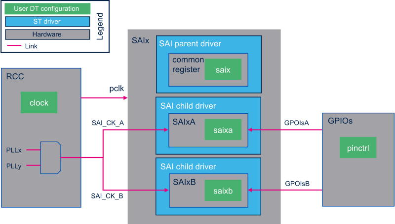
The STM32 SAI peripheral includes two independent audio subblocks that share common resources. The SAI device tree nodes reflects this architecture, as shown in the SAI DT samples below.
3.1. SAI clocks configuration[edit | edit source]
| The parent clock of the SAI kernel clock may not be exactly a multiple of the audio stream rate. A debug trace can be enabled in the SAI Linux driver, to report the clock rate accuracy. A deviation of 1000 ppm, on the audio stream frequency, might be considered acceptable for most people. |
3.1.1. On STM32MP1 series[edit | edit source]
Two parent clocks referred as "x8k" and "x11k", have to be declared for the SAI kernel clock:
- The "x8k" clock must be a multiple of 8kHz
- The "x11k" clock must be a multiple of 11.025kHz
Depending on the audio stream sampling rate, the SAI driver selects at runtime the relevant parent clock.
&saix {
	/* SAIx parent node. Configure common ressources  */
	clock-names = "pclk", "x8k", "x11k"; /* Peripheral and parent clocks configuration.  */
	...

	saixa {
		/* child node. Configure ressources dedicated to SAIxA subblock */
		clock-names = "sai_ck"; /* SAIxA kernel clock confguration.  */
		pinctrl-names = "default"; /* GPIOsA configuration.  */
		...
	};

	saixb {
		/* child node. Configure ressources dedicated to SAIxB subblock */
		clock-names = "sai_ck"; /* SAIxB kernel clock confguration.  */
		pinctrl-names = "default"; /* GPIOsB configuration.  */
		...
	};
};
3.1.2. On STM32MP2 series[edit | edit source]
The SAI kernel clock uses a single parent clock. At run-time, the SAI driver configures the rate of this parent clock, to the highest multiple frequency of the audio stream sampling rate.
&saix {
	/* SAIx parent node. Configure common ressources  */
	clock-names = "pclk"; /* Peripheral clock configuration.  */
	...

	saixa {
		/* child node. Configure ressources dedicated to SAIxA subblock */
		clock-names = "sai_ck"; /* SAIxA kernel clock confguration.  */
		pinctrl-names = "default"; /* GPIOsA configuration.  */
		...
	};

	saixb {
		/* child node. Configure ressources dedicated to SAIxB subblock */
		clock-names = "sai_ck"; /* SAIxB kernel clock confguration.  */
		pinctrl-names = "default"; /* GPIOsB configuration.  */
		...
	};
};
3.2. DT configuration (STM32 level)[edit | edit source]
The SAI nodes are declared in STM32 microprocessor device tree. They describe hardware parameters such as registers address, interrupt and DMA. This set of properties may not vary for a given STM32MPU.
On STM32MP13x lines ![]() , the SAI nodes are declared in stm32mp131.dtsi[2].
, the SAI nodes are declared in stm32mp131.dtsi[2].
On STM32MP15x lines ![]() , the SAI nodes are declared in stm32mp151.dtsi[3].
, the SAI nodes are declared in stm32mp151.dtsi[3].
On STM32MP21x lines ![]() , the SAI nodes are declared in stm32mp211.dtsi[4].
, the SAI nodes are declared in stm32mp211.dtsi[4].
On STM32MP23x lines ![]() , the SAI nodes are declared in stm32mp231.dtsi[5].
, the SAI nodes are declared in stm32mp231.dtsi[5].
On STM32MP25x lines ![]() , the SAI nodes are declared in stm32mp251.dtsi[6].
, the SAI nodes are declared in stm32mp251.dtsi[6].
3.3. DT configuration (board level)[edit | edit source]
The SAI configuration is board dependent, whether is it connected or not to an external component such as an audio codec. The links between the SAI and the other components define a soundcard. This soundcard has to be configured in the board device tree. Refer to soundcard configuration for examples of SAI configuration on various STM32MPU boards.
3.4. DT configuration examples[edit | edit source]
This chapter describes in details advanced SAI configurations. These examples are based on STM32MP1 boards SAI use cases. The corresponding device trees can be found in soundcard article.
| In this chapter, "SAI" stands for an SAI subblock, SAIxA or SAIxB. |
3.4.1. Setting SAI as a master clock provider[edit | edit source]
The SAI peripheral can provide a clock to an external component (such as a codec) through the mclk output pin. In this case, it acts as master clock (mclk) provider. The below DT sample gives an example of SAI configuration as mclk provider.
In this example the codec driver supports mclk input based on ASoC DAPM mechanism. If this is not the case, the codec driver has to be adapted. This can be achieved by adding a DAPM clock supply widget to the codec driver. An example of the required DAPM clock supply widget can be found in Cirrus CS42L51 codec source code[7]. In the below device tree example, the codec DAPM clock widget is named "MCLKX".
To allow mclk activation/deactivation, a DAPM route must be defined in the DT. This route is defined in the sound node, as shown below.
soundcard {
	routing =
		"Playback" , "MCLKX", /* Set a route between "MCLKX" and "playback" widgets */
		"Capture" , "MCLKX";
	...
};

codec: {
	clocks = <&sai2a>;     /* The codec is a consumer of SAI2A master clock */
	clock-names = "MCLKX"; /* Feed MCLKX codec clock with SAI2A master clock provider */
	...
};

&sai2 {
	...

	sai2a: audio-controller@4400b004 {
		#clock-cells = <0>; /* Set SAI2A as master clock provider */
		...
		sai2a_endpoint: endpoint {
			mclk-fs = <256>; /* Set mclk/fs ratio. (256 or 512) */
		};
	};
};
3.4.2. Sharing master clock between two SAIs[edit | edit source]
When an SAI is set as a master clock provider, another SAI can share this master clock. This can be achieved by setting the SAI as a mclk consumer through DT configuration. This means that the mclk consumer SAI can request to change the mclk rate, according to its own audio stream sampling rate. This implies that audio sampling rates must be identical when both SAI subblocks are used.
&sai2 {
	...

	sai2a: audio-controller@4400b004 {
		#clock-cells = <0>; /* Set SAI2A as master clock provider */
		...
	};

	sai2b: audio-controller@4400b024 {
		clocks = <&rcc SAI2_K>, <&sai2a>; /* SAI2B is a consumer of SAI2A master clock */
		clock-names = "sai_ck", "MCLK";   /* Feed SAI2B MCLK clock with SAI2A master clock provider */
		...
		sai2b_endpoint: endpoint {
			mclk-fs = <256>; /* Set mclk/fs ratio. (256 or 512) */
		};
	};
};
3.4.3. Sharing the codec interface between two SAIs[edit | edit source]
Two SAIs can be connected to the same codec interface, by sharing the I2S bus (i.e. FS and SCK clocks).
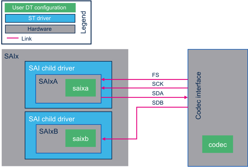
In such case:
- The codec has to be master on the I2S bus.
- Only one SAI is connected to the bus clocks. The other SAI has to be configured as a slave of the SAI connected to the bus.
- The I2S bus I/O pins must be managed at parent level, so that the corresponding pins are activated whatever the running SAI.
From ASoC point of view:
Two CPU DAIs have to be connected to the same codec DAI. Such topology is not supported natively by the ASoC audio graph card. Indeed, when the audio graph card parses the codec nodes, it expects to find DAI interface indexes, matching the endpoints indexes. A workaround consists in implementing the of_xlate_dai_id callback in the codec driver, to allow using the same DAI interface for both endpoints. An example of code can be found below or in the Cirrus CS42L51 codec source code[7].
- Code example
static int codec_of_xlate_dai_id(struct snd_soc_component *component,
				   struct device_node *endpoint)
{
	/* return dai id 0, whatever the endpoint index */
	return 0;
}
- DT example
codec {
	...
	codec_port {
		codec_tx_endpoint {
			remote-endpoint = <&sai2a_endpoint>;
			frame-master;    /* Set codec as master of SAI2A for FS clock. */
			bitclock-master; /* Set codec as master of SAI2A for SCK clock. */
		};

		codec_rx_endpoint { /* Second endpoint mapped on codec DAI 0 via of_xlate */
			remote-endpoint = <&sai2b_endpoint>;
			frame-master;    /* Set codec as master of SAI2B for FS clock. */
			bitclock-master; /* Set codec as master of SAI2B for SCK clock. */
		};
	};
};

&sai2 {
	pinctrl-names = "default", "sleep"; /* Defines SAI2A/B GPIOs at parent level. */
	pinctrl-0 = <&sai2a_pins_a>, <&sai2b_pins_b>;
	pinctrl-1 = <&sai2a_sleep_pins_a>, <&sai2b_sleep_pins_b>;
	...

	sai2a: audio-controller@4400b004 {
		remote-endpoint = <&codec_tx_endpoint>;
		...
	};

	sai2b: audio-controller@4400b024 {
		remote-endpoint = <&codec_rx_endpoint>;
		st,sync = <&sai2a 2>; /* Set SAI2B as slave of SAI2A. */
	};
};
4. How to configure the DT using STM32CubeMX[edit | edit source]
The STM32CubeMX tool can be used to configure the STM32MPU device and get the corresponding platform configuration device tree files.
The STM32CubeMX may not support all the properties described in the above DT bindings documentation paragraph. If so, the tool inserts user sections in the generated device tree. These sections can then be edited to add some properties and they are preserved from one generation to another. Refer to STM32CubeMX user manual for further information.
5. References[edit | edit source]