1. Article purpose[edit | edit source]
The purpose of this article is to:
- briefly introduce the GPIO peripheral and its main features,
- indicate the peripheral instances assignment at boot time and their assignment at runtime (including whether instances can be allocated to secure contexts),
- list the software frameworks and drivers managing the peripheral,
- explain how to configure the peripheral.
2. Peripheral overview[edit | edit source]
The GPIO peripheral is used to configure the device IO ports, also called pins or pads.
On STM32MP13x lines ![]() , each GPIO instance controls 16 pins (for GPIOA to GPIOG), 15 pins (for GPIOH) or 8 pins (for GPIOI).
, each GPIO instance controls 16 pins (for GPIOA to GPIOG), 15 pins (for GPIOH) or 8 pins (for GPIOI).
On STM32MP15x lines ![]() , each GPIO instance controls 16 pins (for GPIOA to GPIOJ) or 8 pins (for GPIOK and GPIOZ).
, each GPIO instance controls 16 pins (for GPIOA to GPIOJ) or 8 pins (for GPIOK and GPIOZ).
On STM32MP25x lines ![]() , each GPIO instance controls 16 pins (for GPIOA/B/D/E/F/G/I/J), 14 pins (for GPIOC), 12 pins (for GPIOH), 10 pins (for GPIOZ) or 8 pins (for GPIOK).
, each GPIO instance controls 16 pins (for GPIOA/B/D/E/F/G/I/J), 14 pins (for GPIOC), 12 pins (for GPIOH), 10 pins (for GPIOZ) or 8 pins (for GPIOK).
Every IO port implements the logic shown in the image below, taken from reference manual [1].
- The IO pin (on the right) is the physical connection to a chip external ball, soldered on the PCB. The link between each GPIO pin and each ball of the package is given in the datasheet [2].
- The Read and Write accesses allow the processor (Arm® Cortex®-A7 for STM32MP1 series or Arm® Cortex®-M4 for STM32MP15x lines
 ) to configure the peripheral, control the IO pin and get its status.
 - Alternate function (AF) links allow to connect the IO port to an internal peripheral digital line. In such a case, the IO direction is given by the line purpose: for instance, UART transmit line (TX) is an output.
- Analog links allow to connect the IO port to an internal peripheral analog line. In such a case, the IO direction is given by the line purpose: for instance, ADC input line is an input.
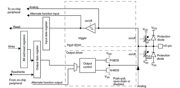
- Note:
- the pull-up and pull-down resistors are disabled (by hardware) in analog mode.
- at reset, all pins are set in analog input mode to protect the device and minimize the power consumption. All unused pins should be kept in this state.
The pin configuration done by the software consists in:
- setting the pin mode in the GPIOx_MODER register:
- input or output if the pin is used as general purpose (GPIO), controlled by software.
- analog.
- alternate function (AF).
- selecting the alternate function in the GPIOx_AFRH/L register (only when the pin mode is AF):
- each IO port can support up to 16 alternate functions that are documented in the datasheet [2].
- setting the pin characteristics:
- no pull-up and no pull-down or pull-up or pull-down in the GPIOx_PUPDR register, needs to be selected to be coherent with the hardware schematics.
- push-pull or open-drain in the GPIOx_OTYPER register, needs to be selected to be coherent with the hardware schematics.
- output speed in the GPIOx_OSPEEDR register needs to be tuned to achieve the expected level of performance (rising and falling times) while limiting electromagnetic interferences (EMI) and overconsumption. As example, the table below summarizes the maximum achievable frequency for each supported IO voltage and a 30pF load:
- On STM32MP13x lines :
- On STM32MP13x lines
GPIOx_OSPEEDR Meaning VDD=3v3 VDD=1v8
HSLV OFFVDD=1v8
HSLV ONb00 Low speed 21 MHz 5 MHz 23 MHz b01 Medium speed 44 MHz 15 MHz 44 MHz b10 High speed 100 MHz 37 MHz 90 MHz b11 Very high speed 166 MHz 50 MHz 133 MHz
- On STM32MP15x lines :
- On STM32MP15x lines
GPIOx_OSPEEDR Meaning VDD=3v3 VDD=1v8
HSLV OFFVDD=1v8
HSLV ONb00 Low speed 24 MHz 11 MHz 22 MHz b01 Medium speed 83 MHz 28 MHz 79 MHz b10 High speed 125 MHz 66 MHz 101 MHz b11 Very high speed 150 MHz 70 MHz 111 MHz
- On STM32MP25x lines :
- On STM32MP25x lines
GPIOx_OSPEEDR Meaning VDD=3v3 VDD=1v8
VRSEL OFFVDD=1v8
VRSEL ONb00 Low speed 45 MHz 20 MHz 45 MHz b01 Medium speed 70 MHz 25 MHz 70 MHz b10 High speed 100 MHz 30 MHz 100 MHz b11 Very high speed 120 MHz 45 MHz 120 MHz
- Notes:
- More information is available in the IO speed settings chapter of the "Getting started with..." [3].
- There are different IO types with different characteristics: for instance, all pads are not able to achieve 150 MHz while supplied at 3.3V. Refer to the datasheet [2] to get the characteristics for each pin.
- On STM32MP1 series, when supplied with VDD=1.8V, it is possible to enable the high speed low voltage (HSLV) pad mode for FTH (Five volt Tolerant High speed) and FTE (Five volt Tolerant Extended high speed) IO types on some peripherals via SYSCFG HSLVEN bits. Warning: As it could be destructive if used when VDD>2.7V, thanks to carefully read the HSLVEN bits documentation in reference manuals [1], especially the management of the OTP bit PRODUCT_BELOW_2V5 (STM32MP1 series) and lock mechanism (for STM32MP13x lines only).
- On STM32MP2 series, IOs could be configured either 1.8V or 3.3V compliance modes.
- In 1.8V mode, IOs are not 3.3V tolerant
- In 3.3V mode, IOs are not 5V tolerant
- By default, all IOs are in 3.3V mode, working in non-optimal condition when supplied with VDD=1.8V. It is responsibility of boot chain to configure IOs mode according to product configuration by setting PWR VRSEL bits for each IO domain.
- Warning: PWR VRSEL bits have effect only if associated HSLV OTP bit have been programmed.
- Warning: Enabling 1.8V mode when VDD=3.3V will damage IOs
The table below shows all possible characteristics combinations for each pin mode:
pin mode GPIOx_PUPDR GPIOx_OTYPER GPIOx_OSPEEDR analog
Not applicable Not applicable Not applicable input (GPIO or AF)
no pull-up and no pull-down
or pull-down
or pull-upNot applicable Not applicable output (GPIO or AF)
or bi-directional (AF)push-pull
or open-draincf. the table above
- Note:
- 'Not applicable' means that setting this register has no effect but, in any case, there is no risk for the device.
- On the other hand, leaving a register not initialized whereas it should be, may lead to an unpredictable behavior!
GPIO access configuration
- On STM32MP13x lines , any IOs from all GPIO banks can be unitary defined as secure or non-secure.
- On STM32MP15x lines , only IOs from GPIOZ can be unitary defined as secure or non-secure.
- On STM32MP25x lines , GPIO are RIF-aware, that means it is possible to assign each GPIO to one execution context define by:
- a security level
- a privilege level
- a CID
- For more information about RIF please refer to Resource Isolation Framework overview.
Refer to the STM32 MPU reference manuals [1] for the complete list of features, and to the software frameworks and drivers, introduced below, to see which features are implemented.
3. Peripheral usage[edit | edit source]
This chapter is applicable in the scope of the OpenSTLinux BSP running on the Arm® Cortex®-A processor(s), and the FwST-M Package running on the Arm® Cortex®-M processor.
3.1. Boot time assignment[edit | edit source]
The STM32CubeMX tool allows to configure in one place the GPIO configuration for boot time and runtime, so it is highly recommended to use it to generate your device tree. Moreover, STM32CubeMX integrates all the information documented in the datasheet [2], making this configuration step straightforward.
Since a GPIO configuration is done via atomic registers read and write, concurrent accesses from different cores must be avoided.
- On STM32MP15x lines all GPIO configurations are done by the Arm® Cortex®-A7.
- On STM32MP25x lines , GPIO configurations could be done by the different execution contexts as soon as RIF configuration has been applied by main processor (TDCID) secure OS.
The strategy is to progressively initialize the GPIO all along the boot chain, as soon as one boot component needs to use them:
- Most of the GPIOs used by the ROM code are directly defined in the ROM code but it is possible to change some pins muxing via dedicated words in BSEC.
- The other boot components are relying on a common binding[4] in the device tree to get the pins configuration:
- The FSBL configures both secure and non-secure pins according to peripherals firewall configuration.
- The Secure OS configures pins firewall protection and secure pins for secure peripherals
- The SSBL and Linux pinctrl only configure non-secure pins.
- On STM32MP15x lines , Linux also initializes the GPIO used by the Cortex-M4 coprocessor, via its resource manager.
- On STM32MP15x lines
3.1.1. On STM32MP13x lines [edit | edit source]
Click on ![]() to expand or collapse the legend...
to expand or collapse the legend...
Check boxes illustrate the possible peripheral allocations supported by the OpenSTLinux BSP:
- ⬚ means that the peripheral can be assigned to the given boot time context, but this configuration is not supported in OpenSTLinux BSP.
- ☐ means that the peripheral can be assigned to the given boot time context.
- ☑ means that the peripheral is assigned by default to the given boot time context and that the peripheral is mandatory for the OpenSTLinux BSP.
- ✓ is used for system peripherals that cannot be unchecked because they are hardware connected in the device.
The present chapter describes STMicroelectronics recommendations or choice of implementation. Additional possibilities might be described in STM32 MPU reference manuals.
| Domain | Peripheral | Boot time allocation | Comment | |||
|---|---|---|---|---|---|---|
| Instance | Cortex-A7 secure (ROM code) |
Cortex-A7 secure (TF-A BL2) |
Cortex-A7 nonsecure (U-Boot) | |||
| Core/IOs | GPIO | GPIOA-I | ✓ | ☑ | ☐ | The pins can individually be secured |
3.1.2. On STM32MP15x lines [edit | edit source]
Click on ![]() to expand or collapse the legend...
to expand or collapse the legend...
Check boxes illustrate the possible peripheral allocations supported by the OpenSTLinux BSP:
- ⬚ means that the peripheral can be assigned to the given boot time context, but this configuration is not supported in OpenSTLinux BSP.
- ☐ means that the peripheral can be assigned to the given boot time context.
- ☑ means that the peripheral is assigned by default to the given boot time context and that the peripheral is mandatory for the OpenSTLinux BSP.
- ✓ is used for system peripherals that cannot be unchecked because they are hardware connected in the device.
The present chapter describes STMicroelectronics recommendations or choice of implementation. Additional possibilities might be described in STM32 MPU reference manuals.
| Domain | Peripheral | Boot time allocation | Comment | |||
|---|---|---|---|---|---|---|
| Instance | Cortex-A7 secure (ROM code) |
Cortex-A7 secure (TF-A BL2) |
Cortex-A7 nonsecure (U-Boot) | |||
| Core/IOs | GPIO | GPIOA-K | ✓ | ☑ (*) | ☐ | The pins cannot be secured (*): despite they cannot be secured, the pins can be used by the secure context |
| GPIOZ | ☐ | ☐ | The pins can individually be secured | |||
3.1.1. On STM32MP21x lines [edit | edit source]
3.1.1.1. For A35-TD flavor  [edit | edit source]
Click on ![]() to expand or collapse the legend...
to expand or collapse the legend...
Check boxes illustrate the possible peripheral allocations supported by the OpenSTLinux BSP:
- ⬚ means that the peripheral can be assigned to the given boot time context, but this configuration is not supported in OpenSTLinux BSP.
- ☐ means that the peripheral can be assigned to the given boot time context.
- ☑ means that the peripheral is assigned by default to the given boot time context and that the peripheral is mandatory for the OpenSTLinux BSP.
- ✓ is used for system peripherals that cannot be unchecked because they are hardware connected in the device.
The present chapter describes STMicroelectronics recommendations or choice of implementation. Additional possibilities might be described in STM32 MPU reference manuals.
| Domain | Peripheral | Boot time allocation | Comment | |||
|---|---|---|---|---|---|---|
| Instance | Cortex-A35 secure (ROM code) |
Cortex-A35 secure (TF-A BL2) |
Cortex-A35 nonsecure (U-Boot) | |||
| Core/IOs | GPIO |
GPIOA-I | Shareable at internal peripheral level thanks to the RIF: see the boot time allocation per feature | |||
| GPIOZ | Shareable at internal peripheral level thanks to the RIF: see the boot time allocation per feature | |||||
The below table shows the possible boot time allocations for the features of the GPIOA-I instance.
| Feature | Boot time allocation |
Comment | ||
|---|---|---|---|---|
| Cortex-A35 secure (ROM code) |
Cortex-A35 secure (TF-A BL2) |
Cortex-A35 nonsecure (U-Boot) | ||
| GPIOA-I IOy | ✓ | ☐ | ☐ | |
The below table shows the possible boot time allocations for the features of the GPIOZ instance.
| Feature | Boot time allocation |
Comment | ||
|---|---|---|---|---|
| Cortex-A35 secure (ROM code) |
Cortex-A35 secure (TF-A BL2) |
Cortex-A35 nonsecure (U-Boot) | ||
| GPIOZ IOy | ☐ | ☐ | ||
3.1.1.2. For M33-TD flavor [edit | edit source]
Click on ![]() to expand or collapse the legend...
to expand or collapse the legend...
Check boxes illustrate the possible peripheral allocations supported by the OpenSTLinux BSP:
- ⬚ means that the peripheral can be assigned to the given boot time context, but this configuration is not supported in OpenSTLinux BSP.
- ☐ means that the peripheral can be assigned to the given boot time context.
- ☑ means that the peripheral is assigned by default to the given boot time context and that the peripheral is mandatory for the OpenSTLinux BSP.
- ✓ is used for system peripherals that cannot be unchecked because they are hardware connected in the device.
The present chapter describes STMicroelectronics recommendations or choice of implementation. Additional possibilities might be described in STM32 MPU reference manuals.
| Domain | Peripheral | Boot time allocation | Comment | ||||
|---|---|---|---|---|---|---|---|
| Instance | Cortex-A35 secure (ROM code) |
Cortex-A35 secure (TF-A BL2) |
Cortex-A35 nonsecure (U-Boot) |
Cortex-M33 secure (MCUboot) | |||
| Core/IOs | GPIO |
GPIOA-I | Shareable at internal peripheral level thanks to the RIF: see the boot time allocation per feature | ||||
| GPIOZ | Shareable at internal peripheral level thanks to the RIF: see the boot time allocation per feature | ||||||
The below table shows the possible boot time allocations for the features of the GPIOA-I instance.
| Feature | Boot time allocation |
Comment | |||
|---|---|---|---|---|---|
| Cortex-A35 secure (ROM code) |
Cortex-A35 secure (TF-A BL2) |
Cortex-A35 nonsecure (U-Boot) |
Cortex-M33 secure (MCUboot) | ||
| GPIOA-I IOy | ✓ | ☐ | ☐ | ☐ | |
The below table shows the possible boot time allocations for the features of the GPIOZ instance.
| Feature | Boot time allocation |
Comment | |||
|---|---|---|---|---|---|
| Cortex-A35 secure (ROM code) |
Cortex-A35 secure (TF-A BL2) |
Cortex-A35 nonsecure (U-Boot) |
Cortex-M33 secure (MCUboot) | ||
| GPIOZ IOy | ☐ | ☐ | ☐ | ||
3.1.2. On STM32MP23x lines and STM32MP25x lines [edit | edit source]
3.1.2.1. For A35-TD flavor [edit | edit source]
Click on ![]() to expand or collapse the legend...
to expand or collapse the legend...
Check boxes illustrate the possible peripheral allocations supported by the OpenSTLinux BSP:
- ⬚ means that the peripheral can be assigned to the given boot time context, but this configuration is not supported in OpenSTLinux BSP.
- ☐ means that the peripheral can be assigned to the given boot time context.
- ☑ means that the peripheral is assigned by default to the given boot time context and that the peripheral is mandatory for the OpenSTLinux BSP.
- ✓ is used for system peripherals that cannot be unchecked because they are hardware connected in the device.
The present chapter describes STMicroelectronics recommendations or choice of implementation. Additional possibilities might be described in STM32 MPU reference manuals.
| Domain | Peripheral | Boot time allocation | Comment | |||
|---|---|---|---|---|---|---|
| Instance | Cortex-A35 secure (ROM code) |
Cortex-A35 secure (TF-A BL2) |
Cortex-A35 nonsecure (U-Boot) | |||
| Core/IOs | GPIO |
GPIOA-K | Shareable at internal peripheral level thanks to the RIF: see the boot time allocation per feature | |||
| GPIOZ | Shareable at internal peripheral level thanks to the RIF: see the boot time allocation per feature | |||||
The below table shows the possible boot time allocations for the features of the GPIOA-K instance.
| Feature | Boot time allocation |
Comment | ||
|---|---|---|---|---|
| Cortex-A35 secure (ROM code) |
Cortex-A35 secure (TF-A BL2) |
Cortex-A35 nonsecure (U-Boot) | ||
| GPIOA-K IOy | ✓ | ☐ | ☐ | |
The below table shows the possible boot time allocations for the features of the GPIOZ instance.
| Feature | Boot time allocation |
Comment | ||
|---|---|---|---|---|
| Cortex-A35 secure (ROM code) |
Cortex-A35 secure (TF-A BL2) |
Cortex-A35 nonsecure (U-Boot) | ||
| GPIOZ IOy | ☐ | ☐ | ||
3.1.2.2. For M33-TD flavor [edit | edit source]
Click on ![]() to expand or collapse the legend...
to expand or collapse the legend...
Check boxes illustrate the possible peripheral allocations supported by the OpenSTLinux BSP:
- ⬚ means that the peripheral can be assigned to the given boot time context, but this configuration is not supported in OpenSTLinux BSP.
- ☐ means that the peripheral can be assigned to the given boot time context.
- ☑ means that the peripheral is assigned by default to the given boot time context and that the peripheral is mandatory for the OpenSTLinux BSP.
- ✓ is used for system peripherals that cannot be unchecked because they are hardware connected in the device.
The present chapter describes STMicroelectronics recommendations or choice of implementation. Additional possibilities might be described in STM32 MPU reference manuals.
| Domain | Peripheral | Boot time allocation | Comment | ||||
|---|---|---|---|---|---|---|---|
| Instance | Cortex-A35 secure (ROM code) |
Cortex-A35 secure (TF-A BL2) |
Cortex-A35 nonsecure (U-Boot) |
Cortex-M33 secure (MCUboot) | |||
| Core/IOs | GPIO |
GPIOA-K | Shareable at internal peripheral level thanks to the RIF: see the boot time allocation per feature | ||||
| GPIOZ | Shareable at internal peripheral level thanks to the RIF: see the boot time allocation per feature | ||||||
The below table shows the possible boot time allocations for the features of the GPIOA-K instance.
| Feature | Boot time allocation |
Comment | |||
|---|---|---|---|---|---|
| Cortex-A35 secure (ROM code) |
Cortex-A35 secure (TF-A BL2) |
Cortex-A35 nonsecure (U-Boot) |
Cortex-M33 secure (MCUboot) | ||
| GPIOA-K IOy | ✓ | ☐ | ☐ | ☐ | |
The below table shows the possible boot time allocations for the features of the GPIOZ instance.
| Feature | Boot time allocation |
Comment | |||
|---|---|---|---|---|---|
| Cortex-A35 secure (ROM code) |
Cortex-A35 secure (TF-A BL2) |
Cortex-A35 nonsecure (U-Boot) |
Cortex-M33 secure (MCUboot) | ||
| GPIOZ IOy | ☐ | ☐ | ☐ | ||
3.2. Runtime assignment[edit | edit source]
The GPIO configuration must not be done from different cores to avoid concurrent accesses, but this is not the case for the GPIO using: each core can manipulate IO on its own since dedicated set/clear registers are available for that.
Nevertheless, beyond the boot time, the GPIO configuration also evolves at runtime: while entering in low power mode, some GPIOs may be put back to analog input mode in order to reduce the power consumption.
On STM32MP1 series, this is done in two times:
- the Arm® Cortex®-A non-secure takes care of the non-secure pins with Linux IOs pins frameworks.
- the Arm® Cortex®-A secure takes care of the secure pins.
On wakeup, the boot chain restores the GPIO configuration similarly to what is done at boot time.
On STM32MP25x lines ![]() , thanks to the RIF, each SW component shall take care of its pins during low power entry and exit sequences.
, thanks to the RIF, each SW component shall take care of its pins during low power entry and exit sequences.
3.2.1. On STM32MP13x lines [edit | edit source]
Click on ![]() to expand or collapse the legend...
to expand or collapse the legend...
Check boxes illustrate the possible peripheral allocations supported by the OpenSTLinux BSP:
- ⬚ means that the peripheral can be assigned to the given runtime context, but this configuration is not supported in OpenSTLinux BSP.
- ☐ means that the peripheral can be assigned to the given runtime context.
- ☑ means that the peripheral is assigned by default to the given runtime context and that the peripheral is mandatory for the OpenSTLinux BSP.
- ✓ is used for system peripherals that cannot be unchecked because they are hardware connected in the device.
Refer to How to assign an internal peripheral to an execution context for more information on how to assign peripherals manually or via STM32CubeMX.
The present chapter describes STMicroelectronics recommendations or choice of implementation. Additional possibilities might be described in STM32MP13 reference manuals.
| Domain | Peripheral | Runtime allocation | Comment | ||
|---|---|---|---|---|---|
| Instance | Cortex-A7 secure (OP-TEE) |
Cortex-A7 nonsecure (Linux) | |||
| Core/IOs | GPIO | GPIOA-I | ☐ | ☐ | The pins can individually be secured |
3.2.2. On STM32MP15x lines [edit | edit source]
Click on ![]() to expand or collapse the legend...
to expand or collapse the legend...
Check boxes illustrate the possible peripheral allocations supported by the OpenSTLinux BSP:
- ⬚ means that the peripheral can be assigned to the given runtime context, but this configuration is not supported in OpenSTLinux BSP.
- ☐ means that the peripheral can be assigned to the given runtime context.
- ☑ means that the peripheral is assigned by default to the given runtime context and that the peripheral is mandatory for the OpenSTLinux BSP.
- ✓ is used for system peripherals that cannot be unchecked because they are hardware connected in the device.
Refer to How to assign an internal peripheral to an execution context for more information on how to assign peripherals manually or via STM32CubeMX.
The present chapter describes STMicroelectronics recommendations or choice of implementation. Additional possiblities might be described in STM32MP15 reference manuals.
| Domain | Peripheral | Runtime allocation | Comment | |||
|---|---|---|---|---|---|---|
| Instance | Cortex-A7 secure (OP-TEE) |
Cortex-A7 nonsecure (Linux) |
Cortex-M4 (STM32Cube) | |||
| Core/IOs | GPIO | GPIOA-K | ☐ (*) | ☐ | ☐ | The pins can individually be shared (*): despite they cannot be secured, the pins can be used by the secure context |
| GPIOZ | ☐ | ☐ | ☐ | The pins can individually be secured or shared | ||
3.2.1. On STM32MP21x lines [edit | edit source]
The tables below are applicable to any TD flavor (A35-TD or M33-TD) ![]() .
.
Click on ![]() to expand or collapse the legend...
to expand or collapse the legend...
Check boxes illustrate the possible peripheral allocations supported by the OpenSTLinux BSP:
- ⬚ means that the peripheral can be assigned to the given runtime context, but this configuration is not supported in OpenSTLinux BSP.
- ☐ means that the peripheral can be assigned to the given runtime context.
- ☑ means that the peripheral is assigned by default to the given runtime context and that the peripheral is mandatory for the OpenSTLinux BSP.
- ✓ is used for system peripherals that cannot be unchecked because they are hardware connected in the device.
Refer to How to assign an internal peripheral to an execution context for more information on how to assign peripherals manually or via STM32CubeMX.
The present chapter describes STMicroelectronics recommendations or choice of implementation. Additional possibilities might be described in STM32MP21 reference manuals.
| Domain | Peripheral | Runtime allocation | Comment | ||||
|---|---|---|---|---|---|---|---|
| Instance | Cortex-A35 secure (OP-TEE / TF-A BL31) |
Cortex-A35 nonsecure (Linux) |
Cortex-M33 secure (TF-M) |
Cortex-M33 nonsecure (STM32Cube) | |||
| Core/IOs | GPIO |
GPIOA-I | Shareable at internal peripheral level thanks to the RIF: see the runtime allocation per feature | ||||
| GPIOZ | Shareable at internal peripheral level thanks to the RIF: see the runtime allocation per feature | ||||||
The below table shows the possible runtime allocations for the features of the GPIOA-I instance.
| Feature | Runtime allocation |
Comment | |||
|---|---|---|---|---|---|
| Cortex-A35 secure (OP-TEE / TF-A BL31) |
Cortex-A35 nonsecure (Linux) |
Cortex-M33 secure (TF-M) |
Cortex-M33 nonsecure (STM32Cube) | ||
| GPIOA-I IOy | ☐OP-TEE ☐TF-A BL31 |
☐ | ☐ | ☐ | |
The below table shows the possible runtime allocations for the features of the GPIOZ instance.
| Feature | Runtime allocation |
Comment | |||
|---|---|---|---|---|---|
| Cortex-A35 secure (OP-TEE / TF-A BL31) |
Cortex-A35 nonsecure (Linux) |
Cortex-M33 secure (TF-M) |
Cortex-M33 nonsecure (STM32Cube) | ||
| GPIOZ IOy | ☐OP-TEE ☐TF-A BL31 |
☐ | ☐ | ☐ | |
3.2.2. On STM32MP23x lines [edit | edit source]
The tables below are applicable to any TD flavor (A35-TD or M33-TD) ![]() .
.
Click on ![]() to expand or collapse the legend...
to expand or collapse the legend...
Check boxes illustrate the possible peripheral allocations supported by the OpenSTLinux BSP:
- ⬚ means that the peripheral can be assigned to the given runtime context, but this configuration is not supported in OpenSTLinux BSP.
- ☐ means that the peripheral can be assigned to the given runtime context.
- ☑ means that the peripheral is assigned by default to the given runtime context and that the peripheral is mandatory for the OpenSTLinux BSP.
- ✓ is used for system peripherals that cannot be unchecked because they are hardware connected in the device.
Refer to How to assign an internal peripheral to an execution context for more information on how to assign peripherals manually or via STM32CubeMX.
The present chapter describes STMicroelectronics recommendations or choice of implementation. Additional possibilities might be described in STM32MP23 reference manuals.
| Domain | Peripheral | Runtime allocation | Comment | ||||
|---|---|---|---|---|---|---|---|
| Instance | Cortex-A35 secure (OP-TEE / TF-A BL31) |
Cortex-A35 nonsecure (Linux) |
Cortex-M33 secure (TF-M) |
Cortex-M33 nonsecure (STM32Cube) | |||
| Core/IOs | GPIO |
GPIOA-K | Shareable at internal peripheral level thanks to the RIF: see the runtime allocation per feature | ||||
| GPIOZ | Shareable at internal peripheral level thanks to the RIF: see the runtime allocation per feature | ||||||
The below table shows the possible runtime allocations for the features of the GPIOA-K instance.
| Feature | Runtime allocation |
Comment | |||
|---|---|---|---|---|---|
| Cortex-A35 secure (OP-TEE / TF-A BL31) |
Cortex-A35 nonsecure (Linux) |
Cortex-M33 secure (TF-M) |
Cortex-M33 nonsecure (STM32Cube) | ||
| GPIOA-K IOy | ☐OP-TEE ☐TF-A BL31 |
☐ | ☐ | ☐ | |
The below table shows the possible runtime allocations for the features of the GPIOZ instance.
| Feature | Runtime allocation |
Comment | |||
|---|---|---|---|---|---|
| Cortex-A35 secure (OP-TEE / TF-A BL31) |
Cortex-A35 nonsecure (Linux) |
Cortex-M33 secure (TF-M) |
Cortex-M33 nonsecure (STM32Cube) | ||
| GPIOZ IOy | ☐OP-TEE ☐TF-A BL31 |
☐ | ☐ | ☐ | |
3.2.3. On STM32MP25x lines [edit | edit source]
The tables below are applicable to any TD flavor (A35-TD or M33-TD) ![]() .
.
Click on ![]() to expand or collapse the legend...
to expand or collapse the legend...
Check boxes illustrate the possible peripheral allocations supported by the OpenSTLinux BSP:
- ⬚ means that the peripheral can be assigned to the given runtime context, but this configuration is not supported in OpenSTLinux BSP.
- ☐ means that the peripheral can be assigned to the given runtime context.
- ☑ means that the peripheral is assigned by default to the given runtime context and that the peripheral is mandatory for the OpenSTLinux BSP.
- ✓ is used for system peripherals that cannot be unchecked because they are hardware connected in the device.
Refer to How to assign an internal peripheral to an execution context for more information on how to assign peripherals manually or via STM32CubeMX.
The present chapter describes STMicroelectronics recommendations or choice of implementation. Additional possibilities might be described in STM32MP25 reference manuals.
| Domain | Peripheral | Runtime allocation | Comment | |||||
|---|---|---|---|---|---|---|---|---|
| Instance | Cortex-A35 secure (OP-TEE / TF-A BL31) |
Cortex-A35 nonsecure (Linux) |
Cortex-M33 secure (TF-M) |
Cortex-M33 nonsecure (STM32Cube) |
Cortex-M0+ (STM32Cube) | |||
| Core/IOs | GPIO |
GPIOA-K | Shareable at internal peripheral level thanks to the RIF: see the runtime allocation per feature | |||||
| GPIOZ | Shareable at internal peripheral level thanks to the RIF: see the runtime allocation per feature | |||||||
The below table shows the possible runtime allocations for the features of the GPIOA-K instance.
| Feature | Runtime allocation |
Comment | ||||
|---|---|---|---|---|---|---|
| Cortex-A35 secure (OP-TEE / TF-A BL31) |
Cortex-A35 nonsecure (Linux) |
Cortex-M33 secure (TF-M) |
Cortex-M33 nonsecure (STM32Cube) |
Cortex-M0+ (STM32Cube) | ||
| GPIOA-K IOy | ☐OP-TEE ☐TF-A BL31 |
☐ | ☐ | ☐ | - | |
The below table shows the possible runtime allocations for the features of the GPIOZ instance.
| Feature | Runtime allocation |
Comment | ||||
|---|---|---|---|---|---|---|
| Cortex-A35 secure (OP-TEE / TF-A BL31) |
Cortex-A35 nonsecure (Linux) |
Cortex-M33 secure (TF-M) |
Cortex-M33 nonsecure (STM32Cube) |
Cortex-M0+ (STM32Cube) | ||
| GPIOZ IOy | ☐OP-TEE ☐TF-A BL31 |
☐ | ☐ | ☐ | ☐ | |
4. Software frameworks and drivers[edit | edit source]
Below are listed the software frameworks and drivers managing the GPIO peripheral for the embedded software components listed in the above tables.
- Linux®: Linux IOs pins overview
- OP-TEE: GPIO OP-TEE driver and header file of GPIO OP-TEE driver
- STM32Cube: GPIO HAL driver and header file of GPIO HAL module
- TF-A BL2: GPIO driver and header file of GPIO driver
- U-Boot: GPIO driver and header file of GPIO driver
- TF-M: GPIO driver and header file of GPIO driver
5. How to assign and configure the peripheral[edit | edit source]
The peripheral assignment can be done via the STM32CubeMX graphical tool (and manually completed if needed).
This tool also helps to configure the peripheral:
- partial device trees (pin control and clock tree) generation for the OpenSTLinux software components,
- HAL initialization code generation for the STM32CubeMPU Package.
The configuration is applied by the firmware running in the context in which the peripheral is assigned.
In Linux kernel, each GPIO bank is declared as a "gpio-controller" in the device tree and each pin can then be used via two different consumer frameworks:
- Pinctrl framework is used to control the alternate function (AF) selection for a given device driver, via the Pinctrl device tree configuration.
- Gpiolib framework is used to control a pin in GPIO mode from another device driver or a user space application: refer to GPIO device tree configuration for further details.
6. References[edit | edit source]
Arm® is a registered trademark of Arm Limited (or its subsidiaries) in the US and/or elsewhere. ![]()
Arm® is a registered trademark of Arm Limited (or its subsidiaries) in the US and/or elsewhere. ![]()