1. Article purpose[edit | edit source]
This article explains how to configure the I2C internal peripheral[1] when the peripheral is assigned to Linux® OS, and in particular:
- how to configure the STM32 I2C peripheral
- how to configure the STM32 external I2C devices present either on the board or on a hardware extension.
The configuration is performed using the device tree mechanism[2].
It is used by the STM32 I2C Linux® driver that registers relevant information in the I2C framework.
If the peripheral is assigned to another execution context, refer to How to assign an internal peripheral to an execution context article for guidelines on peripheral assignment and configuration.
2. DT bindings documentation[edit | edit source]
The I2C is represented by:
3. DT configuration[edit | edit source]
This hardware description is a combination of the STM32 microprocessor device tree files (.dtsi extension) and board device tree files (.dts extension). See the Device tree for an explanation of the device tree file split.
STM32CubeMX can be used to generate the board device tree. Refer to How to configure the DT using STM32CubeMX for more details.
3.1. DT configuration (STM32 level)[edit | edit source]
At device level, the I2C controller is declared as follows:
- for STM32MP13x lines
 in stm32mp131.dtsi[5]
i2c1: i2c@40012000 {
       compatible = "st,stm32mp13-i2c";
       reg = <0x40012000 0x400>;
       interrupt-names = "event", "error";
       interrupts-extended = <&exti 21 IRQ_TYPE_LEVEL_HIGH>,
                             <&intc GIC_SPI 33 IRQ_TYPE_LEVEL_HIGH>;
       clocks = <&rcc I2C1_K>;
       resets = <&rcc I2C1_R>;
       #address-cells = <1>;
       #size-cells = <0>;
       dmas = <&dmamux1 33 0x400 0x01>,
              <&dmamux1 34 0x400 0x01>;
       dma-names = "rx", "tx";
       st,syscfg-fmp = <&syscfg 0x4 0x1>;
       i2c-analog-filter;
       power-domains = <&pd_core_ret>;
       wakeup-source;
       status = "disabled";
};
- for STM32MP15x lines in stm32mp151.dtsi[6]
i2c1: i2c@40012000 {
       compatible = "st,stm32mp15-i2c";
       reg = <0x40012000 0x400>;
       interrupt-names = "event", "error";
       interrupts-extended = <&exti 21 IRQ_TYPE_LEVEL_HIGH>,
                             <&intc GIC_SPI 32 IRQ_TYPE_LEVEL_HIGH>;
       clocks = <&rcc I2C1_K>;
       resets = <&rcc I2C1_R>;
       #address-cells = <1>;
       #size-cells = <0>;
       dmas = <&dmamux1 33 0x400 0x01>,
              <&dmamux1 34 0x400 0x01>;
       dma-names = "rx", "tx";
       power-domains = <&pd_core>;
       st,syscfg-fmp = <&syscfg 0x4 0x1>;
       wakeup-source;
       i2c-analog-filter;
       access-controllers = <&etzpc 34>;
       status = "disabled";
};
i2c1: i2c@40120000 {
       compatible = "st,stm32mp25-i2c";
       reg = <0x40120000 0x400>;
       interrupt-names = "event";
       interrupts = <GIC_SPI 108 IRQ_TYPE_LEVEL_HIGH>;
       clocks = <&rcc CK_KER_I2C1>;
       resets = <&rcc I2C1_R>;
       #address-cells = <1>;
       #size-cells = <0>;
       dmas = <&hpdma 27 0x20 0x00003012>,
              <&hpdma 28 0x20 0x00003021>;
       dma-names = "rx", "tx";
       access-controllers = <&rifsc 41>;
       power-domains = <&CLUSTER_PD>;
       status = "disabled";
};
3.2. DT configuration (board level)[edit | edit source]
&i2c2 {
	pinctrl-names = "default", "sleep";
	pinctrl-0 = <&i2c2_pins_a>;
	pinctrl-1 = <&i2c2_pins_sleep_a>;
	i2c-scl-rising-time-ns = <185>;
	i2c-scl-falling-time-ns = <20>;
        st,smbus-alert;
        smbus;
	status = "okay";
	/delete-property/dmas;
	/delete-property/dma-names;

	ov5640: camera@3c {
         [...]
	};
};
There are two levels of device tree configuration:
[edit | edit source]
The device tree properties related to the I²C internal peripheral and to the I²C bus which belong to i2cx node
- pinctrl-0&1 configuration depends on hardware board configuration and how the I2C devices are connected to SCL, SDA (and SMBA if device is SMBus Compliant) pins.
More details about pin configuration are available here: Pinctrl device tree configuration - clock-frequency represents the I2C bus speed : normal (100KHz), Fast (400KHz) and Fast+(up to 1MHz). This value is given in Hz.
- dmas By default, DMAs are enabled for all I2C instances. This is up to the user to remove them if not needed. /delete-property/ is used to remove DMA usage for I2C. Both /delete-property/dma-names and /delete-property/dmas have to be inserted to get rid of DMAs.
- i2c-scl-rising/falling-time-ns are optional values depending on the board hardware characteristics: wires length, resistor and capacitor of the hardware design.
These values must be provided in nanoseconds and can be measured by observing the SCL rising and falling slope on an oscilloscope. See how to measure I2C timings.
The I2C driver uses this information to compute accurate I2C timings according to the requested clock-frequency.
The STM32CubeMX implements an algorithm that follows the I2C standard and takes into account the user inputs.
When those values are not provided, the driver uses its default values.
Providing wrong parameters will produce inaccurate clock-frequency. In case the driver fails to compute timing parameters in line with the user input (SCL raising/falling and clock frequency), the clock frequency will be downgraded to a lower frequency. Example: if user specifies 400 kHz as clock frequency but the algorithm fails to generate timings for the specified SCL rising and falling time, the clock frequency will be dropped to 100 kHz.
| I2C timings are highly recommended for I2C bus frequency higher than 100KHz. |
- st,smbus-alert optional property allow to enable the driver handling of the SMBus Alert mechanism. When enabled, the slave driver's alert function will be called whenever the slave device generates an SMBus Alert message.
- smbus optional property allow to enable the driver handling of the SMBus Host Notify mechanism. When enabled, an IRQ handler will get called whenever a slave device sends a Host Notify message.
| See Linux smbus-protocol documentation [10] for more details about SMBus Alert & Host Notify handling. |
- i2c-analog-filter optional property allow to enable the analog filtering feature of the I2C controller.
- i2c-digital-filter optional property allow to enable the digital filtering feature of the I2C controller. The digital filter width is configured by the i2c-digital-filter-width-ns property.
- i2c-digital-filter-width-ns optional property allow to set the width of spikes which can be filtered by the digital filter. This width is specified in nanoseconds.
[edit | edit source]
The device tree properties related to I²C devices connected to the specified I²C bus. Each I²C device is represented by a sub-node.
- reg represents the I2C peripheral slave address on the bus.
Be aware that some slave address bits can have a special meaning for the framework. For instance, the 31st bit indicates 10-bit device capability.
Refer to i2c.txt[3] for further details
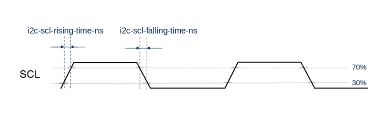
3.2.3. How to measure I2C timings[edit | edit source]
i2c-scl-rising-time-ns is measured on the SCL rising edge and i2c-scl-falling-time-ns on the SCL falling edge. On the oscilloscope, measure the time between the 30% to 70% range of amplitude for rising time and falling time in nanoseconds.
3.3. DT configuration examples[edit | edit source]
3.3.1. Example of the I2C timings applied on STM32MP257x-EV1 Evaluation board  [edit | edit source]
&i2c2 {
        pinctrl-names = "default", "sleep";
        pinctrl-0 = <&i2c2_pins_a>;
        pinctrl-1 = <&i2c2_sleep_pins_a>;
        i2c-scl-rising-time-ns = <100>;
        i2c-scl-falling-time-ns = <13>;
        clock-frequency = <400000>;
        status = "okay";
        /* spare dmas for other usage */
        /delete-property/dmas;
        /delete-property/dma-names;

        imx335: imx335@1a {
                 (...)
        };
};
The above example shows scl rising/falling time to be applied for the STM32MP257x-EV1 Evaluation board ![]() device tree file[11] for the i2c2 instance into which the camera module is connected.
device tree file[11] for the i2c2 instance into which the camera module is connected.
3.3.2. Example of an external EEPROM slave device[edit | edit source]
i2c4: {
    status = "okay";
    i2c-scl-rising-time-ns = <185>;
    i2c-scl-falling-time-ns = <20>;

    eeprom@50 {
        compatible = "at,24c256";
        pagesize = <64>;
        reg = <0x50>;
    };
};
The above example registers an EEPROM device on i2c-X bus (X depends on how many adapters are probed at runtime) at address 0x50 and this instance is compatible with the driver registered with the same compatible property.
Please note that the driver is going to use MDMA for data transfer and that SCL rising/falling times have been provided as inputs.
3.3.3. Example of an EEPROM slave device emulator registering on STM32 side[edit | edit source]
i2c4: {
    eeprom@64 {
        status = "okay";
        compatible = "linux,slave-24c02";
        reg = <0x40000064>;
    };
};
The above example registers an EEPROM emulator on STM32 side at slave address 0x64.
STM32 acts as an I2C EEPROM that can be accessed from an external master device connected on I2C bus.
3.3.4. Example of a stts751 thermal sensor with SMBus Alert feature enabled[edit | edit source]
The stts751 thermal sensor [12] is able to send an SMBus Alert when configured threshold are reached.
The device driver can be enabled in the kernel:
[x] Device Drivers
    [x] Hardware Monitoring support
        [x] ST Microelectronics STTS751
This can be done manually in your kernel:
CONFIG_SENSORS_STTS751=y
Since the SMBus Alert is relying on a dedicated pin to work, the pinctrl of the I2C controller (here i2c2) must be updated to add the corresponding SMBA pin.
For the i2c2 controller:
i2c2_pins_a: i2c2-0 {
    pins {
        pinmux = <STM32_PINMUX('H', 4, AF4)>, /* I2C2_SCL */
                 <STM32_PINMUX('H', 5, AF4)>, /* I2C2_SDA */
                 <STM32_PINMUX('H', 6, AF4)>; /* I2C2_SMBA */
        bias-disable;
        drive-open-drain;
        slew-rate = <0>;
    };
};

i2c2_pins_sleep_a: i2c2-1 {
    pins {
        pinmux = <STM32_PINMUX('H', 4, ANALOG)>, /* I2C2_SCL */
                 <STM32_PINMUX('H', 5, ANALOG)>, /* I2C2_SDA */
                 <STM32_PINMUX('H', 6, ANALOG)>; /* I2C2_SMBA */
    };
};
Within the device-tree, the st,smbus-alert property must be added, as well as the node to enable the stts751.
i2c2: {
    st,smbus-alert;
    stts751@3b {
        status = "okay";
        compatible = "stts751";
        reg = <0x3b>;
    };
};
4. How to configure the DT using STM32CubeMX[edit | edit source]
The STM32CubeMX tool can be used to configure the STM32MPU device and get the corresponding platform configuration device tree files.
The STM32CubeMX may not support all the properties described in the above DT bindings documentation paragraph. If so, the tool inserts user sections in the generated device tree. These sections can then be edited to add some properties and they are preserved from one generation to another. Refer to STM32CubeMX user manual for further information.
5. References[edit | edit source]
Please refer to the following links for additional information:
- ↑ I2C internal peripheral
- ↑ Device tree
- ↑ 3.0 3.1 Documentation/devicetree/bindings/i2c/i2c.txt , Generic device tree bindings for I2C busses
- ↑ Documentation/devicetree/bindings/i2c/st,stm32-i2c.yaml
- ↑ arch/arm/boot/dts/st/stm32mp131.dtsi
- ↑ arch/arm/boot/dts/st/stm32mp151.dtsi
- ↑ arch/arm64/boot/dts/st/stm32mp251.dtsi
- ↑ arch/arm64/boot/dts/st/stm32mp231.dtsi
- ↑ arch/arm64/boot/dts/st/stm32mp251.dtsi
- ↑ Documentation/i2c/smbus-protocol.rst
- ↑ Linux kernel device tree file stm32mp257f-ev1.dts for STM32MP257x-EV1 Evaluation board
- ↑ https://www.st.com/en/mems-and-sensors/stts751.html