1. Article purpose[edit | edit source]
The purpose of this article is to:
- introduce briefly the LVDS peripheral and its main features,
- indicate the peripheral instances assignment at boot time and their assignment at runtime (including whether instances can be allocated to secure contexts),
- list the software frameworks and drivers managing the peripheral,
- explain how to configure the peripheral.
2. Peripheral overview[edit | edit source]
The LVDS display interface transmitter (LVDS) handles the LVDS protocol. It maps the pixels received from the upstream Pixel-DMA (LTDC[1]) onto the LVDS PHY.
2.1. General characteristics[edit | edit source]
It regroups three subblocks.
- LVDS host: it handles the LVDS protocol (FPD-Link/OpenLDI) by mapping its input pixels onto the data lanes of the PHY.
- LVDS PHY: it parallelizes the data and drives the LVDS data lanes.
- LVDS wrapper: it handles the top-level settings.
The LVDS host supports the following high-level features:
- FPD-Link I and OpenLDI (v0.95) protocols
- Flexible bit-mapping, including JEIDA and VESA
- RGB888 or RGB666 output
- Synchronous design, with one input pixel per clock cycle
- No resolution limitation.
The LVDS PHY supports the following high-level features:
- FPD-Link bitrate: 784 Mbps/lane (112 Mpixel/s/link, 224 Mpixel/s if dual link)
- OpenLDI bitrate: 1100 Mbps/lane (157 Mpixel/s/link, 314 Mpixel/s if dual link)
Refer to the STM32 MPU reference manuals for the complete list of features, and to the software frameworks and drivers, introduced below, to see which features are implemented.
2.2. On STM32MP23x lines  [edit | edit source]
In addition to the general characteristics described above, the LVDS host supports the following high-level features:
- Single link operation
- Single display
2.3. On STM32MP25x lines [edit | edit source]
In addition to the general characteristics described above, the LVDS host supports the following high-level features:
- Single link or dual link operation
- Single display or double display (with the same content duplicated on both)
3. Peripheral usage[edit | edit source]
This chapter is applicable in the scope of the OpenSTLinux BSP running on the Arm® Cortex®-A processor(s), and the FwST-M Package running on the Arm® Cortex®-M processor.
3.1. Boot time assignment[edit | edit source]
The LVDS can be used at boot time for displaying a splash screen thanks to the U-Boot framework [2].
3.1.1. On STM32MP23x lines and STM32MP25x lines [edit | edit source]
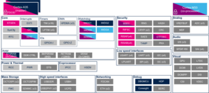
3.1.1.1. For A35-TD flavor  [edit | edit source]
Click on ![]() to expand or collapse the legend...
to expand or collapse the legend...
Check boxes illustrate the possible peripheral allocations supported by the OpenSTLinux BSP:
- ⬚ means that the peripheral can be assigned to the given boot time context, but this configuration is not supported in OpenSTLinux BSP.
- ☐ means that the peripheral can be assigned to the given boot time context.
- ☑ means that the peripheral is assigned by default to the given boot time context and that the peripheral is mandatory for the OpenSTLinux BSP.
- ✓ is used for system peripherals that cannot be unchecked because they are hardware connected in the device.
The present chapter describes STMicroelectronics recommendations or choice of implementation. Additional possibilities might be described in STM32 MPU reference manuals.
| Domain | Peripheral | Boot time allocation | Comment | |||
|---|---|---|---|---|---|---|
| Instance | Cortex-A35 secure (ROM code) |
Cortex-A35 secure (TF-A BL2) |
Cortex-A35 nonsecure (U-Boot) | |||
| Visual | LVDS | LVDS | ☐ | |||
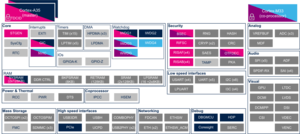
3.1.1.2. For M33-TD flavor [edit | edit source]
Click on ![]() to expand or collapse the legend...
to expand or collapse the legend...
Check boxes illustrate the possible peripheral allocations supported by the OpenSTLinux BSP:
- ⬚ means that the peripheral can be assigned to the given boot time context, but this configuration is not supported in OpenSTLinux BSP.
- ☐ means that the peripheral can be assigned to the given boot time context.
- ☑ means that the peripheral is assigned by default to the given boot time context and that the peripheral is mandatory for the OpenSTLinux BSP.
- ✓ is used for system peripherals that cannot be unchecked because they are hardware connected in the device.
The present chapter describes STMicroelectronics recommendations or choice of implementation. Additional possibilities might be described in STM32 MPU reference manuals.
| Domain | Peripheral | Boot time allocation | Comment | ||||
|---|---|---|---|---|---|---|---|
| Instance | Cortex-A35 secure (ROM code) |
Cortex-A35 secure (TF-A BL2) |
Cortex-A35 nonsecure (U-Boot) |
Cortex-M33 secure (MCUboot) | |||
| Visual | LVDS | LVDS | ☐ | ||||
3.2. Runtime assignment[edit | edit source]
3.2.1. On STM32MP23x lines [edit | edit source]
The table below is applicable to any TD flavor (A35-TD or M33-TD) ![]() .
.
Click on ![]() to expand or collapse the legend...
to expand or collapse the legend...
Check boxes illustrate the possible peripheral allocations supported by the OpenSTLinux BSP:
- ⬚ means that the peripheral can be assigned to the given runtime context, but this configuration is not supported in OpenSTLinux BSP.
- ☐ means that the peripheral can be assigned to the given runtime context.
- ☑ means that the peripheral is assigned by default to the given runtime context and that the peripheral is mandatory for the OpenSTLinux BSP.
- ✓ is used for system peripherals that cannot be unchecked because they are hardware connected in the device.
Refer to How to assign an internal peripheral to an execution context for more information on how to assign peripherals manually or via STM32CubeMX.
The present chapter describes STMicroelectronics recommendations or choice of implementation. Additional possibilities might be described in STM32MP23 reference manuals.
| Domain | Peripheral | Runtime allocation | Comment | ||||
|---|---|---|---|---|---|---|---|
| Instance | Cortex-A35 secure (OP-TEE / TF-A BL31) |
Cortex-A35 nonsecure (Linux) |
Cortex-M33 secure (TF-M) |
Cortex-M33 nonsecure (STM32Cube) | |||
| Visual | LVDS | LVDS | ⬚OP-TEE | ☐ | ⬚ | ☐ | |
3.2.2. On STM32MP25x lines [edit | edit source]
The table below is applicable to any TD flavor (A35-TD or M33-TD) ![]() .
.
Click on ![]() to expand or collapse the legend...
to expand or collapse the legend...
Check boxes illustrate the possible peripheral allocations supported by the OpenSTLinux BSP:
- ⬚ means that the peripheral can be assigned to the given runtime context, but this configuration is not supported in OpenSTLinux BSP.
- ☐ means that the peripheral can be assigned to the given runtime context.
- ☑ means that the peripheral is assigned by default to the given runtime context and that the peripheral is mandatory for the OpenSTLinux BSP.
- ✓ is used for system peripherals that cannot be unchecked because they are hardware connected in the device.
Refer to How to assign an internal peripheral to an execution context for more information on how to assign peripherals manually or via STM32CubeMX.
The present chapter describes STMicroelectronics recommendations or choice of implementation. Additional possibilities might be described in STM32MP25 reference manuals.
| Domain | Peripheral | Runtime allocation | Comment | |||||
|---|---|---|---|---|---|---|---|---|
| Instance | Cortex-A35 secure (OP-TEE / TF-A BL31) |
Cortex-A35 nonsecure (Linux) |
Cortex-M33 secure (TF-M) |
Cortex-M33 nonsecure (STM32Cube) |
Cortex-M0+ (STM32Cube) | |||
| Visual | LVDS | LVDS | ⬚OP-TEE | ☐ | ⬚ | ☐ | ||
4. Software frameworks and drivers[edit | edit source]
Below are listed the software frameworks and drivers managing the LVDS peripheral for the embedded software components listed in the above tables.
- Linux®:
- DRM/KMS framework
- Linux kernel: drivers/gpu/drm/stm/lvds.c
- U-Boot:
- STM32Cube:
5. How to assign and configure the peripheral[edit | edit source]
The peripheral assignment can be done via the STM32CubeMX graphical tool (and manually completed if needed).
This tool also helps to configure the peripheral by generating:
- Partial device trees (pin control and clock tree) for the OpenSTLinux software components,
- HAL initialization code for the STM32CubeMPU package.
The configuration is applied by the firmware running in the context in which the peripheral is assigned.
See also additional information in the LVDS device tree configuration article for Linux®.
6. How to go further[edit | edit source]
Refer to the STM32 MPU reference manuals for a detailed description of the LVDS peripheral and applicable use cases.
You may be interested in the following related articles:
7. References[edit | edit source]
Arm® is a registered trademark of Arm Limited (or its subsidiaries) in the US and/or elsewhere. ![]()
Arm® is a registered trademark of Arm Limited (or its subsidiaries) in the US and/or elsewhere. ![]()