1. Article purpose[edit | edit source]
The purpose of this article is to:
- briefly introduce the RCC peripheral and its main features,
- indicate the peripheral instances assignment at boot time and their assignment at runtime (including whether instances can be allocated to secure contexts),
- list the software frameworks and drivers managing the peripheral,
- explain how to configure the peripheral.
2. Peripheral overview[edit | edit source]
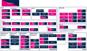
The RCC peripheral is used to manage the clock and reset generation for the complete circuit. The RCC gets several internal and external oscillators. They are used as clock sources for the hardware blocks, either directly or indirectly, via the PLLs that allow to achieve high frequencies.
The different features of RCC could be assigned to the execution contexts of the platform:
- On STM32MP13x lines
 , each resource/sub-function is allocated either to the secure world or to the non-secure world via bits in the RCC_SECCFGR register.
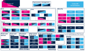
 - On STM32MP15x lines , there are two levels of security, which are controlled via two bits in the RCC_TZCR register (only accessible in secure mode):
- TZEN allows to set some RCC registers in secure mode, in particular registers for configuring PLL1 and PLL2, in order to secure a TrustZone perimeter for the Cortex®-A7 secure core and its peripherals.
- MCKPROT allows extending the TZEN secure clock control perimeter to PLL3 and to the MCU subsystem, so to the Cortex®-M4 and its bus clock.
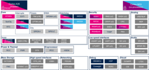
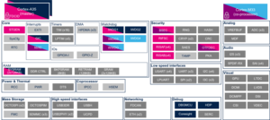
- On STM32MP2 series, RCC is a RIF-aware peripheral. That means
- Dedicated RCC features are protected by RIF protection embedded in RCC following peripheral firewall rules described in Resource Isolation Framework overview
- For internal peripherals protected by a RISUP, the protection for reset and clock gating control is inherited from RIFSC configuration
- Note:
- Clock gating registers of system resources (Internal RAM, RIF-aware peripherals) are protected by RCC RIF protection (no RIFSC inheritance). This allows to manage automatic clock gating according to either processor low power state or system low power state. Indeed, when a peripheral is shared, it should always be available to any execution context at any time.
Please note that all RCC registers can be read from any execution context.
Refer to the STM32 MPU reference manuals for the complete list of features, and to the software frameworks and drivers, introduced below, to see which features are implemented.
3. Peripheral usage[edit | edit source]
This chapter is applicable in the scope of the OpenSTLinux BSP running on the Arm® Cortex®-A processor(s), and the FwST-M Package running on the Arm® Cortex®-M processor.
3.1. Boot time assignment[edit | edit source]
3.1.1. On STM32MP1 series[edit | edit source]
The RCC is used by all the boot components: the ROM code, the FSBL, the SSBL and up to the Linux® kernel. Each component is able to reset and gate internal peripherals
FSBL is responsible to make a minimal clock tree initialization for loading the next boot stages. Then the main clock tree initialization step is performed by the OP-TEE secure OS: it consists in configuring all the input clocks, the PLLs and the clock sources that are selected as kernel clocks for all peripherals. The whole clock tree configuration is carried out by the device tree (see STM32MP13 clock tree and STM32MP15 clock tree).
Click on ![]() to expand or collapse the legend...
to expand or collapse the legend...
Check boxes illustrate the possible peripheral allocations supported by the OpenSTLinux BSP:
- ⬚ means that the peripheral can be assigned to the given boot time context, but this configuration is not supported in OpenSTLinux BSP.
- ☐ means that the peripheral can be assigned to the given boot time context.
- ☑ means that the peripheral is assigned by default to the given boot time context and that the peripheral is mandatory for the OpenSTLinux BSP.
- ✓ is used for system peripherals that cannot be unchecked because they are hardware connected in the device.
The present chapter describes STMicroelectronics recommendations or choice of implementation. Additional possibilities might be described in STM32 MPU reference manuals.
| Domain | Peripheral | Boot time allocation | Comment | |||
|---|---|---|---|---|---|---|
| Instance | Cortex-A7 secure (ROM code) |
Cortex-A7 secure (TF-A BL2) |
Cortex-A7 nonsecure (U-Boot) | |||
| Power & Thermal | RCC | RCC | ✓ | ✓ | ✓ | RCC peripheral is used by all boot components. More info here. |
3.1.2. On STM32MP2 series[edit | edit source]
3.1.2.1. For A35-TD flavor  [edit | edit source]
In A35-TD flavor ![]() , the RCC is used by all boot components: the ROM code, the Cortex-A FSBL, the Secure OS, the SSBL and the Linux® kernel. Each software component is able to reset and gate internal peripherals assigned to it.
, the RCC is used by all boot components: the ROM code, the Cortex-A FSBL, the Secure OS, the SSBL and the Linux® kernel. Each software component is able to reset and gate internal peripherals assigned to it.
ROM code clock tree configuration is fixed, mainly based on HSI internal oscillator. The goal is to configure in a safe mode the platform to load, authenticate and execute the FSBL.
The Cortex-A FSBL is responsible to make a minimal clock tree initialization for loading the next boot stages. Then the main clock tree initialization step is performed by the OP-TEE secure OS: it consists in configuring all the input clocks, the PLLs and the clock sources that are selected as kernel clocks for all peripherals. The whole clock tree configuration is carried out by the device tree (see STM32MP2 clock tree).
3.1.2.1.1. On STM32MP21x lines [edit | edit source]
Click on ![]() to expand or collapse the legend...
to expand or collapse the legend...
Check boxes illustrate the possible peripheral allocations supported by the OpenSTLinux BSP:
- ⬚ means that the peripheral can be assigned to the given boot time context, but this configuration is not supported in OpenSTLinux BSP.
- ☐ means that the peripheral can be assigned to the given boot time context.
- ☑ means that the peripheral is assigned by default to the given boot time context and that the peripheral is mandatory for the OpenSTLinux BSP.
- ✓ is used for system peripherals that cannot be unchecked because they are hardware connected in the device.
The present chapter describes STMicroelectronics recommendations or choice of implementation. Additional possibilities might be described in STM32 MPU reference manuals.
| Domain | Peripheral | Boot time allocation | Comment | |||
|---|---|---|---|---|---|---|
| Instance | Cortex-A35 secure (ROM code) |
Cortex-A35 secure (TF-A BL2) |
Cortex-A35 nonsecure (U-Boot) | |||
| Power & Thermal | RCC |
RCC | Shareable at internal peripheral level thanks to the RIF: see the boot time allocation per feature For internal peripherals protected by a RISUP, the protection for reset and clock gating control is inherited from RIFSC configuration. |
RCC peripheral is used by all boot components. More info here. | ||
The below table shows the possible boot time allocations for the features of the RCC instance on STM32MP21x lines ![]() for A35-TD flavor
for A35-TD flavor ![]() .
.
| Feature | Boot time allocation |
Comment | ||
|---|---|---|---|---|
| Cortex-A35 secure (ROM code) |
Cortex-A35 secure (TF-A BL2) |
Cortex-A35 nonsecure (U-Boot) | ||
| FCALC | ⬚ | |||
| SYSRST | ✓ | ⬚ | ||
| BOOT_STDB | ✓ | ⬚ | ||
| RDCR | ✓ | ⬚ | ||
| SYSCLK | ✓ | ⬚ | ||
| CPU1_RES | ✓ | ✓ | ⬚ | |
| CPU2_RES | ||||
| DEBUG_CFGR | ☐ | ⬚ | ||
| SYSRAM_CFGR | ✓ | ☑ | ||
| RETRAM_CFGR | ⬚ | ⬚ | ||
| BKPSRAM_CFGR | ⬚ | ⬚ | ||
| SRAM1_CFGR | ⬚ | ⬚ | ||
| HPDMA1_CFGR | ⬚ | ⬚ | ||
| HPDMA2_CFGR | ⬚ | ⬚ | ||
| HPDMA3_CFGR | ⬚ | ⬚ | ||
| IPCC1_CFGR | ⬚ | ☐ | ||
| GPIOA_CFGR | ☑ | ☐ | ||
| GPIOB_CFGR | ☑ | ☐ | ||
| GPIOC_CFGR | ☑ | ☐ | ||
| GPIOD_CFGR | ☑ | ☐ | ||
| GPIOE_CFGR | ☑ | ☐ | ||
| GPIOF_CFGR | ☑ | ☐ | ||
| GPIOG_CFGR | ☑ | ☐ | ||
| GPIOH_CFGR | ☑ | ☐ | ||
| GPIOI_CFGR | ☑ | ☐ | ||
| GPIOZ_CFGR | ☑ | ☐ | ||
| RTC_CFGR | ☐ | ☐ | ||
| BSEC_CFGR | ✓ | ☑ | ||
| DDRC_CFGR | ☑ | |||
| SYSCPU1_CFGR | ✓ | |||
| MCO1_CFGR | ⬚ | ⬚ | ||
| MCO2_CFGR | ⬚ | ⬚ | ||
| OSPI1_CFGR | ☐ | ☐ | ||
| FMC_CFGR | ☐ | ☐ | ☐ | |
| HSI_MON | ⬚ | ☐ | ||
3.1.2.1.2. On STM32MP23x lines [edit | edit source]
Click on ![]() to expand or collapse the legend...
to expand or collapse the legend...
Check boxes illustrate the possible peripheral allocations supported by the OpenSTLinux BSP:
- ⬚ means that the peripheral can be assigned to the given boot time context, but this configuration is not supported in OpenSTLinux BSP.
- ☐ means that the peripheral can be assigned to the given boot time context.
- ☑ means that the peripheral is assigned by default to the given boot time context and that the peripheral is mandatory for the OpenSTLinux BSP.
- ✓ is used for system peripherals that cannot be unchecked because they are hardware connected in the device.
The present chapter describes STMicroelectronics recommendations or choice of implementation. Additional possibilities might be described in STM32 MPU reference manuals.
| Domain | Peripheral | Boot time allocation | Comment | |||
|---|---|---|---|---|---|---|
| Instance | Cortex-A35 secure (ROM code) |
Cortex-A35 secure (TF-A BL2) |
Cortex-A35 nonsecure (U-Boot) | |||
| Power & Thermal | RCC |
RCC | Shareable at internal peripheral level thanks to the RIF: see the boot time allocation per feature For internal peripherals protected by a RISUP, the protection for reset and clock gating control is inherited from RIFSC configuration. |
RCC peripheral is used by all boot components. More info here. | ||
The below table shows the possible boot time allocations for the features of the RCC instance STM32MP23x lines ![]() for A35-TD flavor
for A35-TD flavor ![]() .
.
| Feature | Boot time allocation |
Comment | ||
|---|---|---|---|---|
| Cortex-A35 secure (ROM code) |
Cortex-A35 secure (TF-A BL2) |
Cortex-A35 nonsecure (U-Boot) | ||
| FCALC | ⬚ | |||
| SYSRST | ✓ | ⬚ | ||
| BOOT_STDB | ✓ | ⬚ | ||
| RDCR | ✓ | ⬚ | ||
| SYSCLK | ✓ | ⬚ | ||
| CPU1_RES | ✓ | ✓ | ⬚ | |
| CPU2_RES | ||||
| DEBUG_CFGR | ☐ | ⬚ | ||
| SYSRAM_CFGR | ✓ | ☑ | ||
| VDERAM_CFGR | ⬚ | ⬚ | ||
| RETRAM_CFGR | ⬚ | ⬚ | ||
| BKPSRAM_CFGR | ⬚ | ⬚ | ||
| SRAM1_CFGR | ⬚ | ⬚ | ||
| SRAM2_CFGR | ⬚ | ⬚ | ||
| HPDMA1_CFGR | ⬚ | ⬚ | ||
| HPDMA2_CFGR | ⬚ | ⬚ | ||
| HPDMA3_CFGR | ⬚ | ⬚ | ||
| IPCC1_CFGR | ⬚ | ☐ | ||
| IPCC2_CFGR | ⬚ | ☐ | ||
| HSEM_CFGR | ⬚ | ⬚ | ||
| GPIOA_CFGR | ☑ | ☐ | ||
| GPIOB_CFGR | ☑ | ☐ | ||
| GPIOC_CFGR | ☑ | ☐ | ||
| GPIOD_CFGR | ☑ | ☐ | ||
| GPIOE_CFGR | ☑ | ☐ | ||
| GPIOF_CFGR | ☑ | ☐ | ||
| GPIOG_CFGR | ☑ | ☐ | ||
| GPIOH_CFGR | ☑ | ☐ | ||
| GPIOI_CFGR | ☑ | ☐ | ||
| GPIOJ_CFGR | ☑ | ☐ | ||
| GPIOK_CFGR | ☑ | ☐ | ||
| GPIOZ_CFGR | ☑ | ☐ | ||
| RTC_CFGR | ☐ | ☐ | ||
| BSEC_CFGR | ✓ | ☑ | ||
| DDRC_CFGR | ☑ | |||
| PLL3_CFGR | ⬚ | |||
| SYSCPU1_CFGR | ✓ | |||
| MCO1_CFGR | ⬚ | ⬚ | ||
| MCO2_CFGR | ⬚ | ⬚ | ||
| OSPI1_CFGR | ☐ | ☐ | ||
| OSPI2_CFGR | ☐ | ☐ | ||
| FMC_CFGR | ☐ | ☐ | ☐ | |
| HSI_MON | ⬚ | ☐ | ||
3.1.2.1.3. On STM32MP25x lines [edit | edit source]
Click on ![]() to expand or collapse the legend...
to expand or collapse the legend...
Check boxes illustrate the possible peripheral allocations supported by the OpenSTLinux BSP:
- ⬚ means that the peripheral can be assigned to the given boot time context, but this configuration is not supported in OpenSTLinux BSP.
- ☐ means that the peripheral can be assigned to the given boot time context.
- ☑ means that the peripheral is assigned by default to the given boot time context and that the peripheral is mandatory for the OpenSTLinux BSP.
- ✓ is used for system peripherals that cannot be unchecked because they are hardware connected in the device.
The present chapter describes STMicroelectronics recommendations or choice of implementation. Additional possibilities might be described in STM32 MPU reference manuals.
| Domain | Peripheral | Boot time allocation | Comment | |||
|---|---|---|---|---|---|---|
| Instance | Cortex-A35 secure (ROM code) |
Cortex-A35 secure (TF-A BL2) |
Cortex-A35 nonsecure (U-Boot) | |||
| Power & Thermal | RCC |
RCC | Shareable at internal peripheral level thanks to the RIF: see the boot time allocation per feature For internal peripherals protected by a RISUP, the protection for reset and clock gating control is inherited from RIFSC configuration. |
RCC peripheral is used by all boot components. More info here. | ||
The below table shows the possible boot time allocations for the features of the RCC instance STM32MP25x lines ![]() for A35-TD flavor
for A35-TD flavor ![]() .
.
| Feature | Boot time allocation |
Comment | ||
|---|---|---|---|---|
| Cortex-A35 secure (ROM code) |
Cortex-A35 secure (TF-A BL2) |
Cortex-A35 nonsecure (U-Boot) | ||
| FCALC | ⬚ | |||
| SYSRST | ✓ | ⬚ | ||
| BOOT_STDB | ✓ | ⬚ | ||
| RDCR | ✓ | ⬚ | ||
| SYSCLK | ✓ | ⬚ | ||
| CPU1_RES | ✓ | ✓ | ⬚ | |
| CPU2_RES | ||||
| CPU3_RES | ☐ | |||
| DEBUG_CFGR | ☐ | ⬚ | ||
| SYSRAM_CFGR | ✓ | ☑ | ||
| VDERAM_CFGR | ⬚ | ⬚ | ||
| RETRAM_CFGR | ⬚ | ⬚ | ||
| BKPSRAM_CFGR | ⬚ | ⬚ | ||
| SRAM1_CFGR | ⬚ | ⬚ | ||
| SRAM2_CFGR | ⬚ | ⬚ | ||
| LPSRAM1_CFGR | ⬚ | |||
| LPSRAM2_CFGR | ⬚ | |||
| LPSRAM3_CFGR | ⬚ | |||
| HPDMA1_CFGR | ⬚ | ⬚ | ||
| HPDMA2_CFGR | ⬚ | ⬚ | ||
| HPDMA3_CFGR | ⬚ | ⬚ | ||
| LPDMA_CFGR | ⬚ | ⬚ | ||
| IPCC1_CFGR | ⬚ | ☐ | ||
| IPCC2_CFGR | ⬚ | ☐ | ||
| HSEM_CFGR | ⬚ | ⬚ | ||
| GPIOA_CFGR | ☑ | ☐ | ||
| GPIOB_CFGR | ☑ | ☐ | ||
| GPIOC_CFGR | ☑ | ☐ | ||
| GPIOD_CFGR | ☑ | ☐ | ||
| GPIOE_CFGR | ☑ | ☐ | ||
| GPIOF_CFGR | ☑ | ☐ | ||
| GPIOG_CFGR | ☑ | ☐ | ||
| GPIOH_CFGR | ☑ | ☐ | ||
| GPIOI_CFGR | ☑ | ☐ | ||
| GPIOJ_CFGR | ☑ | ☐ | ||
| GPIOK_CFGR | ☑ | ☐ | ||
| GPIOZ_CFGR | ☑ | ☐ | ||
| RTC_CFGR | ☐ | ☐ | ||
| BSEC_CFGR | ✓ | ☑ | ||
| DDRC_CFGR | ☑ | |||
| PLL3_CFGR | ⬚ | |||
| SYSCPU1_CFGR | ✓ | |||
| MCO1_CFGR | ⬚ | ⬚ | ||
| MCO2_CFGR | ⬚ | ⬚ | ||
| OSPI1_CFGR | ☐ | ☐ | ||
| OSPI2_CFGR | ☐ | ☐ | ||
| FMC_CFGR | ☐ | ☐ | ☐ | |
| HSI_MON | ⬚ | ☐ | ||
3.1.2.2. For M33-TD flavor [edit | edit source]
In M33-TD flavor ![]() , the RCC is used by all the boot components: the ROM code, the Cortex-M33 FSBL ( MCUboot), the Cortex-M33 secure OS (TF-M) and once system initialized, when the Arm Cortex-A35 is started by Cortex-A FSBL, the Cortex-A secure OS, the Cortex-A SSBL and the Linux® kernel. Each SW component is able to reset and gate internal peripherals assigned to it.
, the RCC is used by all the boot components: the ROM code, the Cortex-M33 FSBL ( MCUboot), the Cortex-M33 secure OS (TF-M) and once system initialized, when the Arm Cortex-A35 is started by Cortex-A FSBL, the Cortex-A secure OS, the Cortex-A SSBL and the Linux® kernel. Each SW component is able to reset and gate internal peripherals assigned to it.
ROM code clock tree configuration is fixed, mainly based on HSI internal oscillator. The goal is to configure in a safe mode the platform to load, authenticate and execute the Cortex-M FSBL on cold boot.
The Cortex-M FSBL is responsible to make a minimal clock tree initialization for loading the next boot stages. Then the main clock tree initialization step is performed by the TF-M secure OS: it consists in configuring all the input clocks, the PLLs and the clock sources that are selected as kernel clocks for all peripherals. The whole clock tree configuration is carried out by the device tree (see STM32MP2 clock tree).
The ROM code update the initial clock tree (see STM32 MPU ROM code overview for details) when it load, authenticate and execute the Cortex-A FSBL.
3.1.2.2.1. On STM32MP21x lines [edit | edit source]
Click on ![]() to expand or collapse the legend...
to expand or collapse the legend...
Check boxes illustrate the possible peripheral allocations supported by the OpenSTLinux BSP:
- ⬚ means that the peripheral can be assigned to the given boot time context, but this configuration is not supported in OpenSTLinux BSP.
- ☐ means that the peripheral can be assigned to the given boot time context.
- ☑ means that the peripheral is assigned by default to the given boot time context and that the peripheral is mandatory for the OpenSTLinux BSP.
- ✓ is used for system peripherals that cannot be unchecked because they are hardware connected in the device.
The present chapter describes STMicroelectronics recommendations or choice of implementation. Additional possibilities might be described in STM32 MPU reference manuals.
| Domain | Peripheral | Boot time allocation | Comment | ||||
|---|---|---|---|---|---|---|---|
| Instance | Cortex-A35 secure (ROM code) |
Cortex-A35 secure (TF-A BL2) |
Cortex-A35 nonsecure (U-Boot) |
Cortex-M33 secure (MCUboot) | |||
| Power & Thermal | RCC |
RCC | Shareable at internal peripheral level thanks to the RIF: see the boot time allocation per feature For internal peripherals protected by a RISUP, the protection for reset and clock gating control is inherited from RIFSC configuration |
RCC peripheral is used by all boot components. More info here | |||
The below table shows the possible boot time allocations for the features of the RCC instance on STM32MP21x lines ![]() for M33-TD flavor
for M33-TD flavor ![]() .
.
| Feature | Boot time allocation |
Comment | |||
|---|---|---|---|---|---|
| Cortex-A35 secure (ROM code) |
Cortex-A35 secure (TF-A BL2) |
Cortex-A35 nonsecure (U-Boot) |
Cortex-M33 secure (MCUboot) | ||
| FCALC | ⬚ | ||||
| SYSRST | ✓ | ||||
| BOOT_STDB | ✓ | ||||
| RDCR | ✓ | ||||
| SYSCLK | ✓ | ||||
| CPU1_RES | ✓ | ✓ | ⬚ | ||
| CPU2_RES | ✓ | ||||
| DEBUG_CFGR | ⬚ | ⬚ | |||
| SYSRAM_CFGR | ✓ | ☐ | |||
| RETRAM_CFGR | ⬚ | ⬚ | ✓ | ||
| BKPSRAM_CFGR | ⬚ | ⬚ | ☐ | ||
| SRAM1_CFGR | ⬚ | ⬚ | ☐ | ||
| HPDMA1_CFGR | ⬚ | ||||
| HPDMA2_CFGR | ⬚ | ||||
| HPDMA3_CFGR | ⬚ | ||||
| IPCC1_CFGR | ⬚ | ||||
| GPIOA_CFGR | ⬚ | ⬚ | ☑ | ||
| GPIOB_CFGR | ⬚ | ⬚ | ☑ | ||
| GPIOC_CFGR | ⬚ | ⬚ | ☑ | ||
| GPIOD_CFGR | ⬚ | ⬚ | ☑ | ||
| GPIOE_CFGR | ⬚ | ⬚ | ☑ | ||
| GPIOF_CFGR | ⬚ | ⬚ | ☑ | ||
| GPIOG_CFGR | ⬚ | ⬚ | ☑ | ||
| GPIOH_CFGR | ⬚ | ⬚ | ☑ | ||
| GPIOI_CFGR | ⬚ | ⬚ | ☑ | ||
| GPIOZ_CFGR | ⬚ | ⬚ | ☑ | ||
| RTC_CFGR | ⬚ | ⬚ | ☑ | ||
| BSEC_CFGR | ✓ | ⬚ | ☑ | ||
| DDRC_CFGR | ⬚ | ⬚ | ☑ | ||
| SYSCPU1_CFGR | ☐ | ||||
| MCO1_CFGR | ⬚ | ⬚ | ⬚ | ||
| MCO2_CFGR | ⬚ | ⬚ | ⬚ | ||
| OSPI1_CFGR | ⬚ | ⬚ | ☐ | ||
| FMC_CFGR | ☐ | ☐ | ⬚ | ||
| HSI_MON | ⬚ | ⬚ | ⬚ | ||
3.1.2.2.2. On STM32MP23x lines [edit | edit source]
Click on ![]() to expand or collapse the legend...
to expand or collapse the legend...
Check boxes illustrate the possible peripheral allocations supported by the OpenSTLinux BSP:
- ⬚ means that the peripheral can be assigned to the given boot time context, but this configuration is not supported in OpenSTLinux BSP.
- ☐ means that the peripheral can be assigned to the given boot time context.
- ☑ means that the peripheral is assigned by default to the given boot time context and that the peripheral is mandatory for the OpenSTLinux BSP.
- ✓ is used for system peripherals that cannot be unchecked because they are hardware connected in the device.
The present chapter describes STMicroelectronics recommendations or choice of implementation. Additional possibilities might be described in STM32 MPU reference manuals.
| Domain | Peripheral | Boot time allocation | Comment | ||||
|---|---|---|---|---|---|---|---|
| Instance | Cortex-A35 secure (ROM code) |
Cortex-A35 secure (TF-A BL2) |
Cortex-A35 nonsecure (U-Boot) |
Cortex-M33 secure (MCUboot) | |||
| Power & Thermal | RCC |
RCC | Shareable at internal peripheral level thanks to the RIF: see the boot time allocation per feature For internal peripherals protected by a RISUP, the protection for reset and clock gating control is inherited from RIFSC configuration |
RCC peripheral is used by all boot components. More info here | |||
The below table shows the possible boot time allocations for the features of the RCC instance on STM32MP23x lines ![]() for M33-TD flavor
for M33-TD flavor ![]() .
.
| Feature | Boot time allocation |
Comment | |||
|---|---|---|---|---|---|
| Cortex-A35 secure (ROM code) |
Cortex-A35 secure (TF-A BL2) |
Cortex-A35 nonsecure (U-Boot) |
Cortex-M33 secure (MCUboot) | ||
| FCALC | ⬚ | ||||
| SYSRST | ✓ | ||||
| BOOT_STDB | ✓ | ||||
| RDCR | ✓ | ||||
| SYSCLK | ✓ | ||||
| CPU1_RES | ✓ | ✓ | ⬚ | ||
| CPU2_RES | ✓ | ||||
| DEBUG_CFGR | ⬚ | ⬚ | |||
| SYSRAM_CFGR | ✓ | ☐ | |||
| VDERAM_CFGR | ⬚ | ⬚ | ⬚ | ||
| RETRAM_CFGR | ⬚ | ⬚ | ✓ | ||
| BKPSRAM_CFGR | ⬚ | ⬚ | ☐ | ||
| SRAM1_CFGR | ⬚ | ⬚ | ☐ | ||
| SRAM2_CFGR | ⬚ | ⬚ | ☐ | ||
| HPDMA1_CFGR | ⬚ | ||||
| HPDMA2_CFGR | ⬚ | ||||
| HPDMA3_CFGR | ⬚ | ||||
| IPCC1_CFGR | ⬚ | ||||
| IPCC2_CFGR | ⬚ | ||||
| HSEM_CFGR | ⬚ | ||||
| GPIOA_CFGR | ☐ | ☐ | ☑ | ||
| GPIOB_CFGR | ☐ | ☐ | ☑ | ||
| GPIOC_CFGR | ☐ | ☐ | ☑ | ||
| GPIOD_CFGR | ☐ | ☐ | ☑ | ||
| GPIOE_CFGR | ☐ | ☐ | ☑ | ||
| GPIOF_CFGR | ☐ | ☐ | ☑ | ||
| GPIOG_CFGR | ☐ | ☐ | ☑ | ||
| GPIOH_CFGR | ☐ | ☐ | ☑ | ||
| GPIOI_CFGR | ☐ | ☐ | ☑ | ||
| GPIOJ_CFGR | ☐ | ☐ | ☑ | ||
| GPIOK_CFGR | ☐ | ☐ | ☑ | ||
| GPIOZ_CFGR | ☐ | ☐ | ☑ | ||
| RTC_CFGR | ☐ | ☐ | ☑ | ||
| BSEC_CFGR | ✓ | ☐ | ☑ | ||
| DDRC_CFGR | ⬚ | ⬚ | ☑ | ||
| PLL3_CFGR | ⬚ | ||||
| SYSCPU1_CFGR | ☐ | ||||
| MCO1_CFGR | ⬚ | ⬚ | ⬚ | ||
| MCO2_CFGR | ⬚ | ⬚ | ⬚ | ||
| OSPI1_CFGR | ☐ | ⬚ | ⬚ | ☐ | |
| OSPI2_CFGR | ⬚ | ⬚ | ☐ | ||
| FMC_CFGR | ☐ | ☐ | ☐ | ⬚ | |
| HSI_MON | ⬚ | ⬚ | ⬚ | ||
3.1.2.2.3. On STM32MP25x lines [edit | edit source]
Click on ![]() to expand or collapse the legend...
to expand or collapse the legend...
Check boxes illustrate the possible peripheral allocations supported by the OpenSTLinux BSP:
- ⬚ means that the peripheral can be assigned to the given boot time context, but this configuration is not supported in OpenSTLinux BSP.
- ☐ means that the peripheral can be assigned to the given boot time context.
- ☑ means that the peripheral is assigned by default to the given boot time context and that the peripheral is mandatory for the OpenSTLinux BSP.
- ✓ is used for system peripherals that cannot be unchecked because they are hardware connected in the device.
The present chapter describes STMicroelectronics recommendations or choice of implementation. Additional possibilities might be described in STM32 MPU reference manuals.
| Domain | Peripheral | Boot time allocation | Comment | ||||
|---|---|---|---|---|---|---|---|
| Instance | Cortex-A35 secure (ROM code) |
Cortex-A35 secure (TF-A BL2) |
Cortex-A35 nonsecure (U-Boot) |
Cortex-M33 secure (MCUboot) | |||
| Power & Thermal | RCC |
RCC | Shareable at internal peripheral level thanks to the RIF: see the boot time allocation per feature For internal peripherals protected by a RISUP, the protection for reset and clock gating control is inherited from RIFSC configuration |
RCC peripheral is used by all boot components. More info here | |||
The below table shows the possible boot time allocations for the features of the RCC instance on STM32MP25x lines ![]() for M33-TD flavor
for M33-TD flavor ![]() .
.
| Feature | Boot time allocation |
Comment | |||
|---|---|---|---|---|---|
| Cortex-A35 secure (ROM code) |
Cortex-A35 secure (TF-A BL2) |
Cortex-A35 nonsecure (U-Boot) |
Cortex-M33 secure (MCUboot) | ||
| FCALC | ⬚ | ||||
| SYSRST | ✓ | ||||
| BOOT_STDB | ✓ | ||||
| RDCR | ✓ | ||||
| SYSCLK | ✓ | ||||
| CPU1_RES | ✓ | ✓ | ⬚ | ||
| CPU2_RES | ✓ | ||||
| CPU3_RES | ⬚ | ||||
| DEBUG_CFGR | ⬚ | ⬚ | |||
| SYSRAM_CFGR | ✓ | ☐ | |||
| VDERAM_CFGR | ⬚ | ⬚ | ⬚ | ||
| RETRAM_CFGR | ⬚ | ⬚ | ✓ | ||
| BKPSRAM_CFGR | ⬚ | ⬚ | ☐ | ||
| SRAM1_CFGR | ⬚ | ⬚ | ☐ | ||
| SRAM2_CFGR | ⬚ | ⬚ | ☐ | ||
| LPSRAM1_CFGR | ⬚ | ⬚ | |||
| LPSRAM2_CFGR | ⬚ | ⬚ | |||
| LPSRAM3_CFGR | ⬚ | ⬚ | |||
| HPDMA1_CFGR | ⬚ | ||||
| HPDMA2_CFGR | ⬚ | ||||
| HPDMA3_CFGR | ⬚ | ||||
| LPDMA_CFGR | ⬚ | ||||
| IPCC1_CFGR | ⬚ | ||||
| IPCC2_CFGR | ⬚ | ||||
| HSEM_CFGR | ⬚ | ||||
| GPIOA_CFGR | ☐ | ☐ | ☑ | ||
| GPIOB_CFGR | ☐ | ☐ | ☑ | ||
| GPIOC_CFGR | ☐ | ☐ | ☑ | ||
| GPIOD_CFGR | ☐ | ☐ | ☑ | ||
| GPIOE_CFGR | ☐ | ☐ | ☑ | ||
| GPIOF_CFGR | ☐ | ☐ | ☑ | ||
| GPIOG_CFGR | ☐ | ☐ | ☑ | ||
| GPIOH_CFGR | ☐ | ☐ | ☑ | ||
| GPIOI_CFGR | ☐ | ☐ | ☑ | ||
| GPIOJ_CFGR | ☐ | ☐ | ☑ | ||
| GPIOK_CFGR | ☐ | ☐ | ☑ | ||
| GPIOZ_CFGR | ☐ | ☐ | ☑ | ||
| RTC_CFGR | ☐ | ☐ | ☑ | ||
| BSEC_CFGR | ✓ | ☐ | ☑ | ||
| DDRC_CFGR | ⬚ | ⬚ | ☑ | ||
| PLL3_CFGR | ⬚ | ||||
| SYSCPU1_CFGR | ☐ | ||||
| MCO1_CFGR | ⬚ | ⬚ | ⬚ | ||
| MCO2_CFGR | ⬚ | ⬚ | ⬚ | ||
| OSPI1_CFGR | ☐ | ⬚ | ⬚ | ☐ | |
| OSPI2_CFGR | ☐ | ⬚ | ⬚ | ||
| FMC_CFGR | ☐ | ☐ | ☐ | ⬚ | |
| HSI_MON | ⬚ | ⬚ | ⬚ | ||
3.2. Runtime assignment[edit | edit source]
3.2.1. On STM32MP1 series[edit | edit source]
The Arm® Cortex®-A7 secure core controls all the secure registers through the RCC OP-TEE driver. The access to some secure registers from the Cortex®-A7 non-secure core can be achieved via SCMI requests.
3.2.1.1. On STM32MP13x lines [edit | edit source]
Click on ![]() to expand or collapse the legend...
to expand or collapse the legend...
Check boxes illustrate the possible peripheral allocations supported by the OpenSTLinux BSP:
- ⬚ means that the peripheral can be assigned to the given runtime context, but this configuration is not supported in OpenSTLinux BSP.
- ☐ means that the peripheral can be assigned to the given runtime context.
- ☑ means that the peripheral is assigned by default to the given runtime context and that the peripheral is mandatory for the OpenSTLinux BSP.
- ✓ is used for system peripherals that cannot be unchecked because they are hardware connected in the device.
Refer to How to assign an internal peripheral to an execution context for more information on how to assign peripherals manually or via STM32CubeMX.
The present chapter describes STMicroelectronics recommendations or choice of implementation. Additional possibilities might be described in STM32MP13 reference manuals.
| Domain | Peripheral | Runtime allocation | Comment | ||
|---|---|---|---|---|---|
| Instance | Cortex-A7 secure (OP-TEE) |
Cortex-A7 nonsecure (Linux) | |||
| Power & Thermal | RCC | RCC | ✓ | ✓ | |
3.2.1.2. On STM32MP15x lines [edit | edit source]
Click on ![]() to expand or collapse the legend...
to expand or collapse the legend...
Check boxes illustrate the possible peripheral allocations supported by the OpenSTLinux BSP:
- ⬚ means that the peripheral can be assigned to the given runtime context, but this configuration is not supported in OpenSTLinux BSP.
- ☐ means that the peripheral can be assigned to the given runtime context.
- ☑ means that the peripheral is assigned by default to the given runtime context and that the peripheral is mandatory for the OpenSTLinux BSP.
- ✓ is used for system peripherals that cannot be unchecked because they are hardware connected in the device.
Refer to How to assign an internal peripheral to an execution context for more information on how to assign peripherals manually or via STM32CubeMX.
The present chapter describes STMicroelectronics recommendations or choice of implementation. Additional possiblities might be described in STM32MP15 reference manuals.
| Domain | Peripheral | Runtime allocation | Comment | |||
|---|---|---|---|---|---|---|
| Instance | Cortex-A7 secure (OP-TEE) |
Cortex-A7 nonsecure (Linux) |
Cortex-M4 (STM32Cube) | |||
| Power & Thermal | RCC | RCC | ✓ | ✓ | ✓ | |
3.2.2. On STM32MP2 series[edit | edit source]
The RCC system resources are resources which are shared between execution contexts or between different internal peripherals, like oscillators, PLLs, root clocks or reset and clock gating of RIF-aware peripherals.
In A35-TD flavor ![]() , the Cortex-A secure OS OP-TEE controls all these resources and provides SCMI services to access system resources.
, the Cortex-A secure OS OP-TEE controls all these resources and provides SCMI services to access system resources.
In M33-TD flavor ![]() , the Cortex-M secure OS TF-M controls all theses RCC system resources and provides SCMI services to access system resources.
, the Cortex-M secure OS TF-M controls all theses RCC system resources and provides SCMI services to access system resources.
RCC is a "RIF-aware component": all RCC resources are protected by the RIF configuration with:
- local configuration of RCC RIF resources, with features described in the next arrays "runtime allocation per feature"
- external configuration inherited from the RIF peripheral configuration to control reset and clock gating of peripheral protected by a RISUP: a SW component can write to the RCC related registers (RCC_PERxCFG) only when the associated peripheral is accessible for its runtime context
3.2.2.1. On STM32MP21x lines [edit | edit source]
3.2.2.1.1. For A35-TD flavor [edit | edit source]
Click on ![]() to expand or collapse the legend...
to expand or collapse the legend...
Check boxes illustrate the possible peripheral allocations supported by the OpenSTLinux BSP:
- ⬚ means that the peripheral can be assigned to the given runtime context, but this configuration is not supported in OpenSTLinux BSP.
- ☐ means that the peripheral can be assigned to the given runtime context.
- ☑ means that the peripheral is assigned by default to the given runtime context and that the peripheral is mandatory for the OpenSTLinux BSP.
- ✓ is used for system peripherals that cannot be unchecked because they are hardware connected in the device.
Refer to How to assign an internal peripheral to an execution context for more information on how to assign peripherals manually or via STM32CubeMX.
The present chapter describes STMicroelectronics recommendations or choice of implementation. Additional possibilities might be described in STM32MP21 reference manuals.
| Domain | Peripheral | Runtime allocation | Comment | ||||
|---|---|---|---|---|---|---|---|
| Instance | Cortex-A35 secure (OP-TEE / TF-A BL31) |
Cortex-A35 nonsecure (Linux) |
Cortex-M33 secure (TF-M) |
Cortex-M33 nonsecure (STM32Cube) | |||
| Power & Thermal | RCC |
RCC | Shareable at internal peripheral level thanks to the RIF: see the runtime allocation per feature. For internal peripherals protected by a RISUP, the protection for reset and clock gating control is inherited from RIFSC configuration. |
RCC peripheral is used by all software components. More info here. The Cortex-A secure OS OP-TEE controls the system resources and provides SCMI services. | |||
The below table shows the possible runtime allocations for the features of the RCC instance on STM32MP21x lines ![]() for A35-TD flavor
for A35-TD flavor ![]() .
.
| Feature | Runtime allocation |
Comment | |||
|---|---|---|---|---|---|
| Cortex-A35 secure (OP-TEE / TF-A BL31) |
Cortex-A35 nonsecure (Linux) |
Cortex-M33 secure (TF-M) |
Cortex-M33 nonsecure (STM32Cube) | ||
| FCALC | ☑OP-TEE | ⬚ | ☐ | ⬚ | |
| SYSRST | ✓OP-TEE ✓TF-A BL31 |
⬚ | |||
| BOOT_STDB | ✓OP-TEE ✓TF-A BL31 |
⬚ | |||
| RDCR | ✓OP-TEE ✓TF-A BL31 |
⬚ | |||
| SYSCLK | ✓OP-TEE ✓TF-A BL31 |
⬚ | |||
| CPU1_RES | ✓OP-TEE ✓TF-A BL31 |
||||
| CPU2_RES | ☐ if TZ_EN | ☐ if TZ_DIS | |||
| DEBUG_CFGR | ☑OP-TEE | ☐ | ☐ | ☐ | |
| SYSRAM_CFGR | ☑OP-TEE ☑TF-A BL31 |
||||
| RETRAM_CFGR | ☐OP-TEE ☑TF-A BL31 |
☐ | ☐ | ☐ | |
| BKPSRAM_CFGR | ☑OP-TEE ☑TF-A BL31 |
☐ | ☐ | ☐ | |
| SRAM1_CFGR | ☐OP-TEE | ☐ | ☐ | ☐ | |
| HPDMA1_CFGR | ☐OP-TEE | ☐ | ☐ | ☐ | |
| HPDMA2_CFGR | ☐OP-TEE | ☐ | ☐ | ☐ | |
| HPDMA3_CFGR | ☐OP-TEE | ☐ | ☐ | ☐ | |
| IPCC1_CFGR | ☑OP-TEE | ☐ | ☐ | ☐ | |
| GPIOA_CFGR | ☑OP-TEE ☑TF-A BL31 |
☐ | ☐ | ☐ | |
| GPIOB_CFGR | ☑OP-TEE ☑TF-A BL31 |
☐ | ☐ | ☐ | |
| GPIOC_CFGR | ☑OP-TEE ☑TF-A BL31 |
☐ | ☐ | ☐ | |
| GPIOD_CFGR | ☑OP-TEE ☑TF-A BL31 |
☐ | ☐ | ☐ | |
| GPIOE_CFGR | ☑OP-TEE ☑TF-A BL31 |
☐ | ☐ | ☐ | |
| GPIOF_CFGR | ☑OP-TEE ☑TF-A BL31 |
☐ | ☐ | ☐ | |
| GPIOG_CFGR | ☑OP-TEE ☑TF-A BL31 |
☐ | ☐ | ☐ | |
| GPIOH_CFGR | ☑OP-TEE ☑TF-A BL31 |
☐ | ☐ | ☐ | |
| GPIOI_CFGR | ☑OP-TEE ☑TF-A BL31 |
☐ | ☐ | ☐ | |
| GPIOZ_CFGR | ☑OP-TEE ☑TF-A BL31 |
☐ | ☐ | ☐ | |
| RTC_CFGR | ☐OP-TEE ☐TF-A BL31 |
☐ | ☐ | ☐ | |
| BSEC_CFGR | ☑OP-TEE ☑TF-A BL31 |
||||
| DDRC_CFGR | ☑OP-TEE ☑TF-A BL31 |
||||
| SYSCPU1_CFGR | ✓OP-TEE ✓TF-A BL31 |
||||
| MCO1_CFGR | ☐OP-TEE | ⬚ | ☐ | ⬚ | |
| MCO2_CFGR | ☐OP-TEE | ⬚ | ☐ | ⬚ | |
| OSPI1_CFGR | ☐OP-TEE | ☐ | ☐ | ☐ | |
| FMC_CFGR | ☐OP-TEE | ☐ | ☐ | ☐ | |
| HSI_MON | ☑OP-TEE | ☐ | ☐ | ☐ | |
3.2.2.1.2. For M33-TD flavor [edit | edit source]
Click on ![]() to expand or collapse the legend...
to expand or collapse the legend...
Check boxes illustrate the possible peripheral allocations supported by the OpenSTLinux BSP:
- ⬚ means that the peripheral can be assigned to the given runtime context, but this configuration is not supported in OpenSTLinux BSP.
- ☐ means that the peripheral can be assigned to the given runtime context.
- ☑ means that the peripheral is assigned by default to the given runtime context and that the peripheral is mandatory for the OpenSTLinux BSP.
- ✓ is used for system peripherals that cannot be unchecked because they are hardware connected in the device.
Refer to How to assign an internal peripheral to an execution context for more information on how to assign peripherals manually or via STM32CubeMX.
The present chapter describes STMicroelectronics recommendations or choice of implementation. Additional possibilities might be described in STM32MP21 reference manuals.
| Domain | Peripheral | Runtime allocation | Comment | ||||
|---|---|---|---|---|---|---|---|
| Instance | Cortex-A35 secure (OP-TEE / TF-A BL31) |
Cortex-A35 nonsecure (Linux) |
Cortex-M33 secure (TF-M) |
Cortex-M33 nonsecure (STM32Cube) | |||
| Power & Thermal | RCC |
RCC | Shareable at internal peripheral level thanks to the RIF: see the runtime allocation per feature. For internal peripherals protected by a RISUP, the protection for reset and clock gating control is inherited from RIFSC configuration. |
RCC peripheral is used by all software components. More info here. The Cortex-M secure OS TF-M controls the system resources and provides SCMI services. | |||
The below table shows the possible runtime allocations for the features of the RCC instance on STM32MP21x lines ![]() for M33-TD flavor
for M33-TD flavor ![]() .
.
| Feature | Runtime allocation |
Comment | |||
|---|---|---|---|---|---|
| Cortex-A35 secure (OP-TEE / TF-A BL31) |
Cortex-A35 nonsecure (Linux) |
Cortex-M33 secure (TF-M) |
Cortex-M33 nonsecure (STM32Cube) | ||
| FCALC | ☐OP-TEE | ⬚ | ☐ | ⬚ | |
| SYSRST | ⬚ | ✓ | |||
| BOOT_STDB | ⬚ | ✓ | |||
| RDCR | ⬚ | ✓ | |||
| SYSCLK | ⬚ | ✓ | |||
| CPU1_RES | ✓OP-TEE ✓TF-A BL31 |
||||
| CPU2_RES | ✓ | ⬚ | |||
| DEBUG_CFGR | ⬚ | ⬚ | ☑ | ⬚ | |
| SYSRAM_CFGR | ✓ | ||||
| RETRAM_CFGR | ⬚ | ⬚ | ☑ | ⬚ | |
| BKPSRAM_CFGR | ⬚ | ⬚ | ☑ | ⬚ | |
| SRAM1_CFGR | ☐OP-TEE | ☐ | ☑ | ☐ | |
| HPDMA1_CFGR | ☐OP-TEE | ☐ | ☐ | ☐ | |
| HPDMA2_CFGR | ☐OP-TEE | ☐ | ☐ | ☐ | |
| HPDMA3_CFGR | ☐OP-TEE | ☐ | ☐ | ☐ | |
| IPCC1_CFGR | ☐OP-TEE | ☐ | ☑ | ☐ | Used for SCMI |
| GPIOA_CFGR | ⬚ | ⬚ | ☑ | ☐ | |
| GPIOB_CFGR | ⬚ | ⬚ | ☑ | ☐ | |
| GPIOC_CFGR | ⬚ | ⬚ | ☑ | ☐ | |
| GPIOD_CFGR | ⬚ | ⬚ | ☑ | ☐ | |
| GPIOE_CFGR | ⬚ | ⬚ | ☑ | ☐ | |
| GPIOF_CFGR | ⬚ | ⬚ | ☑ | ☐ | |
| GPIOG_CFGR | ⬚ | ⬚ | ☑ | ☐ | |
| GPIOH_CFGR | ⬚ | ⬚ | ☑ | ☐ | |
| GPIOI_CFGR | ⬚ | ⬚ | ☑ | ☐ | |
| GPIOZ_CFGR | ⬚ | ⬚ | ☑ | ☐ | |
| RTC_CFGR | ⬚ | ⬚ | ☑ | ☐ | |
| BSEC_CFGR | ☑ | ||||
| DDRC_CFGR | ⬚ | ⬚ | ☑ | ⬚ | |
| SYSCPU1_CFGR | ✓OP-TEE ✓TF-A BL31 |
||||
| MCO1_CFGR | ☐OP-TEE | ⬚ | ☐ | ⬚ | |
| MCO2_CFGR | ☐OP-TEE | ⬚ | ☐ | ⬚ | |
| OSPI1_CFGR | ☐OP-TEE | ☐ | ☐ | ☐ | |
| FMC_CFGR | ☐OP-TEE | ☐ | ☐ | ☐ | |
| HSI_MON | ☐OP-TEE | ☐ | ☐ | ☐ | |
3.2.2.2. On STM32MP23x lines [edit | edit source]
3.2.2.2.1. For A35-TD flavor [edit | edit source]
Click on ![]() to expand or collapse the legend...
to expand or collapse the legend...
Check boxes illustrate the possible peripheral allocations supported by the OpenSTLinux BSP:
- ⬚ means that the peripheral can be assigned to the given runtime context, but this configuration is not supported in OpenSTLinux BSP.
- ☐ means that the peripheral can be assigned to the given runtime context.
- ☑ means that the peripheral is assigned by default to the given runtime context and that the peripheral is mandatory for the OpenSTLinux BSP.
- ✓ is used for system peripherals that cannot be unchecked because they are hardware connected in the device.
Refer to How to assign an internal peripheral to an execution context for more information on how to assign peripherals manually or via STM32CubeMX.
The present chapter describes STMicroelectronics recommendations or choice of implementation. Additional possibilities might be described in STM32MP23 reference manuals.
| Domain | Peripheral | Runtime allocation | Comment | ||||
|---|---|---|---|---|---|---|---|
| Instance | Cortex-A35 secure (OP-TEE / TF-A BL31) |
Cortex-A35 nonsecure (Linux) |
Cortex-M33 secure (TF-M) |
Cortex-M33 nonsecure (STM32Cube) | |||
| Power & Thermal | RCC |
RCC | Shareable at internal peripheral level thanks to the RIF: see the runtime allocation per feature. For internal peripherals protected by a RISUP, the protection for reset and clock gating control is inherited from RIFSC configuration. |
RCC peripheral is used by all software components. More info here. The Cortex-A secure OS OP-TEE controls the system resources and provides SCMI services. | |||
The below table shows the possible runtime allocations for the features of the RCC instance on STM32MP23x lines ![]() for A35-TD flavor
for A35-TD flavor ![]() .
.
| Feature | Runtime allocation |
Comment | |||
|---|---|---|---|---|---|
| Cortex-A35 secure (OP-TEE / TF-A BL31) |
Cortex-A35 nonsecure (Linux) |
Cortex-M33 secure (TF-M) |
Cortex-M33 nonsecure (STM32Cube) | ||
| FCALC | ☑OP-TEE | ⬚ | ☐ | ⬚ | |
| SYSRST | ✓OP-TEE ✓TF-A BL31 |
⬚ | |||
| BOOT_STDB | ✓OP-TEE ✓TF-A BL31 |
⬚ | |||
| RDCR | ✓OP-TEE ✓TF-A BL31 |
⬚ | |||
| SYSCLK | ✓OP-TEE ✓TF-A BL31 |
⬚ | |||
| CPU1_RES | ✓OP-TEE ✓TF-A BL31 |
||||
| CPU2_RES | ☐ if TZ_EN | ☐ if TZ_DIS | |||
| DEBUG_CFGR | ☑OP-TEE | ☐ | ☐ | ☐ | |
| SYSRAM_CFGR | ☑OP-TEE ☑TF-A BL31 |
||||
| VDERAM_CFGR | ☐OP-TEE | ☐ | ⬚ | ☐ | |
| RETRAM_CFGR | ☐OP-TEE ☑TF-A BL31 |
☐ | ☐ | ☐ | |
| BKPSRAM_CFGR | ☑OP-TEE ☑TF-A BL31 |
☐ | ☐ | ☐ | |
| SRAM1_CFGR | ☐OP-TEE | ☐ | ☐ | ☐ | |
| SRAM2_CFGR | ☐OP-TEE | ☐ | ☐ | ☐ | |
| HPDMA1_CFGR | ☐OP-TEE | ☐ | ☐ | ☐ | |
| HPDMA2_CFGR | ☐OP-TEE | ☐ | ☐ | ☐ | |
| HPDMA3_CFGR | ☐OP-TEE | ☐ | ☐ | ☐ | |
| IPCC1_CFGR | ☑OP-TEE | ☐ | ☐ | ☐ | |
| IPCC2_CFGR | ☐OP-TEE | ☐ | ☐ | ☐ | |
| HSEM_CFGR | ☑OP-TEE | ☐ | ⬚ | ☐ | |
| GPIOA_CFGR | ☑OP-TEE ☑TF-A BL31 |
☐ | ☐ | ☐ | |
| GPIOB_CFGR | ☑OP-TEE ☑TF-A BL31 |
☐ | ☐ | ☐ | |
| GPIOC_CFGR | ☑OP-TEE ☑TF-A BL31 |
☐ | ☐ | ☐ | |
| GPIOD_CFGR | ☑OP-TEE ☑TF-A BL31 |
☐ | ☐ | ☐ | |
| GPIOE_CFGR | ☑OP-TEE ☑TF-A BL31 |
☐ | ☐ | ☐ | |
| GPIOF_CFGR | ☑OP-TEE ☑TF-A BL31 |
☐ | ☐ | ☐ | |
| GPIOG_CFGR | ☑OP-TEE ☑TF-A BL31 |
☐ | ☐ | ☐ | |
| GPIOH_CFGR | ☑OP-TEE ☑TF-A BL31 |
☐ | ☐ | ☐ | |
| GPIOI_CFGR | ☑OP-TEE ☑TF-A BL31 |
☐ | ☐ | ☐ | |
| GPIOJ_CFGR | ☑OP-TEE ☑TF-A BL31 |
☐ | ☐ | ☐ | |
| GPIOK_CFGR | ☑OP-TEE ☑TF-A BL31 |
☐ | ☐ | ☐ | |
| GPIOZ_CFGR | ☑OP-TEE ☑TF-A BL31 |
☐ | ☐ | ☐ | |
| RTC_CFGR | ☐OP-TEE ☐TF-A BL31 |
☐ | ☐ | ☐ | |
| BSEC_CFGR | ☑OP-TEE ☑TF-A BL31 |
||||
| DDRC_CFGR | ☑OP-TEE ☑TF-A BL31 |
||||
| PLL3_CFGR | ☑OP-TEE | ⬚ | ☐ | ⬚ | |
| SYSCPU1_CFGR | ✓OP-TEE ✓TF-A BL31 |
||||
| MCO1_CFGR | ☐OP-TEE | ⬚ | ☐ | ⬚ | |
| MCO2_CFGR | ☐OP-TEE | ⬚ | ☐ | ⬚ | |
| OSPI1_CFGR | ☐OP-TEE | ☐ | ☐ | ☐ | |
| OSPI2_CFGR | ☐OP-TEE | ☐ | ☐ | ☐ | |
| FMC_CFGR | ☐OP-TEE | ☐ | ☐ | ☐ | |
| HSI_MON | ☑OP-TEE | ☐ | ☐ | ☐ | |
3.2.2.2.2. For M33-TD flavor [edit | edit source]
Click on ![]() to expand or collapse the legend...
to expand or collapse the legend...
Check boxes illustrate the possible peripheral allocations supported by the OpenSTLinux BSP:
- ⬚ means that the peripheral can be assigned to the given runtime context, but this configuration is not supported in OpenSTLinux BSP.
- ☐ means that the peripheral can be assigned to the given runtime context.
- ☑ means that the peripheral is assigned by default to the given runtime context and that the peripheral is mandatory for the OpenSTLinux BSP.
- ✓ is used for system peripherals that cannot be unchecked because they are hardware connected in the device.
Refer to How to assign an internal peripheral to an execution context for more information on how to assign peripherals manually or via STM32CubeMX.
The present chapter describes STMicroelectronics recommendations or choice of implementation. Additional possibilities might be described in STM32MP23 reference manuals.
| Domain | Peripheral | Runtime allocation | Comment | ||||
|---|---|---|---|---|---|---|---|
| Instance | Cortex-A35 secure (OP-TEE / TF-A BL31) |
Cortex-A35 nonsecure (Linux) |
Cortex-M33 secure (TF-M) |
Cortex-M33 nonsecure (STM32Cube) | |||
| Power & Thermal | RCC |
RCC | Shareable at internal peripheral level thanks to the RIF: see the runtime allocation per feature. For internal peripherals protected by a RISUP, the protection for reset and clock gating control is inherited from RIFSC configuration. |
RCC peripheral is used by all software components. More info here. The Cortex-M secure OS TF-M controls the system resources and provides SCMI services | |||
The below table shows the possible runtime allocations for the features of the RCC instance On STM32MP23x lines ![]() for M33-TD flavor
for M33-TD flavor ![]() .
.
| Feature | Runtime allocation |
Comment | |||
|---|---|---|---|---|---|
| Cortex-A35 secure (OP-TEE / TF-A BL31) |
Cortex-A35 nonsecure (Linux) |
Cortex-M33 secure (TF-M) |
Cortex-M33 nonsecure (STM32Cube) | ||
| FCALC | ☐OP-TEE | ⬚ | ☐ | ⬚ | |
| SYSRST | ✓ | ||||
| BOOT_STDB | ✓ | ||||
| RDCR | ✓ | ||||
| SYSCLK | ✓ | ||||
| CPU1_RES | ✓OP-TEE ✓TF-A BL31 |
||||
| CPU2_RES | ✓ | ⬚ | |||
| DEBUG_CFGR | ⬚ | ⬚ | ☑ | ⬚ | |
| SYSRAM_CFGR | ✓ | ||||
| VDERAM_CFGR | ⬚ | ⬚ | ☑ | ⬚ | |
| RETRAM_CFGR | ⬚ | ⬚ | ☑ | ⬚ | |
| BKPSRAM_CFGR | ⬚ | ⬚ | ☑ | ⬚ | |
| SRAM1_CFGR | ☐OP-TEE | ☐ | ☑ | ☐ | |
| SRAM2_CFGR | ☐OP-TEE | ☐ | ☑ | ☐ | |
| LPSRAM1_CFGR | ☐OP-TEE | ☐ | ☑ | ☐ | |
| LPSRAM2_CFGR | ☐OP-TEE | ☐ | ☑ | ☐ | |
| LPSRAM3_CFGR | ☐OP-TEE | ☐ | ☑ | ☐ | |
| HPDMA1_CFGR | ☐OP-TEE | ☐ | ☐ | ☐ | |
| HPDMA2_CFGR | ☐OP-TEE | ☐ | ☐ | ☐ | |
| HPDMA3_CFGR | ☐OP-TEE | ☐ | ☐ | ☐ | |
| LPDMA_CFGR | ☐OP-TEE | ☐ | ☐ | ☐ | |
| IPCC1_CFGR | ☐OP-TEE | ☐ | ☑ | ☐ | Used for SCMI |
| IPCC2_CFGR | ☐OP-TEE | ☐ | ☐ | ☐ | |
| HSEM_CFGR | ☐OP-TEE | ☐ | ⬚ | ☐ | |
| GPIOA_CFGR | ⬚ | ⬚ | ☑ | ☐ | |
| GPIOB_CFGR | ⬚ | ⬚ | ☑ | ☐ | |
| GPIOC_CFGR | ⬚ | ⬚ | ☑ | ☐ | |
| GPIOD_CFGR | ⬚ | ⬚ | ☑ | ☐ | |
| GPIOE_CFGR | ⬚ | ⬚ | ☑ | ☐ | |
| GPIOF_CFGR | ⬚ | ⬚ | ☑ | ☐ | |
| GPIOG_CFGR | ⬚ | ⬚ | ☑ | ☐ | |
| GPIOH_CFGR | ⬚ | ⬚ | ☑ | ☐ | |
| GPIOI_CFGR | ⬚ | ⬚ | ☑ | ☐ | |
| GPIOJ_CFGR | ⬚ | ⬚ | ☑ | ☐ | |
| GPIOK_CFGR | ⬚ | ⬚ | ☑ | ☐ | |
| GPIOZ_CFGR | ⬚ | ⬚ | ☑ | ☐ | |
| RTC_CFGR | ⬚ | ⬚ | ☑ | ☐ | |
| BSEC_CFGR | ☑ | ||||
| DDRC_CFGR | ⬚ | ⬚ | ☑ | ⬚ | |
| PLL3_CFGR | ☐OP-TEE | ⬚ | ☑ | ⬚ | |
| SYSCPU1_CFGR | ✓OP-TEE ✓TF-A BL31 |
||||
| MCO1_CFGR | ☐OP-TEE | ⬚ | ☐ | ⬚ | |
| MCO2_CFGR | ☐OP-TEE | ⬚ | ☐ | ⬚ | |
| OSPI1_CFGR | ☐OP-TEE | ☐ | ☐ | ☐ | |
| OSPI2_CFGR | ☐OP-TEE | ☐ | ☐ | ☐ | |
| FMC_CFGR | ☐OP-TEE | ☐ | ☐ | ☐ | |
| HSI_MON | ☐OP-TEE | ☐ | ☐ | ☐ | |
3.2.2.3. On STM32MP25x lines [edit | edit source]
3.2.2.3.1. For A35-TD flavor [edit | edit source]
Click on ![]() to expand or collapse the legend...
to expand or collapse the legend...
Check boxes illustrate the possible peripheral allocations supported by the OpenSTLinux BSP:
- ⬚ means that the peripheral can be assigned to the given runtime context, but this configuration is not supported in OpenSTLinux BSP.
- ☐ means that the peripheral can be assigned to the given runtime context.
- ☑ means that the peripheral is assigned by default to the given runtime context and that the peripheral is mandatory for the OpenSTLinux BSP.
- ✓ is used for system peripherals that cannot be unchecked because they are hardware connected in the device.
Refer to How to assign an internal peripheral to an execution context for more information on how to assign peripherals manually or via STM32CubeMX.
The present chapter describes STMicroelectronics recommendations or choice of implementation. Additional possibilities might be described in STM32MP25 reference manuals.
| Domain | Peripheral | Runtime allocation | Comment | |||||
|---|---|---|---|---|---|---|---|---|
| Instance | Cortex-A35 secure (OP-TEE / TF-A BL31) |
Cortex-A35 nonsecure (Linux) |
Cortex-M33 secure (TF-M) |
Cortex-M33 nonsecure (STM32Cube) |
Cortex-M0+ (STM32Cube) | |||
| Power & Thermal | RCC |
RCC | Shareable at internal peripheral level thanks to the RIF: see the runtime allocation per feature. For internal peripherals protected by a RISUP, the protection for reset and clock gating control is inherited from RIFSC configuration. |
RCC peripheral is used by all software components. More info here. The Cortex-A secure OS OP-TEE controls the system resources and provides SCMI services. | ||||
The below table shows the possible runtime allocations for the features of the RCC instance on STM32MP25x lines ![]() for A35-TD flavor
for A35-TD flavor ![]() .
.
| Feature | Runtime allocation |
Comment | ||||
|---|---|---|---|---|---|---|
| Cortex-A35 secure (OP-TEE / TF-A BL31) |
Cortex-A35 nonsecure (Linux) |
Cortex-M33 secure (TF-M) |
Cortex-M33 nonsecure (STM32Cube) |
Cortex-M0+ (STM32Cube) | ||
| FCALC | ☑OP-TEE | ⬚ | ☐ | ⬚ | ||
| SYSRST | ✓OP-TEE ✓TF-A BL31 |
⬚ | ||||
| BOOT_STDB | ✓OP-TEE ✓TF-A BL31 |
⬚ | ||||
| RDCR | ✓OP-TEE ✓TF-A BL31 |
⬚ | ||||
| SYSCLK | ✓OP-TEE ✓TF-A BL31 |
⬚ | ||||
| CPU1_RES | ✓OP-TEE ✓TF-A BL31 |
|||||
| CPU2_RES | ☐ if TZ_EN | ☐ if TZ_DIS | ||||
| CPU3_RES | ☐OP-TEE | ☐ | ☐ | ☐ | ||
| DEBUG_CFGR | ☑OP-TEE | ☐ | ☐ | ☐ | ||
| SYSRAM_CFGR | ☑OP-TEE ☑TF-A BL31 |
|||||
| VDERAM_CFGR | ☐OP-TEE | ☐ | ⬚ | ☐ | ||
| RETRAM_CFGR | ☐OP-TEE ☑TF-A BL31 |
☐ | ☐ | ☐ | ||
| BKPSRAM_CFGR | ☑OP-TEE ☑TF-A BL31 |
☐ | ☐ | ☐ | ||
| SRAM1_CFGR | ☐OP-TEE | ☐ | ☐ | ☐ | ||
| SRAM2_CFGR | ☐OP-TEE | ☐ | ☐ | ☐ | ||
| LPSRAM1_CFGR | ☐OP-TEE | ☐ | ☐ | ☐ | ||
| LPSRAM2_CFGR | ☐OP-TEE | ☐ | ☐ | ☐ | ||
| LPSRAM3_CFGR | ☐OP-TEE | ☐ | ☐ | ☐ | ||
| HPDMA1_CFGR | ☐OP-TEE | ☐ | ☐ | ☐ | ||
| HPDMA2_CFGR | ☐OP-TEE | ☐ | ☐ | ☐ | ||
| HPDMA3_CFGR | ☐OP-TEE | ☐ | ☐ | ☐ | ||
| LPDMA_CFGR | ☐OP-TEE | ☐ | ☐ | ☐ | ||
| IPCC1_CFGR | ☑OP-TEE | ☐ | ☐ | ☐ | ||
| IPCC2_CFGR | ☐OP-TEE | ☐ | ☐ | ☐ | ||
| HSEM_CFGR | ☑OP-TEE | ☐ | ⬚ | ☐ | ||
| GPIOA_CFGR | ☑OP-TEE ☑TF-A BL31 |
☐ | ☐ | ☐ | ||
| GPIOB_CFGR | ☑OP-TEE ☑TF-A BL31 |
☐ | ☐ | ☐ | ||
| GPIOC_CFGR | ☑OP-TEE ☑TF-A BL31 |
☐ | ☐ | ☐ | ||
| GPIOD_CFGR | ☑OP-TEE ☑TF-A BL31 |
☐ | ☐ | ☐ | ||
| GPIOE_CFGR | ☑OP-TEE ☑TF-A BL31 |
☐ | ☐ | ☐ | ||
| GPIOF_CFGR | ☑OP-TEE ☑TF-A BL31 |
☐ | ☐ | ☐ | ||
| GPIOG_CFGR | ☑OP-TEE ☑TF-A BL31 |
☐ | ☐ | ☐ | ||
| GPIOH_CFGR | ☑OP-TEE ☑TF-A BL31 |
☐ | ☐ | ☐ | ||
| GPIOI_CFGR | ☑OP-TEE ☑TF-A BL31 |
☐ | ☐ | ☐ | ||
| GPIOJ_CFGR | ☑OP-TEE ☑TF-A BL31 |
☐ | ☐ | ☐ | ||
| GPIOK_CFGR | ☑OP-TEE ☑TF-A BL31 |
☐ | ☐ | ☐ | ||
| GPIOZ_CFGR | ☑OP-TEE ☑TF-A BL31 |
☐ | ☐ | ☐ | ||
| RTC_CFGR | ☐OP-TEE ☐TF-A BL31 |
☐ | ☐ | ☐ | ||
| BSEC_CFGR | ☑OP-TEE ☑TF-A BL31 |
|||||
| DDRC_CFGR | ☑OP-TEE ☑TF-A BL31 |
|||||
| PLL3_CFGR | ☑OP-TEE | ⬚ | ☐ | ⬚ | ||
| SYSCPU1_CFGR | ✓OP-TEE ✓TF-A BL31 |
|||||
| MCO1_CFGR | ☐OP-TEE | ⬚ | ☐ | ⬚ | ||
| MCO2_CFGR | ☐OP-TEE | ⬚ | ☐ | ⬚ | ||
| OSPI1_CFGR | ☐OP-TEE | ☐ | ☐ | ☐ | ||
| OSPI2_CFGR | ☐OP-TEE | ☐ | ☐ | ☐ | ||
| FMC_CFGR | ☐OP-TEE | ☐ | ☐ | ☐ | ||
| HSI_MON | ☑OP-TEE | ☐ | ☐ | ☐ | ||
3.2.2.3.2. M33-TD flavor [edit | edit source]
Click on ![]() to expand or collapse the legend...
to expand or collapse the legend...
Check boxes illustrate the possible peripheral allocations supported by the OpenSTLinux BSP:
- ⬚ means that the peripheral can be assigned to the given runtime context, but this configuration is not supported in OpenSTLinux BSP.
- ☐ means that the peripheral can be assigned to the given runtime context.
- ☑ means that the peripheral is assigned by default to the given runtime context and that the peripheral is mandatory for the OpenSTLinux BSP.
- ✓ is used for system peripherals that cannot be unchecked because they are hardware connected in the device.
Refer to How to assign an internal peripheral to an execution context for more information on how to assign peripherals manually or via STM32CubeMX.
The present chapter describes STMicroelectronics recommendations or choice of implementation. Additional possibilities might be described in STM32MP25 reference manuals.
| Domain | Peripheral | Runtime allocation | Comment | |||||
|---|---|---|---|---|---|---|---|---|
| Instance | Cortex-A35 secure (OP-TEE / TF-A BL31) |
Cortex-A35 nonsecure (Linux) |
Cortex-M33 secure (TF-M) |
Cortex-M33 nonsecure (STM32Cube) |
Cortex-M0+ (STM32Cube) | |||
| Power & Thermal | RCC |
RCC | Shareable at internal peripheral level thanks to the RIF: see the runtime allocation per feature. For internal peripherals protected by a RISUP, the protection for reset and clock gating control is inherited from RIFSC configuration. |
RCC peripheral is used by all software components. More info here. The Cortex-M secure OS TF-M controls the system resources and provides SCMI services. | ||||
The below table shows the possible runtime allocations for the features of the RCC instance on STM32MP25x lines ![]() for M33-TD flavor
for M33-TD flavor ![]() .
.
| Feature | Runtime allocation |
Comment | ||||
|---|---|---|---|---|---|---|
| Cortex-A35 secure (OP-TEE / TF-A BL31) |
Cortex-A35 nonsecure (Linux) |
Cortex-M33 secure (TF-M) |
Cortex-M33 nonsecure (STM32Cube) |
Cortex-M0+ (STM32Cube) | ||
| FCALC | ☐OP-TEE | ⬚ | ☐ | ⬚ | ||
| SYSRST | ✓ | |||||
| BOOT_STDB | ✓ | |||||
| RDCR | ✓ | |||||
| SYSCLK | ✓ | |||||
| CPU1_RES | ✓OP-TEE ✓TF-A BL31 |
|||||
| CPU2_RES | ✓ | ⬚ | ||||
| CPU3_RES | ☐OP-TEE | ☐ | ☐ | ☐ | ||
| DEBUG_CFGR | ⬚ | ⬚ | ☑ | ⬚ | ||
| SYSRAM_CFGR | ✓ | |||||
| VDERAM_CFGR | ⬚ | ⬚ | ☑ | ⬚ | ||
| RETRAM_CFGR | ⬚ | ⬚ | ☑ | ⬚ | ||
| BKPSRAM_CFGR | ☐OP-TEE | ☐ | ☑ | ☐ | ||
| SRAM1_CFGR | ☐OP-TEE | ☐ | ☑ | ☐ | ||
| SRAM2_CFGR | ☐OP-TEE | ☐ | ☑ | ☐ | ||
| LPSRAM1_CFGR | ☐OP-TEE | ☐ | ☐ | ☐ | ||
| LPSRAM2_CFGR | ☐OP-TEE | ☐ | ☐ | ☐ | ||
| LPSRAM3_CFGR | ☐OP-TEE | ☐ | ☐ | ☐ | ||
| HPDMA1_CFGR | ☐OP-TEE | ☐ | ☐ | ☐ | ||
| HPDMA2_CFGR | ☐OP-TEE | ☐ | ☐ | ☐ | ||
| HPDMA3_CFGR | ☐OP-TEE | ☐ | ☐ | ☐ | ||
| LPDMA_CFGR | ☐OP-TEE | ☐ | ☐ | ☐ | ||
| IPCC1_CFGR | ☐OP-TEE | ☐ | ☑ | ☐ | Used for SCMI | |
| IPCC2_CFGR | ☐OP-TEE | ☐ | ☐ | ☐ | ||
| HSEM_CFGR | ☐OP-TEE | ☐ | ⬚ | ☐ | ||
| GPIOA_CFGR | ⬚ | ⬚ | ☑ | ☐ | ||
| GPIOB_CFGR | ⬚ | ⬚ | ☑ | ☐ | ||
| GPIOC_CFGR | ⬚ | ⬚ | ☑ | ☐ | ||
| GPIOD_CFGR | ⬚ | ⬚ | ☑ | ☐ | ||
| GPIOE_CFGR | ⬚ | ⬚ | ☑ | ☐ | ||
| GPIOF_CFGR | ⬚ | ⬚ | ☑ | ☐ | ||
| GPIOG_CFGR | ⬚ | ⬚ | ☑ | ☐ | ||
| GPIOH_CFGR | ⬚ | ⬚ | ☑ | ☐ | ||
| GPIOI_CFGR | ⬚ | ⬚ | ☑ | ☐ | ||
| GPIOJ_CFGR | ⬚ | ⬚ | ☑ | ☐ | ||
| GPIOK_CFGR | ⬚ | ⬚ | ☑ | ☐ | ||
| GPIOZ_CFGR | ⬚ | ⬚ | ☑ | ☐ | ||
| RTC_CFGR | ⬚ | ⬚ | ☑ | ☐ | ||
| BSEC_CFGR | ☑ | |||||
| DDRC_CFGR | ⬚ | ⬚ | ☑ | ⬚ | ||
| PLL3_CFGR | ☐OP-TEE | ⬚ | ☑ | ⬚ | ||
| SYSCPU1_CFGR | ✓OP-TEE ✓TF-A BL31 |
|||||
| MCO1_CFGR | ☐OP-TEE | ⬚ | ☐ | ⬚ | ||
| MCO2_CFGR | ☐OP-TEE | ⬚ | ☐ | ⬚ | ||
| OSPI1_CFGR | ☐OP-TEE | ☐ | ☐ | ☐ | ||
| OSPI2_CFGR | ☐OP-TEE | ☐ | ☐ | ☐ | ||
| FMC_CFGR | ☐OP-TEE | ☐ | ☐ | ☐ | ||
| HSI_MON | ☐OP-TEE | ☐ | ☐ | ☐ | ||
4. Software frameworks and drivers[edit | edit source]
Below are listed the software frameworks and drivers managing the RCC peripheral for the embedded software components listed in the above tables.
- Linux®: Reset framework and Clock framework
- OP-TEE:
- clock drivers in core/drivers/clk/
- reset dricers in core/drivers/rstctrl/
- TF-A:
- clock drivers in drivers/st/clk/
- reset drivers in drivers/st/reset/
- U-Boot:
- clock drivers in drivers/clk/stm32/
- reset drivers in drivers/reset/stm32/
- STM32Cube: HAL RCC drivers
- stm32mp1xx_hal_rcc.c
- Drivers/STM32MP13xx_HAL_Driver/Src/stm32mp13xx_hal_rcc.c (running on Cortex-A7)
- stm32mp2xx_hal_rcc.c
- TF-M:
See also the SCMI overview.
5. How to assign and configure the peripheral[edit | edit source]
The peripheral assignment can be done via the STM32CubeMX graphical tool (and manually completed if needed).
This tool also helps to configure the peripheral:
- partial device trees (pin control and clock tree) generation for the OpenSTLinux software components,
- HAL initialization code generation for the STM32CubeMPU Package.
The configuration is applied by the firmware running in the context in which the peripheral is assigned.
For configuration of reset part of RCC, refer to Reset device tree configuration.
For configuration of clock part of RCC, the STM32CubeMX tool allows configuring the clock tree and integrates all the information documented in the STM32 MPU reference manuals. It is highly recommended to use it to generate your device tree as explained in:
On STM32MP15x lines ![]() , the RCC security level differs for each boards and is defined by RCC compatible in OP-TEE device tree:
, the RCC security level differs for each boards and is defined by RCC compatible in OP-TEE device tree:
- "st,stm32mp1-rcc-secure": sets TZEN to 1 and MCKPROT to 0
- "st,stm32mp1-rcc": sets TZEN to 0 and MCKPROT to 0
The STMicroelectronics STM32MP15x lines ![]() boards use TZEN=1.
boards use TZEN=1.
6. How to go further[edit | edit source]
The RCC is interfaced with the HDP internal peripheral, thus offering the flexibility to monitor the main RCC state signals on the debug pins.
Please refer to the STM32MPU reference manuals for the full list of signals that can be monitored.
7. References[edit | edit source]
Arm® is a registered trademark of Arm Limited (or its subsidiaries) in the US and/or elsewhere. ![]()
Arm® is a registered trademark of Arm Limited (or its subsidiaries) in the US and/or elsewhere. ![]()