1. Article purpose[edit | edit source]
Unlike a camera module that embeds the lens, the image sensor, and the image signal processor (ISP), the RAW sensor module only embeds the lens and the image sensor.

| The image signal processor (ISP) processes the raw data from the sensor to produce a viewable image. It handles tasks such as white balance and color correction. |
For camera modules, the ISP is tuned by the camera module provider.
For sensor modules, the ISP needs to be tuned by the application provider.
The purpose of this article is to provide step-by-step guidance to tune the DCMIPP ISP pipeline for a given RAW sensor and its associated lens.
2. Overview of DCMIPP ISP block diagram[edit | edit source]

The DCMIPP ISP (instantiated only once) is shared by both pipe1 and pipe2. It includes capabilities such as:
- Statistic removal: Eliminates unnecessary metadata, such as statistics, from the images received.
- Bad pixel: Detects and corrects artifacts generated by a bad pixel on the sensor array.
- Decimation: Downsizes the frame by selecting one pixel out of every 1, 2, 4, or 8. It ensures that the RAW frame size does not exceed 2688 pixels in width before demosaicing.
- Black level: Suppresses a potential sensor positive black offset by adjusting the black level for each pixel in the red, green, and blue components.
- ISP gain control: Sets the gains applied to the R, G, and B components.
- Demosaicing: Transforms the RAW Bayer format to RGB.
- Statistics extraction: Computes, from a statistic area, the average values for red, green, and blue components or histograms. Statistics are used by the software image quality algorithms.
- Color correction: Corrects the color with a fully programmable 3x3 coefficients matrix.
- Contrast: Enhances contrast through luminance adjustment.
- Gamma conversion: Implements a gamma compression on each R, G, and B component, using a static gamma exponent of 2.2.
| The decimation value is not configurable during the tuning procedure. This value is configured according to the sensor resolution to ensure that the RAW frame size does not exceed 2688 pixels in width before demosaicing. |
| Although the gamma conversion block is not part of the ISP pipeline, the gamma conversion is configurable through the tuning procedure. |
Refer to the STM32 MPU reference manuals for the complete list of features.
3. Why tune the ISP for a RAW sensor?[edit | edit source]
Different light sources, also called illuminants, have different spectral distributions and color temperatures, measured in Kelvin, that can affect how the colors are captured by the camera sensor. The white balance adjustment (ISP gain) ensures that the whites appear white, and the color adjustment (color correction matrix) ensures that the colors in the captured image closely match the actual scene.
Tuning ISP parameters for different illuminants is a mandatory step in the camera application development process. It ensures that the sensor and lens connected to the device can produce good image quality in terms of white balance and color accuracy under different lighting conditions, meeting user application needs. The results of the tuning procedure are a set of parameters that are programmed in the ISP and controlled by ISP algorithms.
4. Tuning procedure[edit | edit source]
4.1. Prerequisite[edit | edit source]
The STM32 ISP IQTune application (both desktop and embedded applications) must be installed.
4.2. Needed materials[edit | edit source]
- X-Rite ColorChecker® chart
The STM32 ISP IQTune allows to to choose the type of color checker. Based on the color checker you are using, you will have to select one of the following options:
|
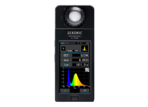
- Spectrometer
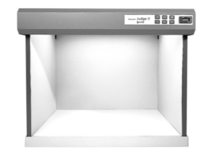
- Light box
4.3. Tuning step by step[edit | edit source]
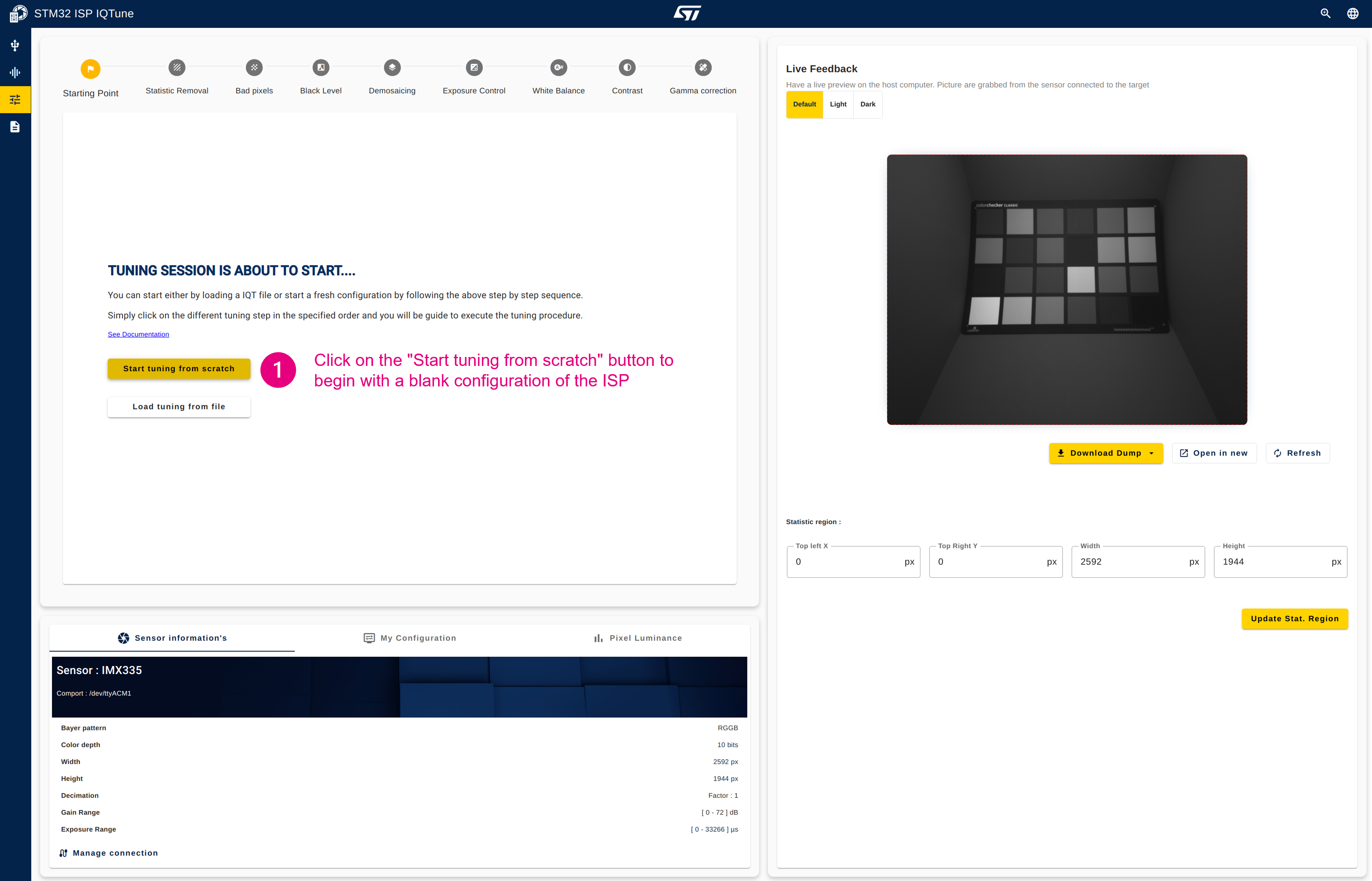
To execute the tuning procedure, start from a blank page:
- Click on the "Start tuning from scratch" button to begin with a blank configuration of the ISP.
4.3.1. Step 1: Configure the statistics removal[edit | edit source]
Description:
This module removes potential statistical data inserted by a sensor before starting the demosaicing conversion, which could be impacted by remaining statistics. It is typically used by sensors with a parallel interface, which cannot distinguish between statistics and pixel data. CSI-2 sensors typically split these flows using different virtual channel IDs.
Configuration procedure:
- Enable or disable the statistic removal module.
- When enabled, you can configure the number of first lines to skip and the number of lines to keep. These parameters depend on the sensor datasheet.
- Apply the configuration.
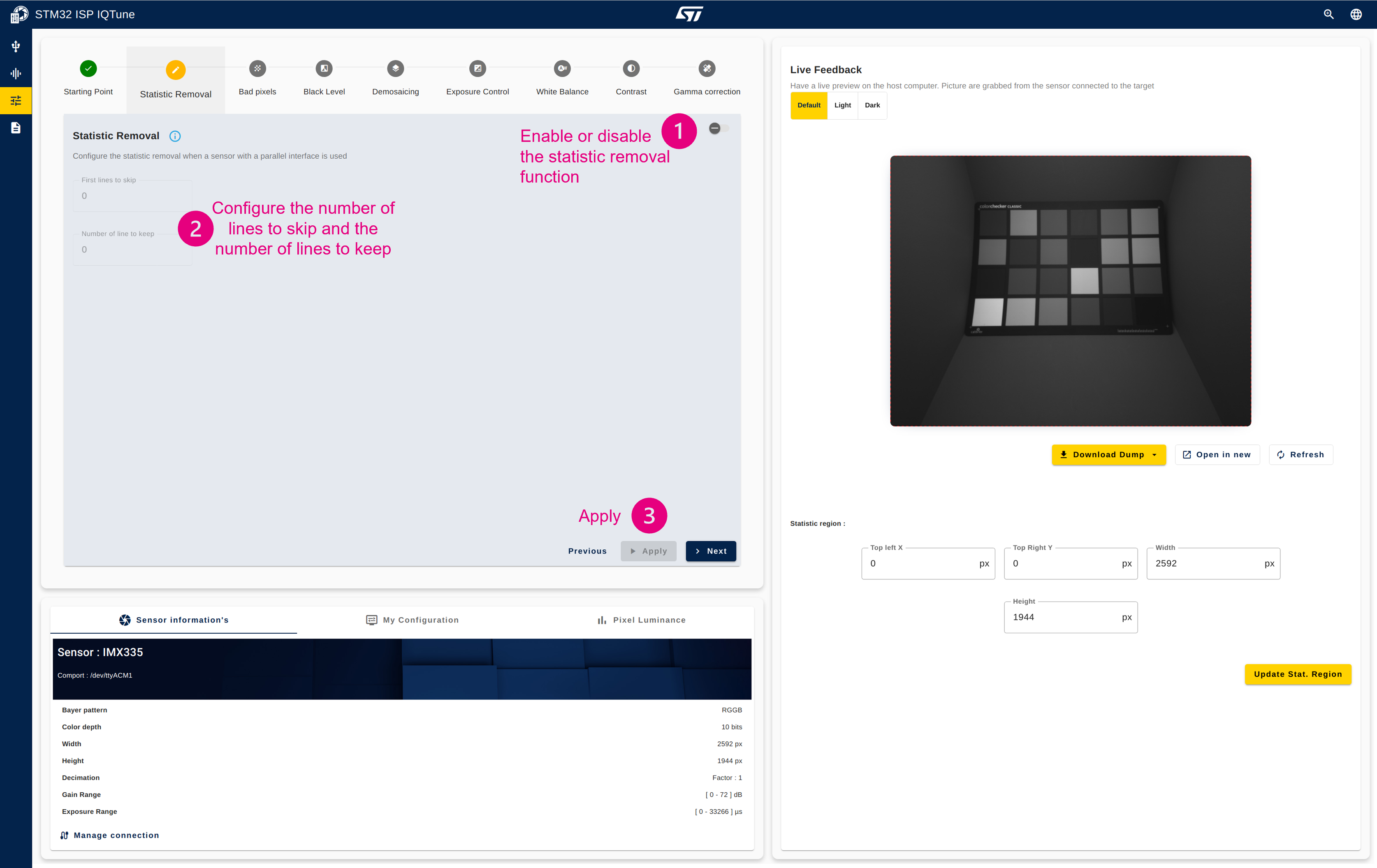
| With IMX335 sensor (this current example) the statistic removal is disabled. It is often the case with CSI2 sensor |
4.3.2. Step 2: Configure the bad pixel[edit | edit source]
Description:
This module aims to detect and correct artifacts generated by a bad pixel on the sensor array. It is based on correlation extraction, not fixed locations.
It works for RAW Bayer flows only, as RGB flows are assumed to be already cleaned.
All arriving components are scanned, and the horizontal continuity correlation versus the two left and two right neighbors, on both the local component and the adjacent RAW Bayer component, is extracted:
- If a component is considered too light, it is declared as bad.
- Components that are too dark are not extracted to avoid false positives.
If a component is assumed to be bad, it is replaced by the horizontal average of its two neighbors (with the same component).
When the module is enabled, the user can configure the strength from 0 (high tolerance) to 7 (aggressive detection). In return, the 12-bit counter reports the number of bad components corrected. The counter resets every frame.
Configuration procedure:
- Enable the bad pixel module.
- Once enabled, enable or disable the bad pixel software algorithm.
- If the bad pixel algorithm is enabled, you can configure the threshold and in return be informed of the strength selected by the algorithm and the number of bad pixels detected. If the bad pixel algorithm is disabled, you can choose a fixed strength and in return be informed of the number of bad pixels detected.
- Apply the configuration.
| The current manufacturing processes for image sensors minimize or eliminate defective pixels. Additionally, some image sensors feature automatic defective pixel correction, reducing the need for the ISP bad pixel module. We advise disabling this module if no bad pixel artifacts are detected. |
4.3.3. Step 3: Configure the black level[edit | edit source]
Description:
This module suppresses a potential positive black-level offset, which occurs when the sensor sends non-null pixels while capturing a black picture. R, G, and B component offsets are subtracted from the R, G, and B Bayer components to achieve a black picture: R = G = B = 0.
| Most of the time, the black-level offset information can be found in the datasheet of the sensor. The following procedure can be used if this information is missing or to confirm it. |
Configuration procedure:
- Enable the black level module
- Place a cap on the sensor (the preview frame is now black)
- Open in the "Pixel Luminance" panel
- Click on "Before demosaicing" to get the statistics before the demosaicing (in the RAW world)
- Click on "Recalculate stats"
- The "Average value of RGB & Luminance" graph is updated with the R, G, and B component averages that correspond to the black offset to be applied for each R, G, and B component. In this example, with the IMX335, we obtain R=12, G=12, and B=12.
- Set the R, G, and B offset values
- Apply the values by clicking the play button
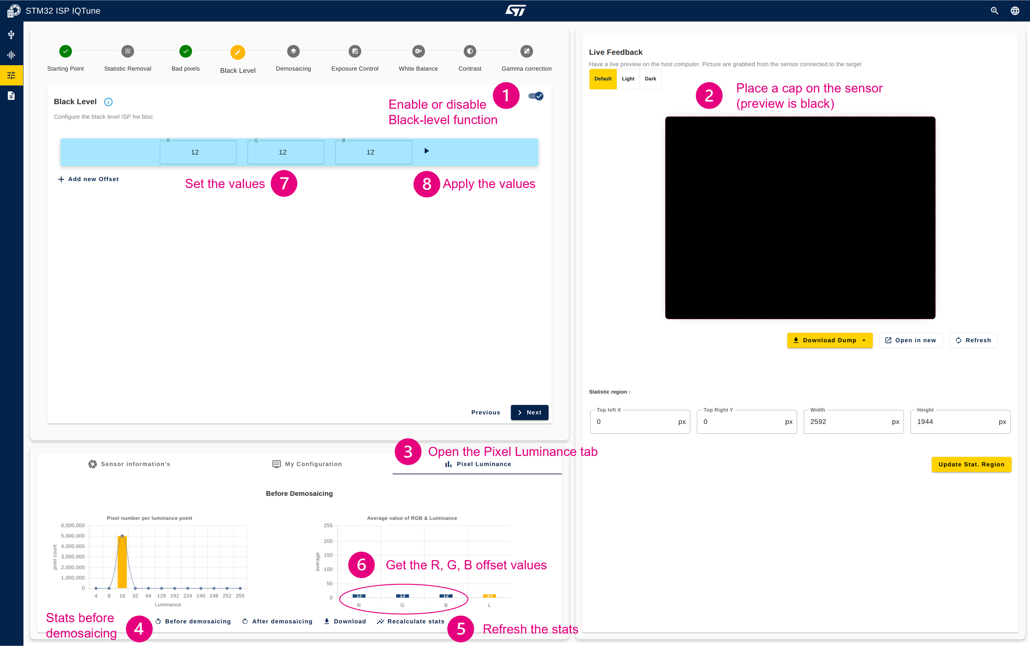
| Multiple offset values can be tested by adding a new configuration using the "Add new Offset" button. To select the configuration, click the play button. The applied configuration appears highlighted in blue.  |
4.3.4. Step 4: Configure the demosaicing[edit | edit source]
Description:
The module operates on the pixel pipes. It implements a medium-quality conversion from RAW Bayer 8 bpp to RGB 24 bpp. The output RGB pixel rate matches the input component rate.
The demosaicing process takes the surrounding 3x3 components as input, applies linear heuristics to determine the most likely missing components, and generates an output RGB888 pixel. The underlying heuristic filters try to extract and adapt to edges, horizontal and vertical lines, and lone pixels (0: no detection, pure linear interpolation; 1 to 7: relative detection strength).
Configuration procedure:
- Enable the demosaicing module.
- Once enabled, you can update the strength of the filters used to detect edges, horizontal and vertical lines, and lone pixels. The default values provide good results.
- Apply the configuration.
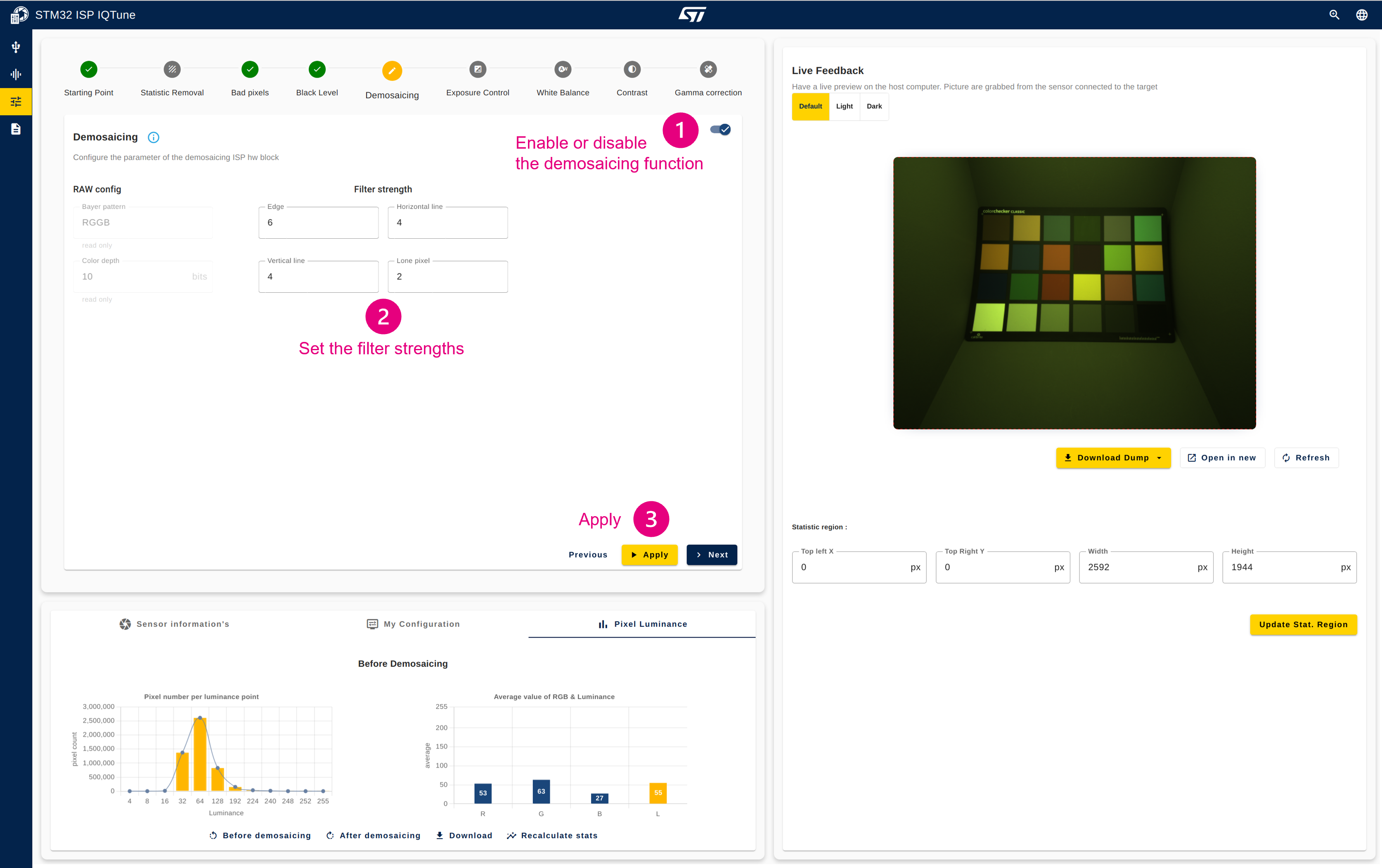
| The demosaicing "RAW config", "Bayer pattern", and "Color depth" are retrieved from the sensor information and are automatically set. If one of the parameters is incorrect, it is likely that the sensor driver does not provide the correct information. |
4.3.5. Step 5: Configure the gamma correction[edit | edit source]
Description:
This module implements a gamma compression on each R, G, and B component using a static gamma exponent of 2.2 to store gamma-compressed pictures, as defined in the sRGB standard.
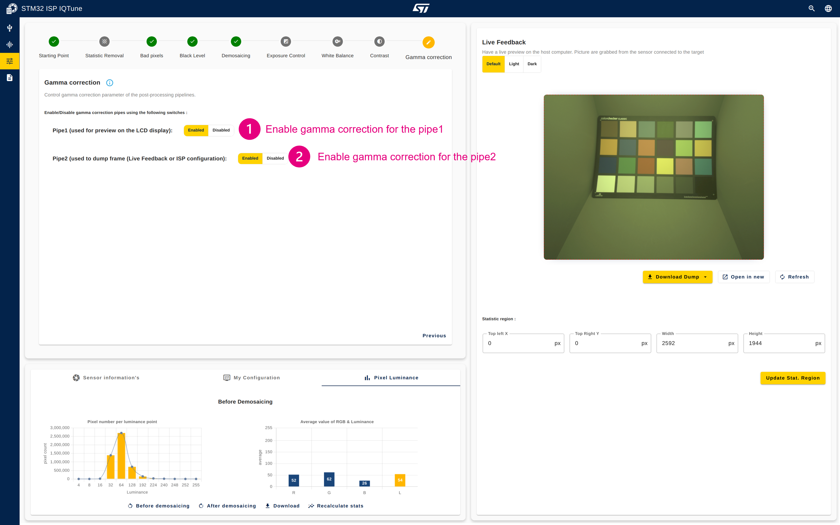
| To achieve good color rendering while dumping the buffer, it is important to enable gamma on both pipe1 and pipe2. |
Configuration procedure:
- Enable unique gamma correction setting for both pipe1 and pipe2
4.3.6. Step 6: Configure the exposure control[edit | edit source]
Description:
This module aims to configure the sensor exposure to ensure the frame is well-exposed (neither too dark nor too bright). The exposure is not controlled by a parameter inside the ISP but by the sensor itself by updating the exposure time or the sensor gain, or both.
The user has the possibility to:
- Control the exposure manually by updating the gain or the exposure time, or both
- Enable the auto exposure algorithm
- The algorithm automatically sets the appropriate sensor gain and exposure time based on statistics retrieved by the ISP and the ideal exposure target.
- In this configuration, the user can control only the exposure compensation to shift the exposure target value.
- Configure the sensor delay parameter
| The exposure compensation is expressed in exposure value (EV). +1EV doubles the exposure target |
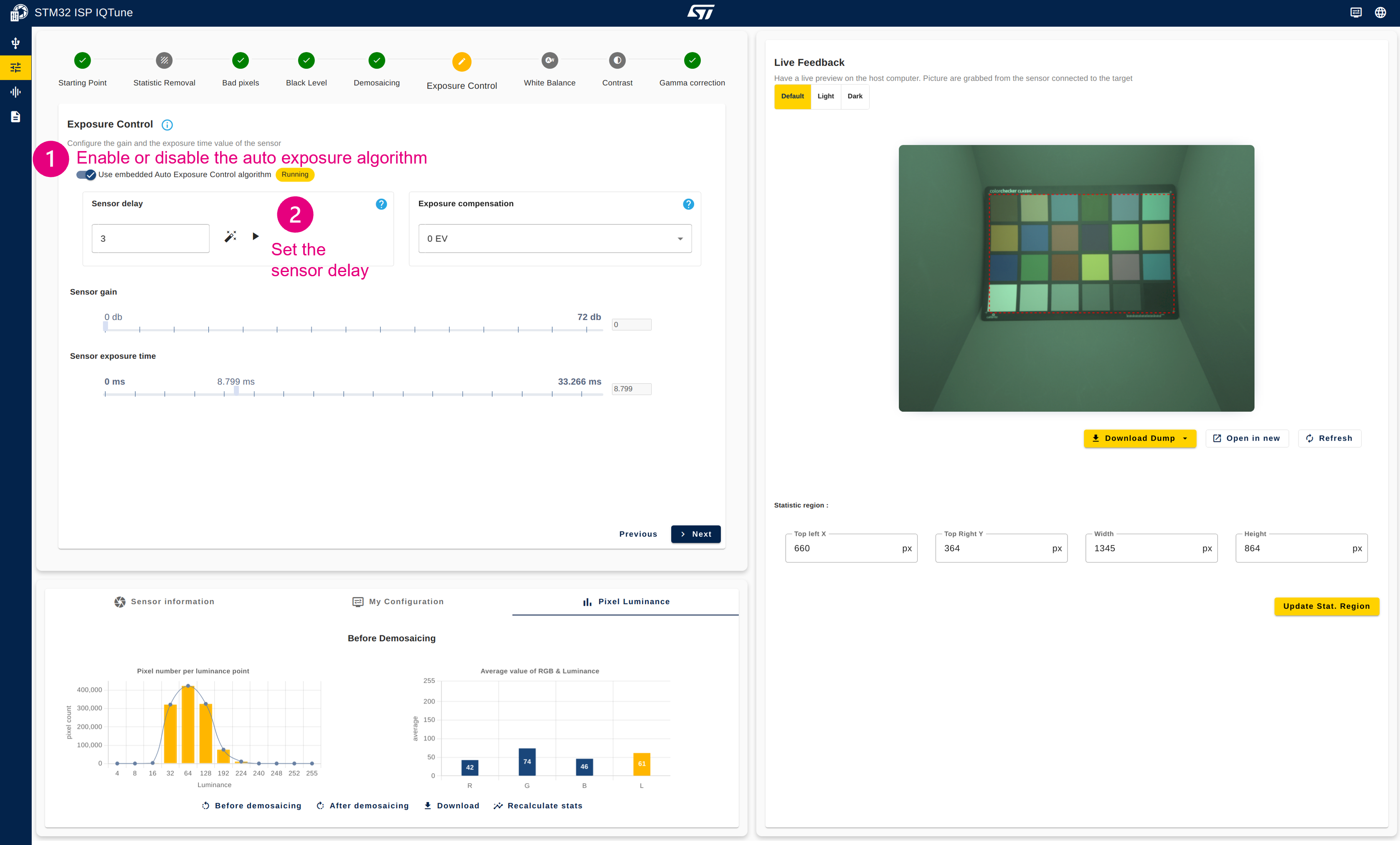
| The sensor delay is the the number of frame needed by the sensor to reflect the sensor gain/exposure configuration. It can be set manually or can be automatically computed using the magic wand. |
Configuration procedure:
- Enable the auto exposure algorithm
- If sensor delay feature is displayed, click on the magic wand to compute the sensor delay
| The auto exposure will adapt the sensor gain and exposure values during the auto white balance profile calibration |
4.3.7. Step 7: Configure auto white balance (AWB) profiles[edit | edit source]
In the following description of the AWB profile configuration, a white balance profile for a given illuminant refers to a combination of two sets of parameters: the ISP gains associated with a color correction matrix (CCM).
 |
Description:
This module interacts with the ISP gains and the color correction matrix block:
- The ISP gain equalizes the R, G, and B components by applying independent gains to each R, G, and B component to ensure white appears white.
- The color correction matrix converts the frame from the sensor RGB space to the sRGB space to achieve good color rendering.
Configuration procedure:
4.3.7.1. Prepare your white balance profile[edit | edit source]
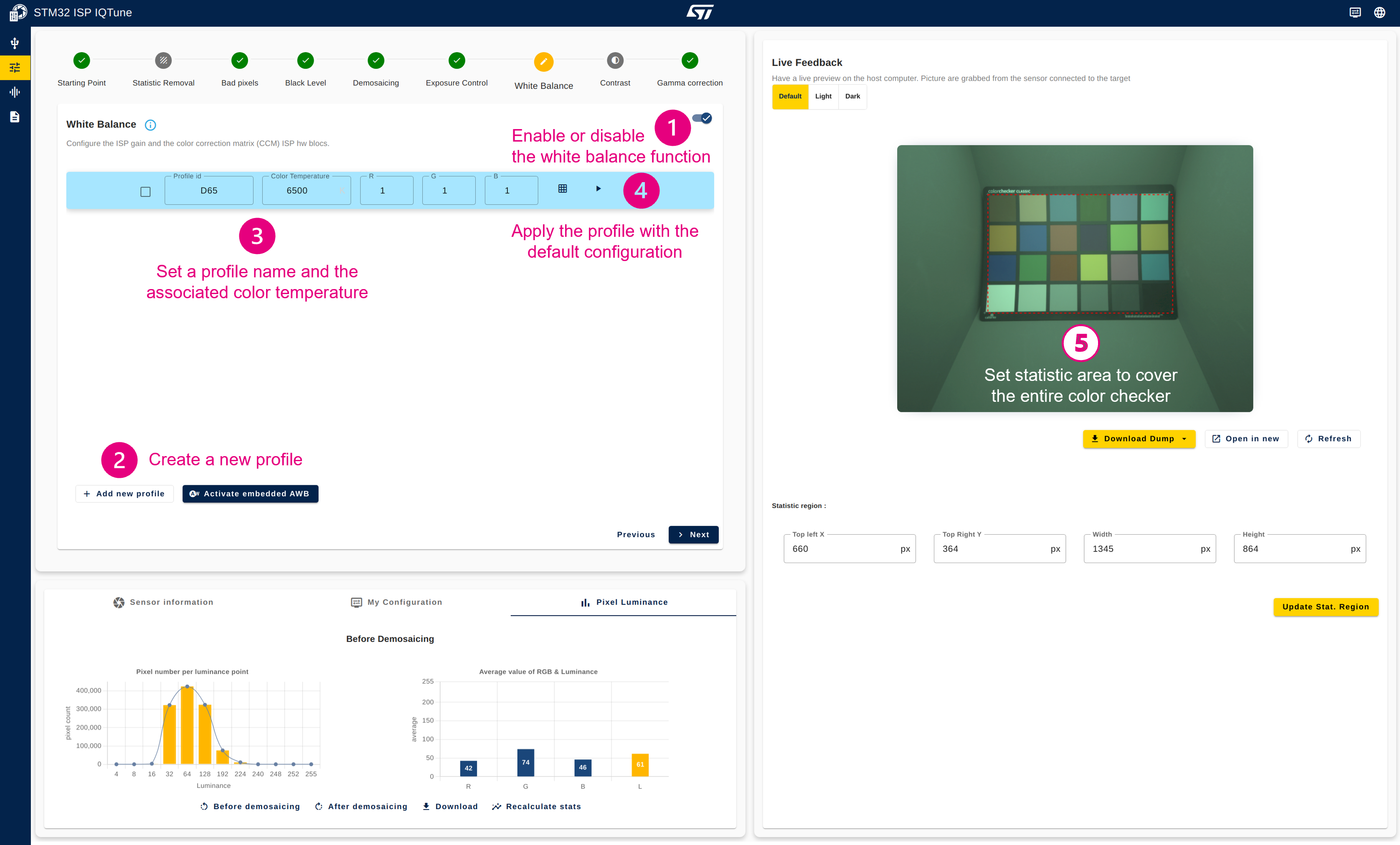
- Enable the white balance correction module.
- Ensure that the AWB algorithm is disabled.
- Create a new white balance profile. Newly created profiles always have all gains set to 1 and a CCM set with an identity matrix.
- Name your profile and set the color temperature information box with the value retrieved using the spectrometer.
- Apply the white balance profile.
- Set the statistics area to cover the entire color checker.
| To configure the statistics area, click on the Live Feedback picture and drag the mouse to draw the statistics area. The statistics region coordinates are then updated and the red dashed rectangle is displayed on the Live Feedback picture as well as on the preview in the LCD display. The color of the statistics area can be changed by clicking on the button above the Live Feedback picture. Possible values are: Default, Light, or Dark. |
4.3.7.2. Configure the ISP gain to ensure white appears white[edit | edit source]
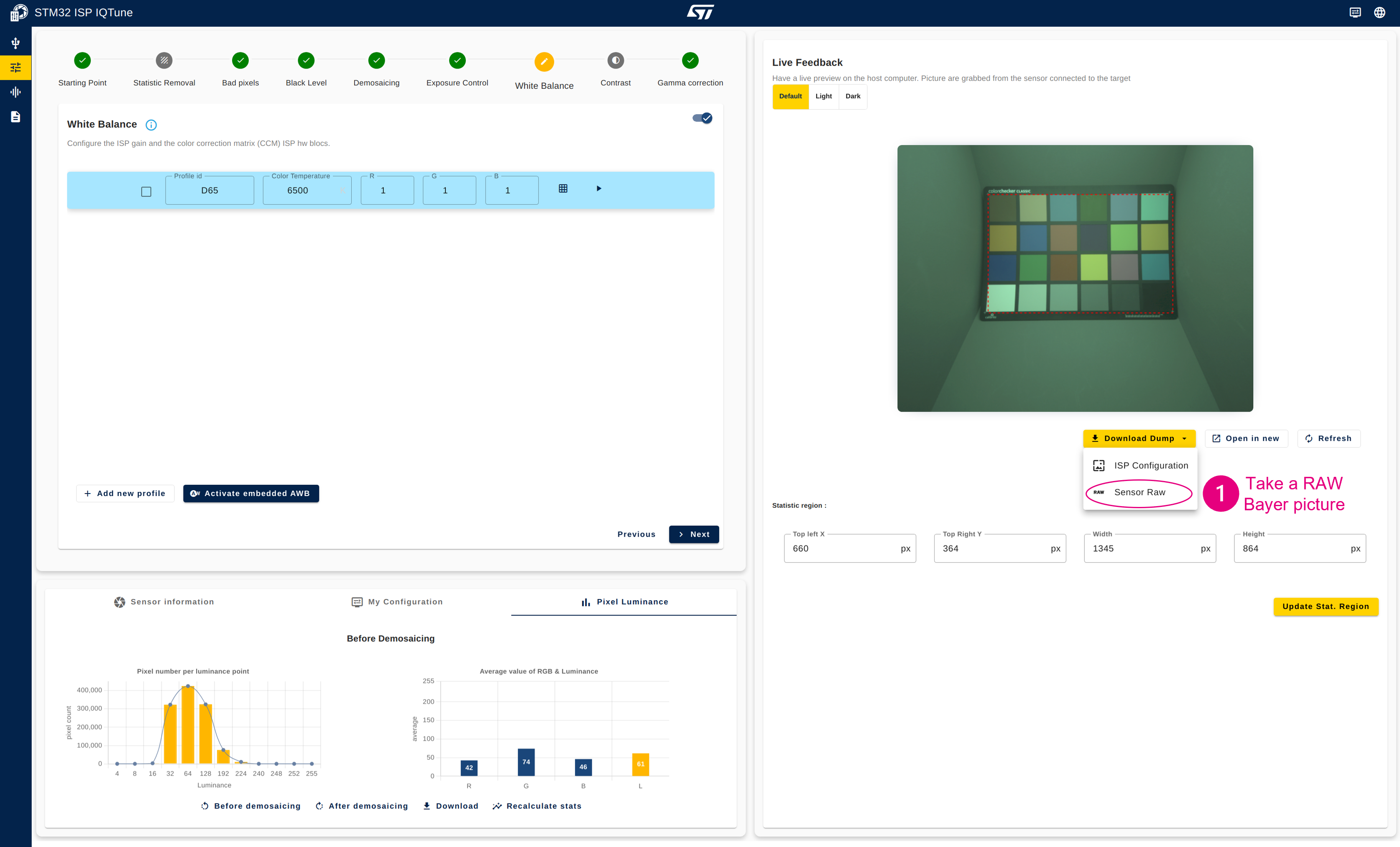
- Take a RAW Bayer picture of the color checker (picture is saved as a .pgm file).
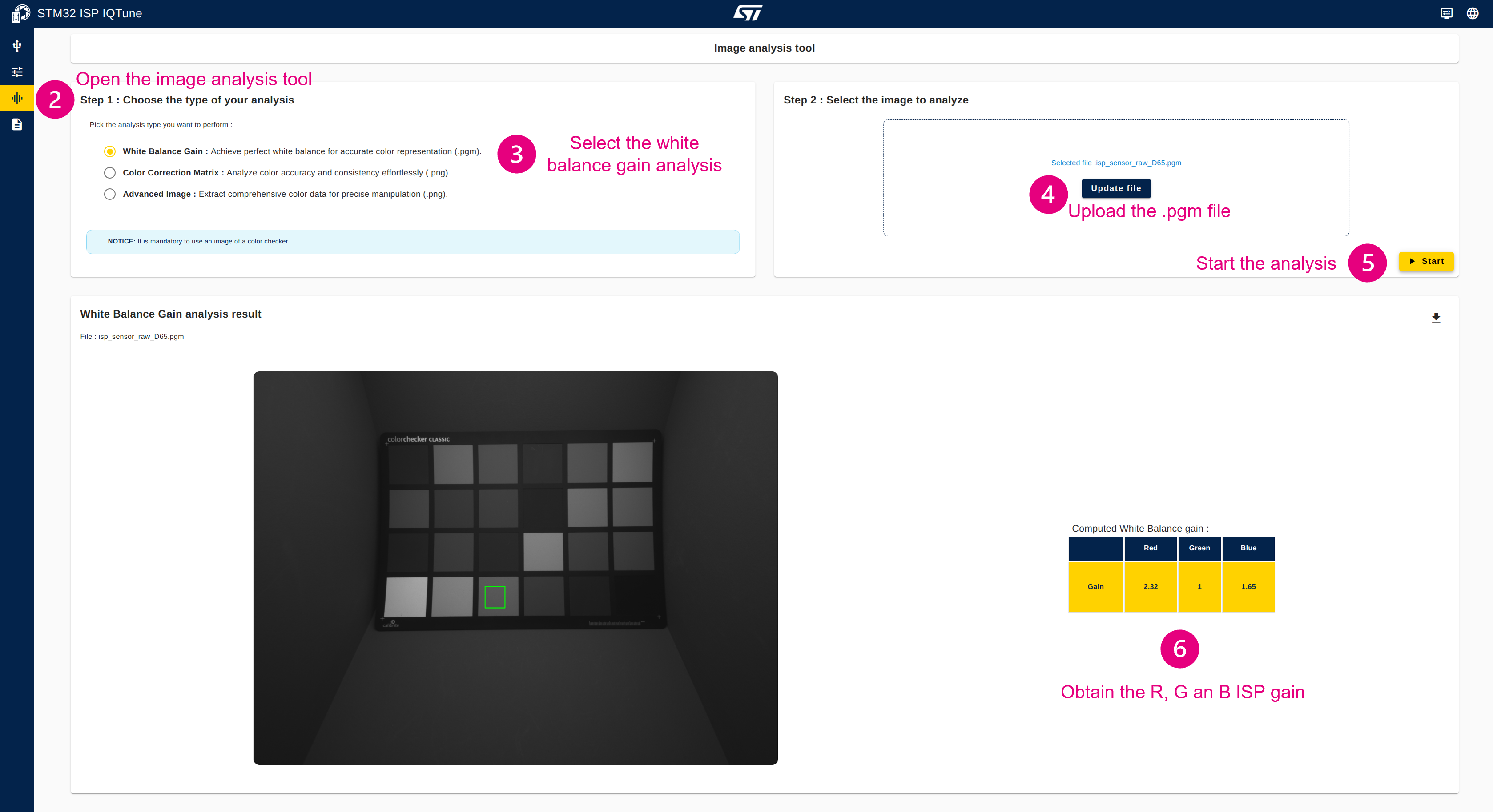
- Open the "Analysis" panel.
- Select the "Color Checker Type".
In case you are using a custom color checker, select Custom Color Checker Type and upload patch references from a JSON file using the following template:
cc24_custom_values_template.json{ "colorCheckerName": "Custom ColorChecker", "colorCheckerPatches": [ { "patchNumber": 1, "colorName": "Dark Skin", "Lab": { "L": 37.986, "a": 13.555, "b": 14.059 } }, { "patchNumber": 2, "colorName": "Light Skin", "Lab": { "L": 65.711, "a": 18.13, "b": 17.81 } }, { "patchNumber": 3, "colorName": "Blue Sky", "Lab": { "L": 49.927, "a": -4.88, "b": -21.925 } }, { "patchNumber": 4, "colorName": "Foliage", "Lab": { "L": 43.139, "a": -13.095, "b": 21.905 } }, { "patchNumber": 5, "colorName": "Blue Flower", "Lab": { "L": 55.112, "a": 8.844, "b": -25.399 } }, { "patchNumber": 6, "colorName": "Bluish Green", "Lab": { "L": 70.719, "a": -33.397, "b": -0.199 } }, { "patchNumber": 7, "colorName": "Orange", "Lab": { "L": 62.661, "a": 36.067, "b": 57.096 } }, { "patchNumber": 8, "colorName": "Purplish Blue", "Lab": { "L": 40.02, "a": 10.41, "b": -45.964 } }, { "patchNumber": 9, "colorName": "Moderate Red", "Lab": { "L": 51.124, "a": 48.239, "b": 16.248 } }, { "patchNumber": 10, "colorName": "Purple", "Lab": { "L": 30.325, "a": 22.976, "b": -21.587 } }, { "patchNumber": 11, "colorName": "Yellow Green", "Lab": { "L": 72.532, "a": -23.709, "b": 57.255 } }, { "patchNumber": 12, "colorName": "Orange Yellow", "Lab": { "L": 71.941, "a": 19.363, "b": 67.857 } }, { "patchNumber": 13, "colorName": "Blue", "Lab": { "L": 28.778, "a": 14.179, "b": -50.297 } }, { "patchNumber": 14, "colorName": "Green", "Lab": { "L": 55.261, "a": -38.342, "b": 31.37 } }, { "patchNumber": 15, "colorName": "Red", "Lab": { "L": 42.101, "a": 53.378, "b": 28.19 } }, { "patchNumber": 16, "colorName": "Yellow", "Lab": { "L": 81.733, "a": 4.039, "b": 79.819 } }, { "patchNumber": 17, "colorName": "Magenta", "Lab": { "L": 51.935, "a": 49.986, "b": -14.574 } }, { "patchNumber": 18, "colorName": "Cyan", "Lab": { "L": 51.038, "a": -28.631, "b": -28.638 } }, { "patchNumber": 19, "colorName": "White", "Lab": { "L": 96.539, "a": -0.425, "b": 1.186 } }, { "patchNumber": 20, "colorName": "Neutral 8", "Lab": { "L": 81.257, "a": -0.638, "b": -0.335 } }, { "patchNumber": 21, "colorName": "Neutral 6.5", "Lab": { "L": 66.766, "a": -0.734, "b": -0.504 } }, { "patchNumber": 22, "colorName": "Neutral 5", "Lab": { "L": 50.867, "a": -0.153, "b": -0.27 } }, { "patchNumber": 23, "colorName": "Neutral 3.5", "Lab": { "L": 35.656, "a": -0.421, "b": -1.231 } }, { "patchNumber": 24, "colorName": "Black", "Lab": { "L": 20.461, "a": -0.079, "b": -0.973 } } ] }
- Select "White Balance Gain" analysis.
- Upload the RAW Bayer picture (.pgm file).
- Start the white balance gain analysis. If the analysis fails, it is likely that the color checker is not detected because it is underexposed. In that case, slightly update the sensor exposure time and perform the steps again from step 1.
- Get the R, G, and B ISP gains computed by the analysis tool.
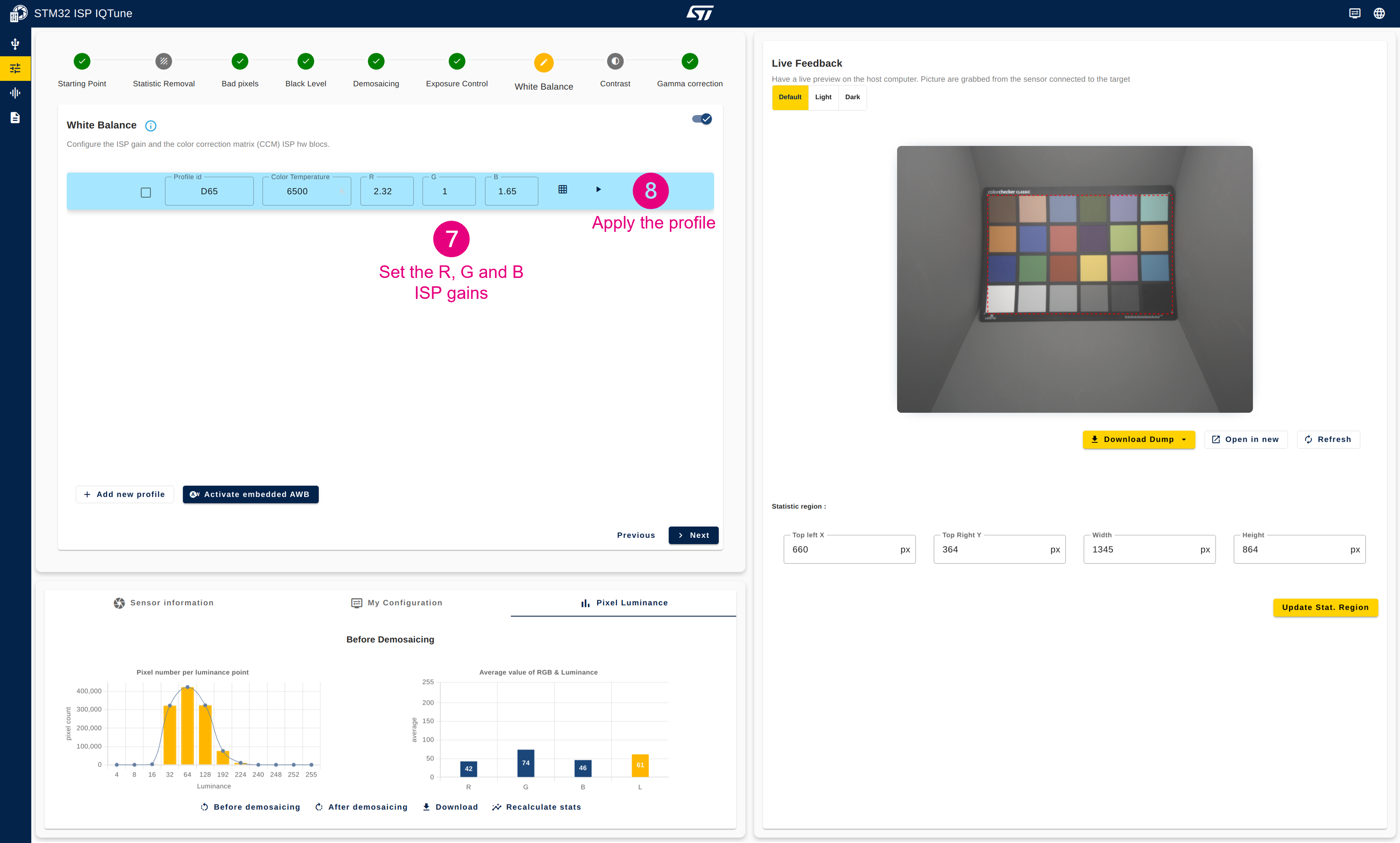
- Go back to the "White Balance" panel and set the R, G, and B gains of your white balance profile.
- Apply the white balance profile.
4.3.7.3. Configure the color correction matrix for optimal color rendering[edit | edit source]
- Take an RGB picture of the color checker with ISP gain applied (frame is saved as a .png file).
- Open the "Analysis" panel.
- Select "Color Correction Matrix" analysis.
- Upload the RGB picture (.png file)
- Start the CCM analysis.
- Get the CCM coefficient that have been computed (you can use the copy button to save those values).
- Go back to the "White Balance" panel and set the CCM coefficients (you can paste the coefficient values that have been copied)
- Apply the white balance profile.
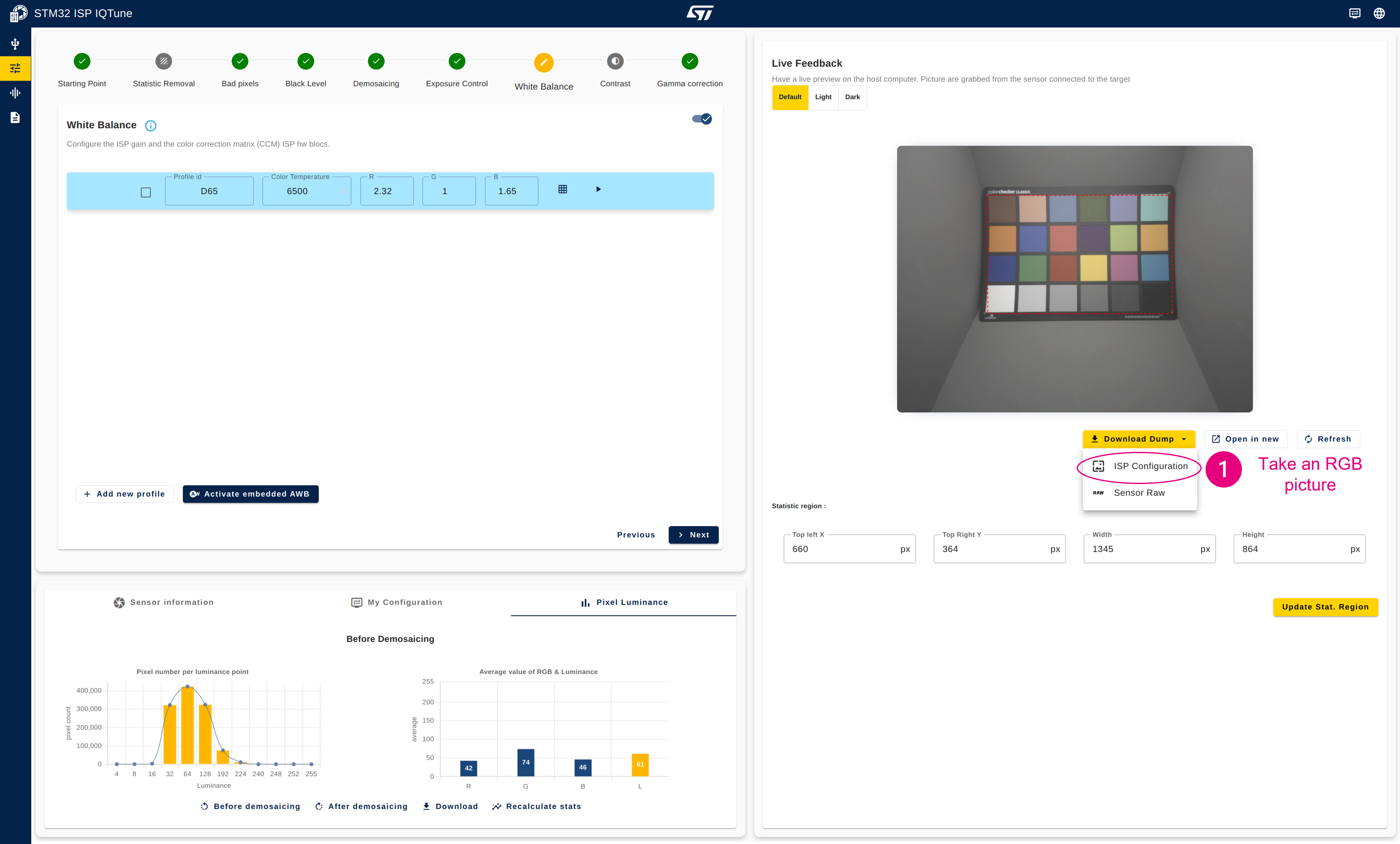
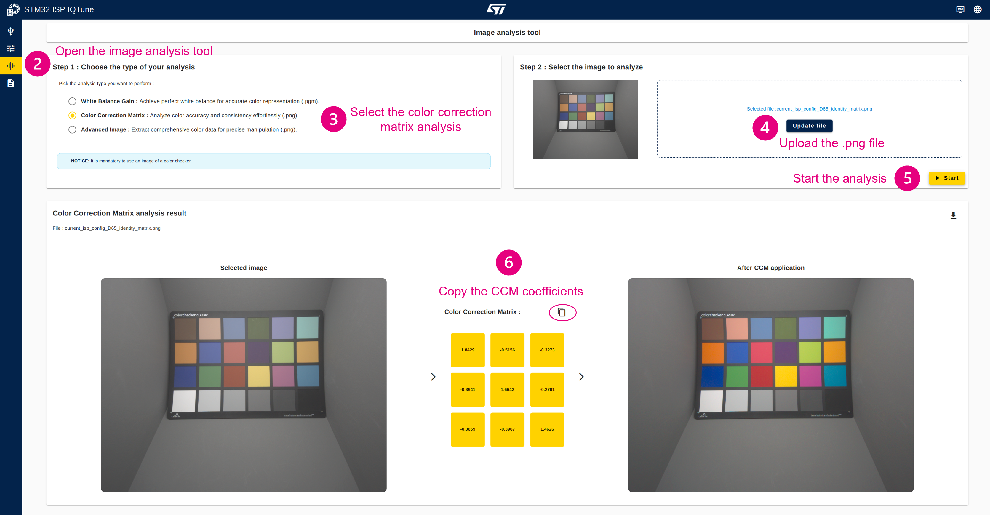
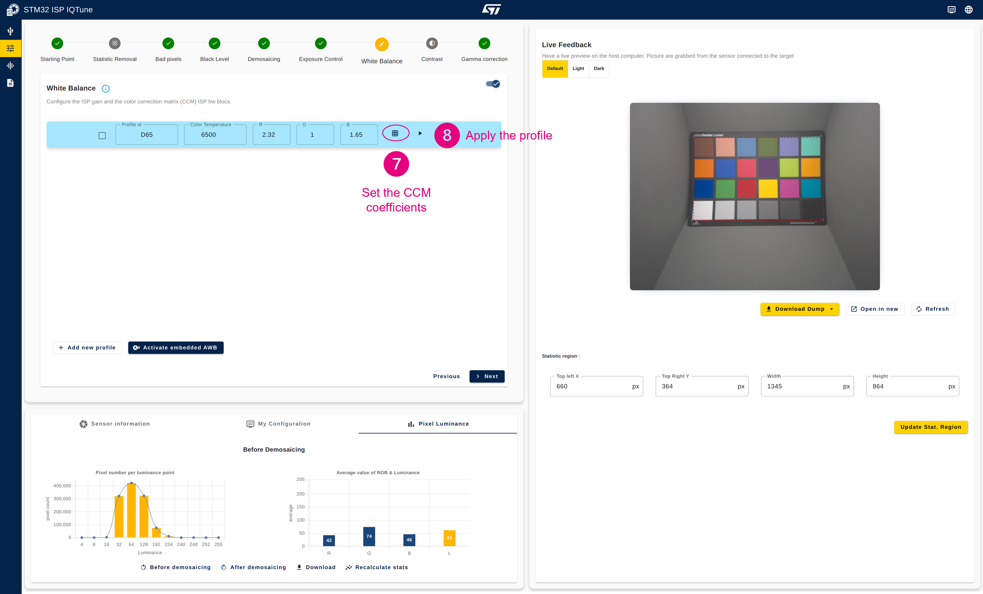

| At this stage, the color rendering for the selected illuminant is close to the reference. |
4.3.7.4. Analyze the final ISP configuration to check color accuracy versus the reference colors[edit | edit source]
- Take an RGB picture of the color checker with ISP gain and CCM applied (frame is saved as a .png file).
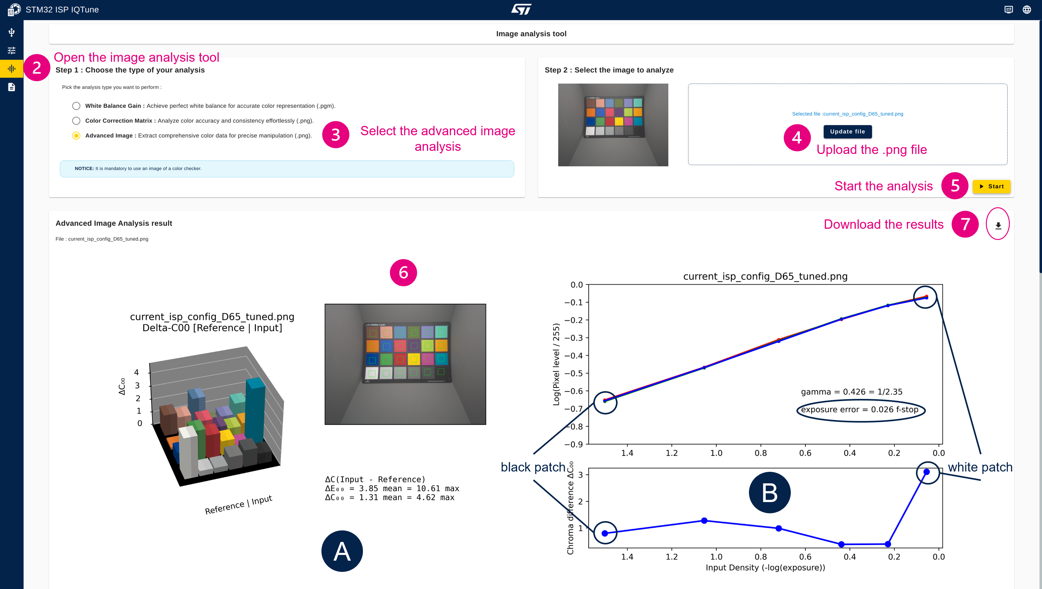
- Open the "Analysis" panel.
- Select "Advanced Image" analysis.
- Upload the RGB picture (.png file).
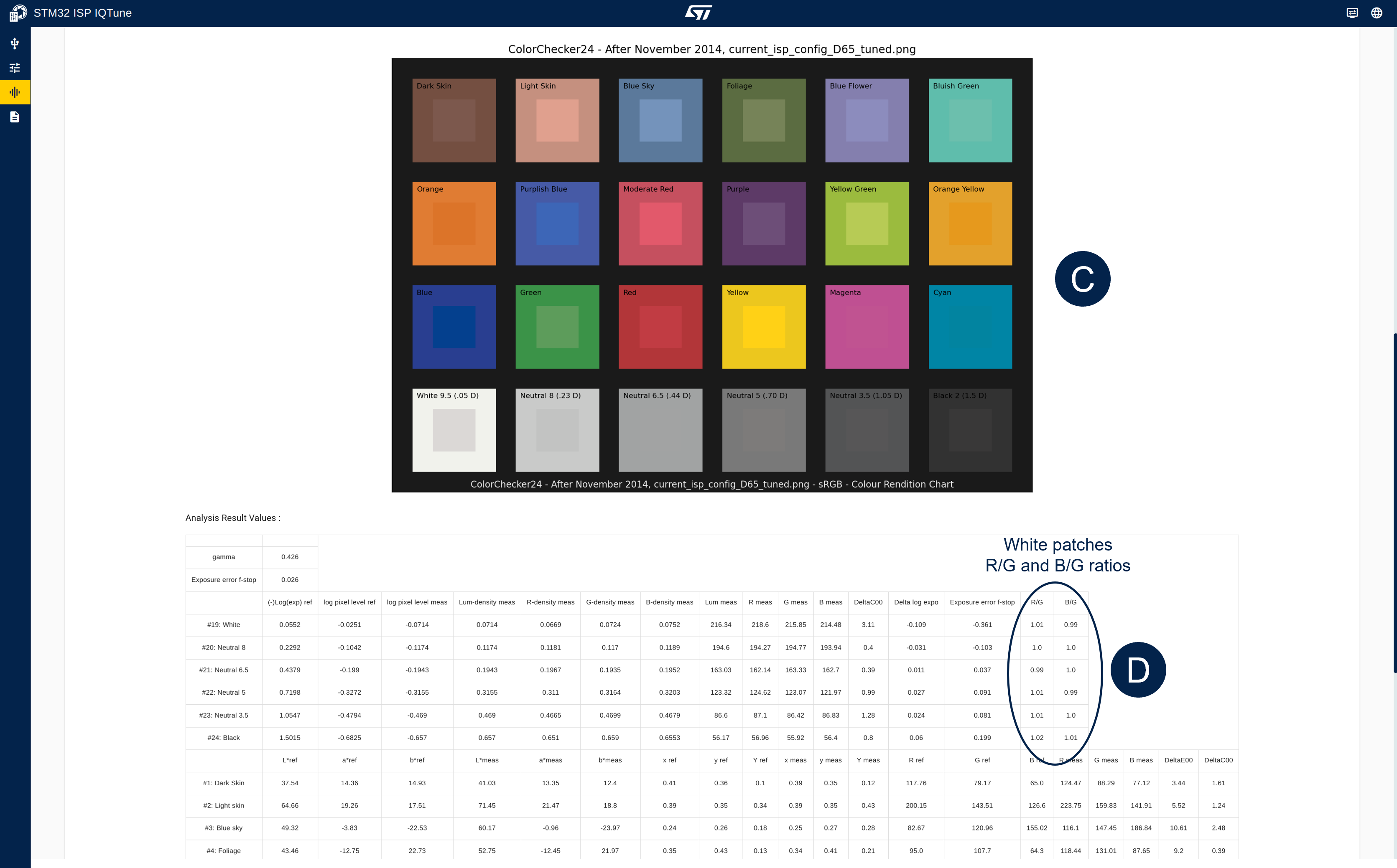
- Start the advanced image analysis.
- The color analysis is complete, and you can verify the color accuracy with the different graph and information provided.
- Optionally, you can download the analysis results as a zip file containing the graphs and .csv file.
|
The color analysis provides information and metrics on how the colors are rendered according to the ISP configuration:
|
4.3.7.5. Enable the AWB algorithm[edit | edit source]
- Select the white balance profile to be managed by the AWB algorithm.
- Activate the AWB algorithm.
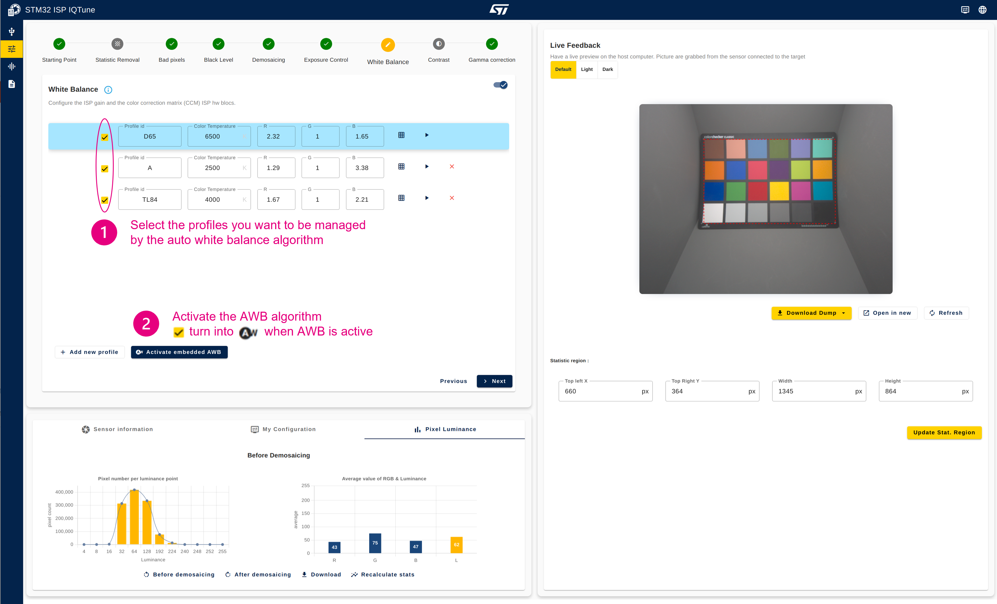
The yellow tick box turns into the AWB logo when AWB is active. When AWB is active, the profile selected by the AWB algorithm is highlighted in blue.
 |
4.3.8. Step 8: Configure the contrast (optional)[edit | edit source]
Description:
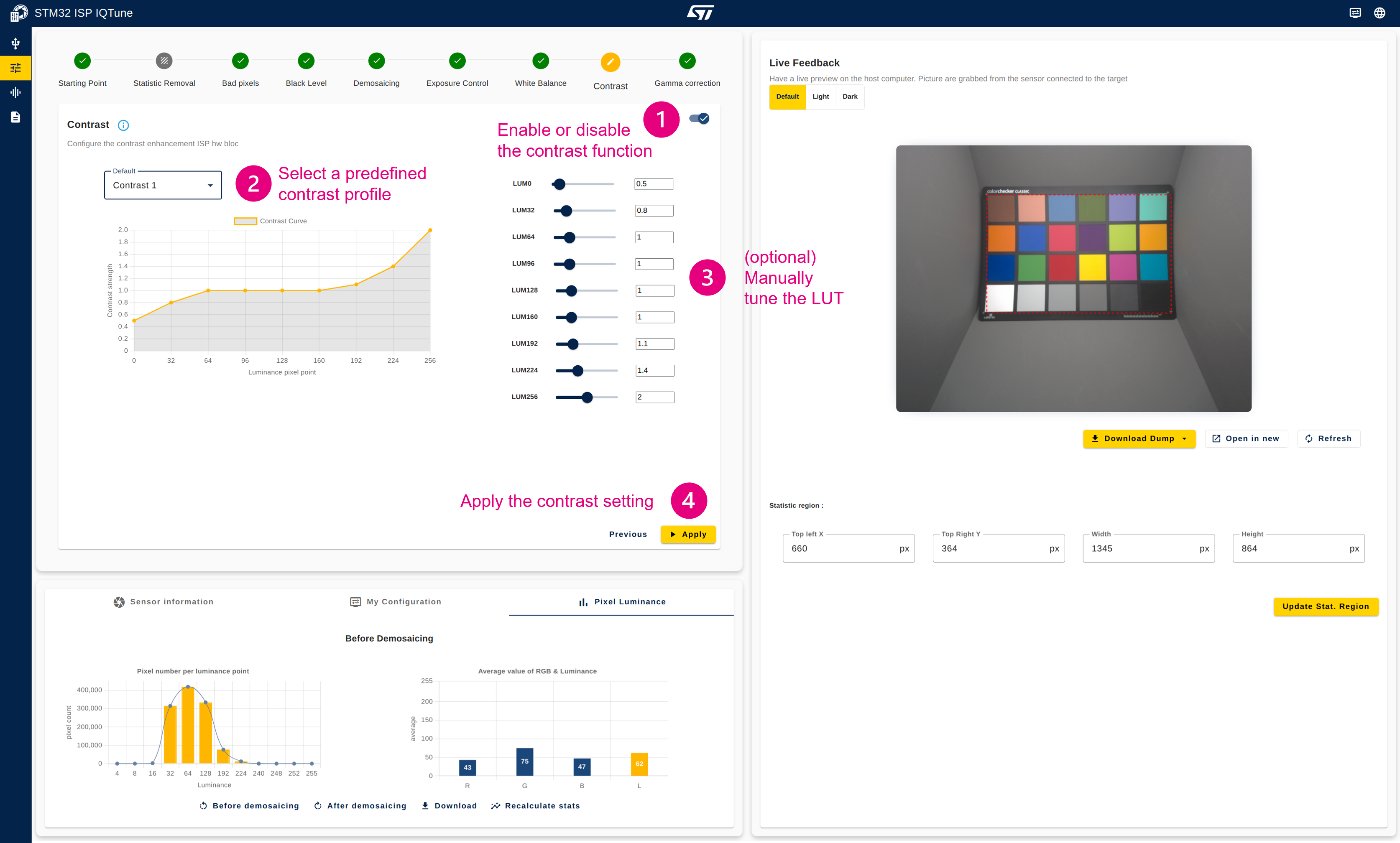
This module concludes the image processing pipeline. It enhances the contrast of the frame by non-linear emphasis of pixel luminance. It takes the RGB values from the pipeline, computes the luminance of the local pixel, and determines the desired luminance adjustment factor based on the input luminance using a lookup table. The output RGB components are clamped to 8 bits.
Configuration procedure:
- Enable the contrast module
- Select a predefined contrast profile
- Optionally tune the LUT
- Apply the contrast settings
4.3.9. Step 9: Export the ISP configuration[edit | edit source]
Description:
Once the ISP tuning is finalized, the ISP configuration needs to be exported so that the ISP settings and behaviors are reflected in the final application.
Configuration procedure:
- Open the "My Configuration" panel
- Click on "Export Configuration" and chose the export format suitable for your project:
- For a Linux project, you need to export the ISP configuration as a .yaml file.
- For a bare-metal MCU project, you need to export the ISP configuration as a .h code file.

| Linux: The generated .yaml file must be uploaded to the target in the following directory: scp <sensor .yaml file> root@<IP address of the platform>:/usr/share/libcamera/ipa/dcmipp/ The selection of the .yaml file is done at runtime based on the name of the detected sensor. If the name of the detected sensor is imx335, then the imx335.yaml file is loaded by libcamera to set the ISP configuration created by the user. |
| Bare-metal MCU: The isp_param_conf.h generated file must be copied in the application project to take into account the ISP configuration created by the user. |
4.4. Tips[edit | edit source]
4.4.1. Save and load your current work[edit | edit source]

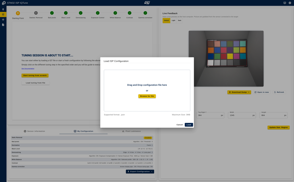
4.4.2. Load a saved work[edit | edit source]
4.4.3. Sensor information at a glance[edit | edit source]
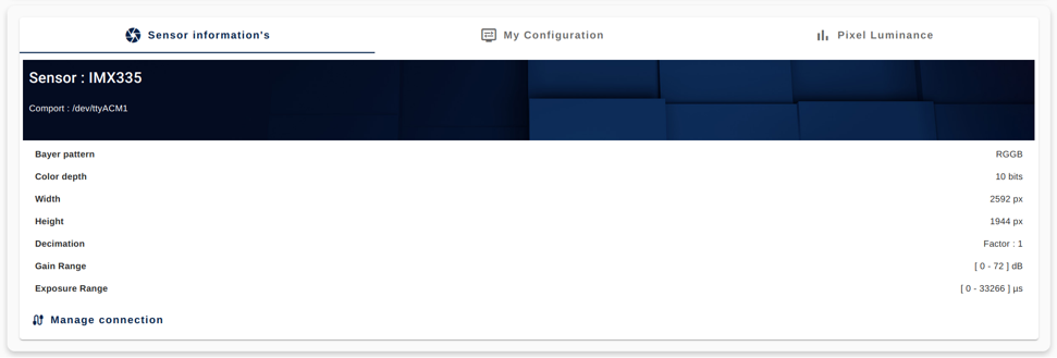
All the sensor information is summarized in the "Sensor Information" panel.
4.4.4. Current configuration at a glance[edit | edit source]
All ISP module status is summarized in the "My Configuration" panel.


