Template:ArticleMainWriter Template:ArticleApprovedVersion
SUMMARY
This article lists all internal peripherals embedded in STM32MP15 device and shows the assignment possibilities to the runtime contexts for each one of them.
Via this article, you can also access to individual peripheral articles in which information related to the overview and configuration can be found.
1. Internal peripherals overview[edit | edit source]
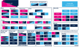
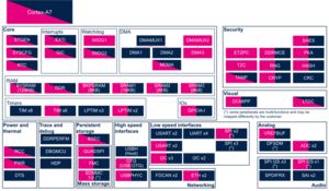
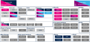
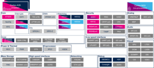
The figure below shows all peripherals embedded in STM32MP15 device, grouped per functional domains that are reused in many places of this wiki to structure the articles.
Several runtime contexts exist on STM32MP15 device[1], corresponding to the different Arm cores and associated security modes:
- Arm dual core Cortex-A7 secure (Trustzone), running a Secure Monitor or Secure OS like OP-TEE
- Arm dual core Cortex-A7 non secure , running Linux
- Arm Cortex-M4 (non-secure), running STM32Cube
Some peripherals can be strictly assigned to one runtime context: this is the case for most of the peripherals, like USART or I2C.
Other ones can be shared between several runtime contexts: this is the case for system peripherals, like PWR or RCC.
The legend below shows how assigned and shared peripherals are identified in the assignment diagram that follows:

Both the diagram below and the following summary table (in Internal peripherals assignment chapter below) are clickable in order to jump to each peripheral overview articles and get more detailed information (like software frameworks used to control them). They list STMicroelectronics recommendations. The STM32MP15 reference manual [2] may expose more possibilities than what is shown here.

2. Internal peripherals assignment[edit | edit source]
Internal peripherals assignment table template
Information about the "ADC internal peripheral" depends on the microprocessor device.
Several articles are created to manage STM32 MPU diversity and provide the appropriate level of information. Browse the one corresponding to the STM32 MPU you use.
| STM32 MPU devices | Associated articles |
|---|---|
| STM32MP13x lines |
STM32MP13 ADC internal peripheral |
| STM32MP15x lines |
STM32MP15 ADC internal peripheral |
| STM32MP2 series | STM32MP2 ADC internal peripheral |
3. Article purpose[edit | edit source]
The purpose of this article is to:
- briefly introduce the DAC peripheral and its main features,
- indicate the peripheral instances assignment at boot time and their assignment at runtime (including whether instances can be allocated to secure contexts),
- list the software frameworks and drivers managing the peripheral,
- explain how to configure the peripheral.
4. Peripheral overview[edit | edit source]
The DAC peripheral is a voltage output digital-to-analog converter:
- It may be configured in 8- or 12-bit mode (data could be left- or right-aligned)
- It has two output channels, each with its own converter
- The dual DAC channel mode could be done independently or simultaneously
- It has built-in noise and triangle waveform generator and supports triggers for conversions, using: TIM[3], LPTIM[4] or EXTI[5]
- The DAC output buffer allows a high drive output current
- It can operate under Normal mode or low-power Sample and Hold mode (uses LSI clock, from RCC[6]).
- It may be used in conjunction with the DMA[7] controller (with underrun error detection)
- The common reference voltage, can be provided by either VREFBUF[8] or any other external regulator[9] wired to VREF+ pin.
Refer to the STM32MP15 reference manuals for the complete list of features, and to the software frameworks and drivers, introduced below, to see which features are implemented.
5. Peripheral usage[edit | edit source]
This chapter is applicable in the scope of the OpenSTLinux BSP running on the Arm® Cortex®-A processor(s), and the STM32CubeMPU Package running on the Arm® Cortex®-M processor.
5.1. Boot time assignment[edit | edit source]
The DAC peripheral is not used at boot time.
5.2. Runtime assignment[edit | edit source]
5.2.1. On STM32MP15x lines  [edit | edit source]
Click on ![]() to expand or collapse the legend...
to expand or collapse the legend...
| Domain | Peripheral | Runtime allocation | Comment | |||
|---|---|---|---|---|---|---|
| Instance | Cortex-A7 secure (OP-TEE) |
Cortex-A7 nonsecure (Linux) |
Cortex-M4 (STM32Cube) | |||
| Analog | DAC | DAC | ☐ | ☐ | Assignment (single choice) | |
6. Software frameworks and drivers[edit | edit source]
Below are listed the software frameworks and drivers managing the DAC peripheral for the embedded software components listed in the above tables.
- Linux®: IIO framework
- STM32Cube: HAL DAC driver
7. How to assign and configure the peripheral[edit | edit source]
The peripheral assignment can be done via the STM32CubeMX graphical tool (and manually completed if needed).
This tool also helps to configure the peripheral:
- partial device trees (pin control and clock tree) generation for the OpenSTLinux software components,
- HAL initialization code generation for the STM32CubeMPU Package.
The configuration is applied by the firmware running in the context in which the peripheral is assigned.
For the Linux kernel configuration, please refer to DAC device tree configuration and DAC Linux driver articles.
8. References[edit | edit source]
9. Article purpose[edit | edit source]
The purpose of this article is to:
- briefly introduce the DFSDM peripheral and its main features,
- indicate the peripheral instances assignment at boot time and their assignment at runtime (including whether instances can be allocated to secure contexts),
- list the software frameworks and drivers managing the peripheral,
- explain how to configure the peripheral.
10. Peripheral overview[edit | edit source]
The DFSDM (Digital Filter for Sigma-Delta Modulator) peripheral is used as a generic ADC. It benefits from external analog frontend interfaces and internal digital filters.
It can be used in various applications[1] such as: audio record with MEMS microphones, energy measurement with STPMS2[2] for electricity meters or motor control...
The DFSDM peripheral provides several features, among which:
- Serial or parallel input channels:
- Digital filters, that offers up to 24-bit final ADC resolution
- Conversions that can be launched continuously, or using various triggers: by software, TIM[5], LPTIM[6], EXTI[7] or synchronously with DFSDM filter 0
- Event detectors: analog watchdog high/low thresholds, short-circuit detector, extremes detector
- Break generation to TIM[5] on analog watchdog or short-circuit detector events
| DFSDM features | Number of channels | Number of filters |
|---|---|---|
| STM32MP13x lines |
4 | 2 |
| STM32MP15x lines |
8 | 6 |
Refer to the STM32 MPU reference manuals for the complete list of features, and to the software frameworks and drivers, introduced below, to see which features are implemented.
11. Peripheral usage[edit | edit source]
This chapter is applicable in the scope of the OpenSTLinux BSP running on the Arm® Cortex®-A processor(s), and the STM32CubeMPU Package running on the Arm® Cortex®-M processor.
11.1. Boot time assignment[edit | edit source]
The DFSDM peripheral is not used at boot time.
11.2. Runtime assignment[edit | edit source]
11.2.1. On STM32MP13x lines [edit | edit source]
Click on ![]() to expand or collapse the legend...
to expand or collapse the legend...
| Domain | Peripheral | Runtime allocation | Comment | ||
|---|---|---|---|---|---|
| Instance | Cortex-A7 secure (OP-TEE) |
Cortex-A7 nonsecure (Linux) | |||
| Analog | DFSDM | DFSDM | ☐ | Assignment (single choice) | |
11.2.2. On STM32MP15x lines [edit | edit source]
Click on ![]() to expand or collapse the legend...
to expand or collapse the legend...
| Domain | Peripheral | Runtime allocation | Comment | |||
|---|---|---|---|---|---|---|
| Instance | Cortex-A7 secure (OP-TEE) |
Cortex-A7 nonsecure (Linux) |
Cortex-M4 (STM32Cube) | |||
| Analog | DFSDM | DFSDM | ☐ | ☐ | Assignment (single choice) | |
12. Software frameworks and drivers[edit | edit source]
Below are listed the software frameworks and drivers managing the DFSDM peripheral for the embedded software components listed in the above tables.
- Linux®: IIO framework or ALSA framework
- STM32Cube: HAL DFSDM driver
13. How to assign and configure the peripheral[edit | edit source]
The peripheral assignment can be done via the STM32CubeMX graphical tool (and manually completed if needed).
This tool also helps to configure the peripheral:
- partial device trees (pin control and clock tree) generation for the OpenSTLinux software components,
- HAL initialization code generation for the STM32CubeMPU Package.
The configuration is applied by the firmware running in the context in which the peripheral is assigned.
For the Linux kernel configuration, please refer to DFSDM device tree configuration and DFSDM Linux driver articles.
14. How to go further[edit | edit source]
See:
- STM32L4 System Digital Filter for SD Modulators interface[1], online DFSDM training with application examples from STMicroelectronics
- Getting started with sigma-delta digital interface[8], application note from STMicroelectronics
15. References[edit | edit source]
- ↑ Jump up to: 1.0 1.1 STM32L4 System Digital Filter for SD Modulators interface, online DFSDM training from STMicroelectronics
- ↑ STPMS2 "Smart sensor" device
- ↑ ADC internal peripheral
- ↑ DMA internal peripheral
- ↑ Jump up to: 5.0 5.1 TIM internal peripheral
- ↑ LPTIM internal peripheral
- ↑ EXTI internal peripheral
- ↑ Getting started with sigma-delta digital interface, application note from STMicroelectronics
Information about the "VREFBUF internal peripheral" depends on the microprocessor device.
Several articles are created to manage STM32 MPU diversity and provide the appropriate level of information. Browse the one corresponding to the STM32 MPU you use.
| STM32 MPU devices | Associated articles |
|---|---|
| STM32MP13x lines |
STM32MP13 VREFBUF internal peripheral |
| STM32MP15x lines |
STM32MP15 VREFBUF internal peripheral |
| STM32MP2 series | STM32MP2 VREFBUF internal peripheral |
16. Article purpose[edit | edit source]
The purpose of this article is to:
- briefly introduce the SAI peripheral and its main features,
- indicate the peripheral instances assignment at boot time and their assignment at runtime (including whether instances can be allocated to secure contexts),
- list the software frameworks and drivers managing the peripheral,
- explain how to configure the peripheral.
17. Peripheral overview[edit | edit source]
The SAI (Serial Audio Interface) peripheral offers a wide set of audio protocols, such as: I2S standards (LSB or MSB-justified), PCM/DSP, TDM and S/PDIF. The SAI contains two independent audio sub-blocks. Each sub-block has its own clock generator and I/O line controller, and can be configured either as transmitter or receiver.
Refer to the STM32 MPU reference manuals for the complete list of features, and to the software frameworks and drivers, introduced below, to see which features are implemented.
18. Peripheral usage[edit | edit source]
This chapter is applicable in the scope of the OpenSTLinux BSP running on the Arm® Cortex®-A processor(s), and the FwST-M Package running on the Arm® Cortex®-M processor.
18.1. Boot time assignment[edit | edit source]
18.1.1. On STM32MP1 series[edit | edit source]
The SAI peripheral is not used at boot time.
18.1.2. On STM32MP2 series[edit | edit source]
18.1.2.1. For A35-TD flavor  [edit | edit source]
Click on ![]() to expand or collapse the legend...
to expand or collapse the legend...
| Domain | Peripheral | Boot time allocation | Comment | |||
|---|---|---|---|---|---|---|
| Instance | Cortex-A35 secure (ROM code) |
Cortex-A35 secure (TF-A BL2) |
Cortex-A35 nonsecure (U-Boot) | |||
| Audio | SAI | SAI1 | ⬚ | |||
| SAI2 | ⬚ | |||||
| SAI3 | ⬚ | |||||
| SAI4 | ⬚ | |||||
18.1.2.2. For M33-TD flavor [edit | edit source]
Click on ![]() to expand or collapse the legend...
to expand or collapse the legend...
| Domain | Peripheral | Boot time allocation | Comment | ||||
|---|---|---|---|---|---|---|---|
| Instance | Cortex-A35 secure (ROM code) |
Cortex-A35 secure (TF-A BL2) |
Cortex-A35 nonsecure (U-Boot) |
Cortex-M33 secure (MCUboot) | |||
| Audio | SAI | SAI1 | ⬚ | ||||
| SAI2 | ⬚ | ||||||
| SAI3 | ⬚ | ||||||
| SAI4 | ⬚ | ||||||
18.2. Runtime assignment[edit | edit source]
18.2.1. On STM32MP13x lines [edit | edit source]
Click on ![]() to expand or collapse the legend...
to expand or collapse the legend...
| Domain | Peripheral | Runtime allocation | Comment | ||
|---|---|---|---|---|---|
| Instance | Cortex-A7 secure (OP-TEE) |
Cortex-A7 nonsecure (Linux) | |||
| Audio | SAI | SAI1 | ☐ | Assignment (single choice) | |
| SAI2 | ☐ | Assignment (single choice) | |||
18.2.2. On STM32MP15x lines [edit | edit source]
Click on ![]() to expand or collapse the legend...
to expand or collapse the legend...
| Domain | Peripheral | Runtime allocation | Comment | |||
|---|---|---|---|---|---|---|
| Instance | Cortex-A7 secure (OP-TEE) |
Cortex-A7 nonsecure (Linux) |
Cortex-M4 (STM32Cube) | |||
| Audio | SAI | SAI1 | ☐ | ☐ | Assignment (single choice) | |
| SAI2 | ☐ | ☐ | Assignment (single choice) | |||
| SAI3 | ☐ | ☐ | Assignment (single choice) | |||
| SAI4 | ☐ | ☐ | Assignment (single choice) | |||
18.2.3. On STM32MP21x lines and STM32MP23x lines [edit | edit source]
The tables below are applicable to any TD flavor (A35-TD or M33-TD) ![]() .
.
Click on ![]() to expand or collapse the legend...
to expand or collapse the legend...
| Domain | Peripheral | Runtime allocation | Comment | ||||
|---|---|---|---|---|---|---|---|
| Instance | Cortex-A35 secure (OP-TEE / TF-A BL31) |
Cortex-A35 nonsecure (Linux) |
Cortex-M33 secure (TF-M) |
Cortex-M33 nonsecure (STM32Cube) | |||
| Audio | SAI | SAI1 | ⬚OP-TEE | ☐ | ⬚ | ☐ | |
| SAI2 | ⬚OP-TEE | ☐ | ⬚ | ☐ | |||
| SAI3 | ⬚OP-TEE | ☐ | ⬚ | ☐ | |||
| SAI4 | ⬚OP-TEE | ☐ | ⬚ | ☐ | |||
18.2.4. On STM32MP25x lines [edit | edit source]
The tables below are applicable to any TD flavor (A35-TD or M33-TD) ![]() .
.
Click on ![]() to expand or collapse the legend...
to expand or collapse the legend...
| Domain | Peripheral | Runtime allocation | Comment | |||||
|---|---|---|---|---|---|---|---|---|
| Instance | Cortex-A35 secure (OP-TEE / TF-A BL31) |
Cortex-A35 nonsecure (Linux) |
Cortex-M33 secure (TF-M) |
Cortex-M33 nonsecure (STM32Cube) |
Cortex-M0+ (STM32Cube) | |||
| Audio | SAI | SAI1 | ⬚OP-TEE | ☐ | ⬚ | ☐ | ||
| SAI2 | ⬚OP-TEE | ☐ | ⬚ | ☐ | ||||
| SAI3 | ⬚OP-TEE | ☐ | ⬚ | ☐ | ||||
| SAI4 | ⬚OP-TEE | ☐ | ⬚ | ☐ | ||||
19. Software frameworks and drivers[edit | edit source]
Below are listed the software frameworks and drivers managing the SAI peripheral for the embedded software components listed in the above tables.
- Linux®: ALSA framework
- STM32Cube: SAI HAL driver and header file of SAI HAL module
20. How to assign and configure the peripheral[edit | edit source]
The peripheral assignment can be done via the STM32CubeMX graphical tool (and manually completed if needed).
This tool also helps to configure the peripheral:
- partial device trees (pin control and clock tree) generation for the OpenSTLinux software components,
- HAL initialization code generation for the STM32CubeMPU Package.
The configuration is applied by the firmware running in the context in which the peripheral is assigned.
When the Arm® Cortex®-A7 core operates in non-secure access mode, the SAI is controlled by the Linux kernel framework. Refer to SAI Linux driver to drive the SAI through Linux kernel ALSA framework. Refer to Soundcard configuration and SAI device tree configuration to configure the SAI through the Linux kernel device tree[1].
21. How to go further[edit | edit source]
STM32H7 SAI training [2] introduces the SAI features and applications. The SAI versions in STM32H7 and STM32MP1 series are very close. In consequence this training is also relevant for STM32MP1 series. The user should refer to the STM32MP13 reference manuals or STM32MP15 reference manuals for a complete description.
22. References[edit | edit source]
23. Article purpose[edit | edit source]
The purpose of this article is to:
- briefly introduce the SPDIFRX peripheral and its main features,
- indicate the peripheral instances assignment at boot time and their assignment at runtime (including whether instances can be allocated to secure contexts),
- list the software frameworks and drivers managing the peripheral,
- explain how to configure the peripheral.
24. Peripheral overview[edit | edit source]
The SPDIFRX peripheral is designed to receive an S/PDIF flow compliant with IEC-60958 and IEC-61937. The SPDIFRX receiver provides two separated paths to retrieve the audio data and the user and channel information.
Refer to the STM32 MPU reference manuals for the complete list of features, and to the software frameworks and drivers, introduced below, to see which features are implemented.
25. Peripheral usage[edit | edit source]
This chapter is applicable in the scope of the OpenSTLinux BSP running on the Arm® Cortex®-A processor(s), and the FwST-M Package running on the Arm® Cortex®-M processor.
25.1. Boot time assignment[edit | edit source]
25.1.1. On STM32MP1 series[edit | edit source]
The SPDIFRX peripheral is not used at boot time.
25.1.2. On STM32MP2 series[edit | edit source]
25.1.2.1. For A35-TD flavor [edit | edit source]
Click on ![]() to expand or collapse the legend...
to expand or collapse the legend...
| Domain | Peripheral | Boot time allocation | Comment | |||
|---|---|---|---|---|---|---|
| Instance | Cortex-A35 secure (ROM code) |
Cortex-A35 secure (TF-A BL2) |
Cortex-A35 nonsecure (U-Boot) | |||
| Audio | SPDIFRX | SPDIFRX | ⬚ | |||
25.1.2.2. For M33-TD flavor [edit | edit source]
Click on ![]() to expand or collapse the legend...
to expand or collapse the legend...
| Domain | Peripheral | Boot time allocation | Comment | ||||
|---|---|---|---|---|---|---|---|
| Instance | Cortex-A35 secure (ROM code) |
Cortex-A35 secure (TF-A BL2) |
Cortex-A35 nonsecure (U-Boot) |
Cortex-M33 secure (MCUboot) | |||
| Audio | SPDIFRX | SPDIFRX | ⬚ | ||||
25.2. Runtime assignment[edit | edit source]
25.2.1. On STM32MP13x lines [edit | edit source]
Click on ![]() to expand or collapse the legend...
to expand or collapse the legend...
| Domain | Peripheral | Runtime allocation | Comment | ||
|---|---|---|---|---|---|
| Instance | Cortex-A7 secure (OP-TEE) |
Cortex-A7 nonsecure (Linux) | |||
| Audio | SPDIFRX | SPDIFRX | ☐ | Assignment (single choice) | |
25.2.2. On STM32MP15x lines [edit | edit source]
Click on ![]() to expand or collapse the legend...
to expand or collapse the legend...
| Domain | Peripheral | Runtime allocation | Comment | |||
|---|---|---|---|---|---|---|
| Instance | Cortex-A7 secure (OP-TEE) |
Cortex-A7 nonsecure (Linux) |
Cortex-M4 (STM32Cube) | |||
| Audio | SPDIFRX | SPDIFRX | ☐ | ☐ | Assignment (single choice) | |
25.2.3. On STM32MP21x lines [edit | edit source]
The tables below are applicable to any TD flavor (A35-TD or M33-TD).
Click on ![]() to expand or collapse the legend...
to expand or collapse the legend...
| Domain | Peripheral | Runtime allocation | Comment | ||||
|---|---|---|---|---|---|---|---|
| Instance | Cortex-A35 secure (OP-TEE / TF-A BL31) |
Cortex-A35 nonsecure (Linux) |
Cortex-M33 secure (TF-M) |
Cortex-M33 nonsecure (STM32Cube) | |||
| Audio | SPDIFRX | SPDIFRX | ⬚OP-TEE | ☐ | ⬚ | ☐ | |
25.2.4. On STM32MP23x lines [edit | edit source]
The tables below are applicable to any TD flavor (A35-TD or M33-TD).
Click on ![]() to expand or collapse the legend...
to expand or collapse the legend...
| Domain | Peripheral | Runtime allocation | Comment | ||||
|---|---|---|---|---|---|---|---|
| Instance | Cortex-A35 secure (OP-TEE / TF-A BL31) |
Cortex-A35 nonsecure (Linux) |
Cortex-M33 secure (TF-M) |
Cortex-M33 nonsecure (STM32Cube) | |||
| Audio | SPDIFRX | SPDIFRX | ⬚OP-TEE | ☐ | ⬚ | ☐ | |
25.2.5. On STM32MP25x lines [edit | edit source]
The tables below are applicable to any TD flavor (A35-TD or M33-TD).
Click on ![]() to expand or collapse the legend...
to expand or collapse the legend...
| Domain | Peripheral | Runtime allocation | Comment | |||||
|---|---|---|---|---|---|---|---|---|
| Instance | Cortex-A35 secure (OP-TEE / TF-A BL31) |
Cortex-A35 nonsecure (Linux) |
Cortex-M33 secure (TF-M) |
Cortex-M33 nonsecure (STM32Cube) |
Cortex-M0+ (STM32Cube) | |||
| Audio | SPDIFRX | SPDIFRX | ⬚OP-TEE | ☐ | ⬚ | ☐ | ||
26. Software frameworks and drivers[edit | edit source]
Below are listed the software frameworks and drivers managing the SPDIFRX peripheral for the embedded software components listed in the above tables.
- Linux®: ALSA framework
- STM32Cube: SPDIFRX HAL driver and header file of SPDIFRX HAL module
27. How to assign and configure the peripheral[edit | edit source]
The peripheral assignment can be done via the STM32CubeMX graphical tool (and manually completed if needed).
This tool also helps to configure the peripheral:
- partial device trees (pin control and clock tree) generation for the OpenSTLinux software components,
- HAL initialization code generation for the STM32CubeMPU Package.
The configuration is applied by the firmware running in the context in which the peripheral is assigned.
When the Arm® Cortex®-A7 core operates in non-secure access mode, the SPDIFRX is controlled by the Linux kernel framework. Refer to the SPDIFRX Linux driver to drive the SPDIFRX through Linux kernel ALSA framework. Refer to Soundcard configuration and SPDIFRX device tree configuration to configure the SPDIFRX through Linux kernel Device tree.
28. How to go further[edit | edit source]
The STM32H7 SPDIFRX training [2], introduces the STM32 S/PDIF Receiver interface on the STM32H7. This training also applies to the STM32 MPU SPDIFRX internal peripheral.
The "Receiving S/PDIF audio stream" application note [1] describes electrical interfaces to properly connect the S/PDIF stream generated by an external device to the SPDIFRX peripheralv, for STM32F4/F7/H7 series. This application note also applies to the STM32 MPU SPDIFRX internal peripheral.
29. References[edit | edit source]
30. Article purpose[edit | edit source]
The purpose of this article is to:
- briefly introduce the IPCC peripheral and its main features,
- indicate the peripheral instances assignment at boot time and their assignment at runtime (including whether instances can be allocated to secure contexts),
- list the software frameworks and drivers managing the peripheral,
- explain how to configure the peripheral.
31. Peripheral overview[edit | edit source]
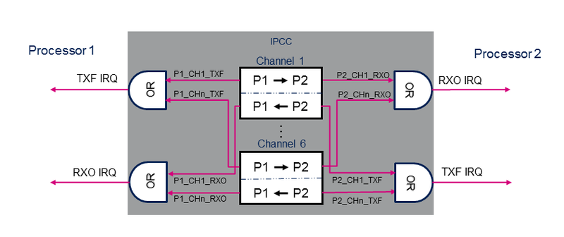
The IPCC (inter-processor communication controller) peripheral is used to exchange data between two processors. It provides a non blocking signaling mechanism to post and retrieve information in an atomic way. Note that shared memory buffers are allocated in the MCU SRAM, which is not part of the IPCC block.
The IPCC peripheral provides a hardware support to manage inter-processor communication between two processor instances. Each processor owns specific register bank and interrupts.
The IPCC provides the signaling for bidirectional channels.
Each channel is divided into two subchannels that offer a unidirectional signaling from the "sender" processor to the "receiver" processor:
- P1_TO_P2 subchannel
- P2_TO_P1 subchannel
A subchannel consists in:
- One flag that toggles between occupied and free: the flag is set to occupied by the "sender" processor and cleared by the "receiver" processor.
- Two associated interrupts (shared with the other channels):
- RXO: RX channel occupied, connected to the "receiver" processor.
- TXF: TX channel free, connected to the "sender" processor.
- Two associated interrupt masks multiplexing channel IRQs.
The IPCC supports the following channel operating modes:
- Simplex communication mode:
- Only one subchannel is used.
- Unidirectional messages: once the "sender" processor has posted the communication data in the memory, it sets the channel status flag to occupied. The "receiver" processor clears the flag when the message is treated.
- Half-duplex communication mode:
- Only one subchannel is used.
- Bidirectional messages: once the "sender" processor has posted the communication data in the memory, it sets the channel status flag to occupied. The "receiver" processor clears the flag when the message is treated and the response is available in shared memory.
- Full-duplex communication mode:
- The subchannels are used in Asynchronous mode.
- Any processor can post asynchronously a message by setting the subchannel status flag to occupied. The "receiver" processor clears the flag when the message is treated. This mode can be considered as a combination of two simplex modes on a given channel.
Refer to the reference manuals[1][2] for the complete list of features, and to the software frameworks and drivers, introduced below, to see which features are implemented.
32. Peripheral usage[edit | edit source]
This chapter is applicable in the scope of the OpenSTLinux BSP running on the Arm® Cortex®-A processor(s), and the FwST-M Package running on the Arm® Cortex®-M processor.
32.1. Processor interface assignment[edit | edit source]
32.1.1. On STM32MP15x lines [edit | edit source]
STMicroelectronics distribution uses the IPCC peripheral for inter-processor communication with the following configuration:
- The IPCC processor 1 interface (PROC1)is assigned to the Arm® Cortex®-A7, nonsecure context.
- The IPCC processor 2 interface (PROC2) is assigned to the Arm® Cortex®-M4 context.
32.1.2. On STM32MP21x lines and STM32MP23x lines [edit | edit source]
The IPCC1 peripheral is dedicated for the communication between the Arm® Cortex®-A35 and the Arm® Cortex®-M33. The interfaces are assigned in hardware to the Cortexes :
- The processor 1 interface (PROC1) is assigned by hardware to the Arm® Cortex®-A35, secure and nonsecure context.
- The processor 2 interface (PROC2) is assigned by hardware to the Arm® Cortex®-M33, secure and nonsecure context.
32.1.3. On STM32MP25x lines [edit | edit source]
- The IPCC1 peripheral is dedicated for the communication between the Arm® Cortex®-A35 and the Arm® Cortex®-M33. The interfaces are assigned in hardware to the Cortexes :
- The processor 1 interface (PROC1) is assigned by hardware to the Arm® Cortex®-A35, secure and nonsecure context.
- The processor 2 interface (PROC2) is assigned by hardware to the Arm® Cortex®-M33, secure and nonsecure context.
- The IPCC2 peripheral is dedicated for the communication between the Arm® Cortex®-A35 or the Arm® Cortex®-M33 and the Arm® Cortex®-M0+.
- The processor 1 interface (PROC1) is assigned by hardware to the Arm® Cortex®-M0+.
- The processor 2 interface (PROC2) is assignable to the Arm® Cortex®-A35 or the Arm® Cortex®-M33, secure and nonsecure context.
32.2. Boot time assignment[edit | edit source]
32.2.1. On STM32MP15x lines [edit | edit source]
The IPCC peripheral is not utilized during boot time in the OpenSTlinux distribution.
32.2.2. On STM32MP21x lines and STM32MP23x lines [edit | edit source]
32.2.2.1. For A35-TD flavor [edit | edit source]
The IPCC peripheral is not utilized during boot time in the OpenSTlinux distribution.
Click on ![]() to expand or collapse the legend...
to expand or collapse the legend...
| Domain | Peripheral | Boot time allocation | Comment | |||
|---|---|---|---|---|---|---|
| Instance | Cortex-A35 secure (ROM code) |
Cortex-A35 secure (TF-A BL2) |
Cortex-A35 nonsecure (U-Boot) | |||
| Coprocessor | IPCC |
IPCC1 | Shareable at internal peripheral level thanks to the RIF: see the boot time allocation per feature | |||
The below table shows the possible boot time allocations for the features of the IPCC1 instance.
| Feature | Boot time allocation |
Comment | ||
|---|---|---|---|---|
| Cortex-A35 secure (ROM code) |
Cortex-A35 secure (TF-A BL2) |
Cortex-A35 nonsecure (U-Boot) | ||
| CPU1 channel 1 | ⬚ | ⬚ | ||
| CPU1 channel 2 | ⬚ | ⬚ | ||
| CPU1 channel 3 | ⬚ | ⬚ | ||
| CPU1 channel 4 | ⬚ | ⬚ | ||
| CPU1 channel 5 | ⬚ | ⬚ | ||
| CPU1 channel 6 | ⬚ | ⬚ | ||
| CPU1 channel 7 | ⬚ | ⬚ | ||
| CPU1 channel 8 | ⬚ | ⬚ | ||
| CPU1 channel 9 | ⬚ | ⬚ | ||
| CPU1 channel 10 | ⬚ | ⬚ | ||
| CPU1 channel 11 | ⬚ | ⬚ | ||
| CPU1 channel 12 | ⬚ | ⬚ | ||
| CPU1 channel 13 | ⬚ | ⬚ | ||
| CPU1 channel 14 | ⬚ | ⬚ | ||
| CPU1 channel 15 | ⬚ | ⬚ | ||
| CPU1 channel 16 | ⬚ | ⬚ | ||
| CPU2 channel 1 | ||||
| CPU2 channel 2 | ||||
| CPU2 channel 3 | ||||
| CPU2 channel 4 | ||||
| CPU2 channel 5 | ||||
| CPU2 channel 6 | ||||
| CPU2 channel 7 | ||||
| CPU2 channel 8 | ||||
| CPU2 channel 9 | ||||
| CPU2 channel 10 | ||||
| CPU2 channel 11 | ||||
| CPU2 channel 12 | ||||
| CPU2 channel 13 | ||||
| CPU2 channel 14 | ||||
| CPU2 channel 15 | ||||
| CPU2 channel 16 | ||||
32.2.2.2. For M33-TD flavor [edit | edit source]
Click on ![]() to expand or collapse the legend...
to expand or collapse the legend...
| Domain | Peripheral | Boot time allocation | Comment | ||||
|---|---|---|---|---|---|---|---|
| Instance | Cortex-A35 secure (ROM code) |
Cortex-A35 secure (TF-A BL2) |
Cortex-A35 nonsecure (U-Boot) |
Cortex-M33 secure (MCUboot) | |||
| Coprocessor | IPCC |
IPCC1 | Shareable at internal peripheral level thanks to the RIF: see the boot time allocation per feature | ||||
The below table shows the possible boot time allocations for the features of the IPCC1 instance.
| Feature | Boot time allocation |
Comment | |||
|---|---|---|---|---|---|
| Cortex-A35 secure (ROM code) |
Cortex-A35 secure (TF-A BL2) |
Cortex-A35 nonsecure (U-Boot) |
Cortex-M33 secure (MCUboot) | ||
| CPU1 channel 1 | ⬚ | ⬚ | |||
| CPU1 channel 2 | ⬚ | ⬚ | |||
| CPU1 channel 3 | ⬚ | ⬚ | |||
| CPU1 channel 4 | ⬚ | ⬚ | |||
| CPU1 channel 5 | ⬚ | ⬚ | |||
| CPU1 channel 6 | ⬚ | ⬚ | |||
| CPU1 channel 7 | ⬚ | ⬚ | |||
| CPU1 channel 8 | ⬚ | ⬚ | |||
| CPU1 channel 9 | ⬚ | ⬚ | |||
| CPU1 channel 10 | ⬚ | ⬚ | |||
| CPU1 channel 11 | ⬚ | ⬚ | |||
| CPU1 channel 12 | ⬚ | ⬚ | |||
| CPU1 channel 13 | ⬚ | ⬚ | |||
| CPU1 channel 14 | ⬚ | ⬚ | |||
| CPU1 channel 15 | ⬚ | ⬚ | |||
| CPU1 channel 16 | ⬚ | ☑ | SCMI for system resource configuration controlled by the Cortex-M33 secure (TF-M) | ||
| CPU2 channel 1 | ⬚ | ||||
| CPU2 channel 2 | ⬚ | ||||
| CPU2 channel 3 | ⬚ | ||||
| CPU2 channel 4 | ⬚ | ||||
| CPU2 channel 5 | ⬚ | ||||
| CPU2 channel 6 | ⬚ | ||||
| CPU2 channel 7 | ⬚ | ||||
| CPU2 channel 8 | ⬚ | ||||
| CPU2 channel 9 | ⬚ | ||||
| CPU2 channel 10 | ⬚ | ||||
| CPU2 channel 11 | ⬚ | ||||
| CPU2 channel 12 | ⬚ | ||||
| CPU2 channel 13 | ⬚ | ||||
| CPU2 channel 14 | ⬚ | ||||
| CPU2 channel 15 | ⬚ | ||||
| CPU2 channel 16 | ☑ | SCMI for system resource configuration controlled by the Cortex-M33 secure (TF-M) | |||
32.2.3. On STM32MP25x lines [edit | edit source]
32.2.3.1. For A35-TD flavor [edit | edit source]
The IPCC peripherals are not utilized during boot time in the OpenSTlinux distribution.
Click on ![]() to expand or collapse the legend...
to expand or collapse the legend...
| Domain | Peripheral | Boot time allocation | Comment | |||
|---|---|---|---|---|---|---|
| Instance | Cortex-A35 secure (ROM code) |
Cortex-A35 secure (TF-A BL2) |
Cortex-A35 nonsecure (U-Boot) | |||
| Coprocessor | IPCC |
IPCC1 | Shareable at internal peripheral level thanks to the RIF: see the boot time allocation per feature | |||
| IPCC2 | Shareable at internal peripheral level thanks to the RIF: see the boot time allocation per feature | |||||
The below table shows the possible boot time allocations for the features of the IPCC1 instance.
| Feature | Boot time allocation |
Comment | ||
|---|---|---|---|---|
| Cortex-A35 secure (ROM code) |
Cortex-A35 secure (TF-A BL2) |
Cortex-A35 nonsecure (U-Boot) | ||
| CPU1 channel 1 | ⬚ | ⬚ | ||
| CPU1 channel 2 | ⬚ | ⬚ | ||
| CPU1 channel 3 | ⬚ | ⬚ | ||
| CPU1 channel 4 | ⬚ | ⬚ | ||
| CPU1 channel 5 | ⬚ | ⬚ | ||
| CPU1 channel 6 | ⬚ | ⬚ | ||
| CPU1 channel 7 | ⬚ | ⬚ | ||
| CPU1 channel 8 | ⬚ | ⬚ | ||
| CPU1 channel 9 | ⬚ | ⬚ | ||
| CPU1 channel 10 | ⬚ | ⬚ | ||
| CPU1 channel 11 | ⬚ | ⬚ | ||
| CPU1 channel 12 | ⬚ | ⬚ | ||
| CPU1 channel 13 | ⬚ | ⬚ | ||
| CPU1 channel 14 | ⬚ | ⬚ | ||
| CPU1 channel 15 | ⬚ | ⬚ | ||
| CPU1 channel 16 | ⬚ | ⬚ | ||
| CPU2 channel 1 | ||||
| CPU2 channel 2 | ||||
| CPU2 channel 3 | ||||
| CPU2 channel 4 | ||||
| CPU2 channel 5 | ||||
| CPU2 channel 6 | ||||
| CPU2 channel 7 | ||||
| CPU2 channel 8 | ||||
| CPU2 channel 9 | ||||
| CPU2 channel 10 | ||||
| CPU2 channel 11 | ||||
| CPU2 channel 12 | ||||
| CPU2 channel 13 | ||||
| CPU2 channel 14 | ||||
| CPU2 channel 15 | ||||
| CPU2 channel 16 | ||||
The below table shows the possible boot time allocations for the features of the IPCC2 instance.
| Feature | Boot time allocation |
Comment | ||
|---|---|---|---|---|
| Cortex-A35 secure (ROM code) |
Cortex-A35 secure (TF-A BL2) |
Cortex-A35 nonsecure (U-Boot) | ||
| CPU1 channel 1 | ⬚ | ⬚ | ||
| CPU1 channel 2 | ⬚ | ⬚ | ||
| CPU1 channel 3 | ⬚ | ⬚ | ||
| CPU1 channel 4 | ⬚ | ⬚ | ||
| CPU2 channel 1 | ||||
| CPU2 channel 2 | ||||
| CPU2 channel 3 | ||||
| CPU2 channel 4 | ||||
32.2.3.2. For M33-TD flavor [edit | edit source]
Click on ![]() to expand or collapse the legend...
to expand or collapse the legend...
| Domain | Peripheral | Boot time allocation | Comment | ||||
|---|---|---|---|---|---|---|---|
| Instance | Cortex-A35 secure (ROM code) |
Cortex-A35 secure (TF-A BL2) |
Cortex-A35 nonsecure (U-Boot) |
Cortex-M33 secure (MCUboot) | |||
| Coprocessor | IPCC |
IPCC1 | Shareable at internal peripheral level thanks to the RIF: see the boot time allocation per feature | ||||
| IPCC2 | Shareable at internal peripheral level thanks to the RIF: see the boot time allocation per feature | ||||||
The below table shows the possible boot time allocations for the features of the IPCC1 instance.
| Feature | Boot time allocation |
Comment | |||
|---|---|---|---|---|---|
| Cortex-A35 secure (ROM code) |
Cortex-A35 secure (TF-A BL2) |
Cortex-A35 nonsecure (U-Boot) |
Cortex-M33 secure (MCUboot) | ||
| CPU1 channel 1 | ⬚ | ⬚ | |||
| CPU1 channel 2 | ⬚ | ⬚ | |||
| CPU1 channel 3 | ⬚ | ⬚ | |||
| CPU1 channel 4 | ⬚ | ⬚ | |||
| CPU1 channel 5 | ⬚ | ⬚ | |||
| CPU1 channel 6 | ⬚ | ⬚ | |||
| CPU1 channel 7 | ⬚ | ⬚ | |||
| CPU1 channel 8 | ⬚ | ⬚ | |||
| CPU1 channel 9 | ⬚ | ⬚ | |||
| CPU1 channel 10 | ⬚ | ⬚ | |||
| CPU1 channel 11 | ⬚ | ⬚ | |||
| CPU1 channel 12 | ⬚ | ⬚ | |||
| CPU1 channel 13 | ⬚ | ⬚ | |||
| CPU1 channel 14 | ⬚ | ⬚ | |||
| CPU1 channel 15 | ⬚ | ⬚ | |||
| CPU1 channel 16 | ⬚ | ☑ | SCMI for system resource configuration controlled by the Cortex-M33 secure (TF-M) | ||
| CPU2 channel 1 | ⬚ | ||||
| CPU2 channel 2 | ⬚ | ||||
| CPU2 channel 3 | ⬚ | ||||
| CPU2 channel 4 | ⬚ | ||||
| CPU2 channel 5 | ⬚ | ||||
| CPU2 channel 6 | ⬚ | ||||
| CPU2 channel 7 | ⬚ | ||||
| CPU2 channel 8 | ⬚ | ||||
| CPU2 channel 9 | ⬚ | ||||
| CPU2 channel 10 | ⬚ | ||||
| CPU2 channel 11 | ⬚ | ||||
| CPU2 channel 12 | ⬚ | ||||
| CPU2 channel 13 | ⬚ | ||||
| CPU2 channel 14 | ⬚ | ||||
| CPU2 channel 15 | ⬚ | ||||
| CPU2 channel 16 | ☑ | SCMI for system resource configuration controlled by the Cortex-M33 secure (TF-M) | |||
The below table shows the possible boot time allocations for the features of the IPCC2 instance.
| Feature | Boot time allocation |
Comment | |||
|---|---|---|---|---|---|
| Cortex-A35 secure (ROM code) |
Cortex-A35 secure (TF-A BL2) |
Cortex-A35 nonsecure (U-Boot) |
Cortex-M33 secure (MCUboot) | ||
| CPU1 channel 1 | ⬚ | ⬚ | ⬚ | ||
| CPU1 channel 2 | ⬚ | ⬚ | ⬚ | ||
| CPU1 channel 3 | ⬚ | ⬚ | ⬚ | ||
| CPU1 channel 4 | ⬚ | ⬚ | ⬚ | ||
| CPU2 channel 1 | |||||
| CPU2 channel 2 | |||||
| CPU2 channel 3 | |||||
| CPU2 channel 4 | |||||
32.3. Runtime assignment[edit | edit source]
It does not make sense to allocate the IPCC to a single runtime execution context. It is consequently enabled by default for both cores in the STM32CubeMX.
32.3.1. On STM32MP15x lines [edit | edit source]
Click on ![]() to expand or collapse the legend...
to expand or collapse the legend...
| Domain | Peripheral | Runtime allocation | Comment | |||
|---|---|---|---|---|---|---|
| Instance | Cortex-A7 secure (OP-TEE) |
Cortex-A7 nonsecure (Linux) |
Cortex-M4 (STM32Cube) | |||
| Coprocessor | IPCC | IPCC | ☑ | ☑ | Shared (none or both) | |
| Processor interface | Context | Comment | ||
|---|---|---|---|---|
| Cortex-A7 nonsecure (Linux) |
Cortex-M4 (STM32Cube) | |||
| PROC1 channel 1 | ☑ | RPMsg transfer from Cortex-M to Cortex-A
Full-duplex communication:
| ||
| PROC1 channel 2 | ☑ | RPMsg transfer from Cortex-A to Cortex-M
Full-duplex communication:
| ||
| PROC1 channel 3 | ☑ | Simplex communication used by the remote framework to request the Cortex-M4 to shutdown. | ||
| PROC1 channel 4 | ☐ | |||
| PROC1 channel 5 | ☐ | |||
| PROC1 channel 6 | ☐ | |||
| PROC2 channel 1 | ☑ | RPMsg transfer from Cortex-M to Cortex-A
Full-duplex communication:
| ||
| PROC2 channel 2 | ☑ | RPMsg transfer from Cortex-A to Cortex-M
Full-duplex communication:
| ||
| PROC2 channel 3 | ☑ | Simplex communication used by the remote framework to request the Cortex-M4 to shutdown. | ||
| PROC2 channel 4 | ☐ | |||
| PROC2 channel 5 | ☐ | |||
| PROC2 channel 6 | ☐ | |||
32.3.2. On STM32MP21x lines and STM32MP23x lines [edit | edit source]
32.3.2.1. For A35-TD flavor [edit | edit source]
Click on ![]() to expand or collapse the legend...
to expand or collapse the legend...
| Domain | Peripheral | Runtime allocation | Comment | ||||
|---|---|---|---|---|---|---|---|
| Instance | Cortex-A35 secure (OP-TEE / TF-A BL31) |
Cortex-A35 nonsecure (Linux) |
Cortex-M33 secure (TF-M) |
Cortex-M33 nonsecure (STM32Cube) | |||
| Coprocessor | IPCC |
IPCC1 | Shareable at internal peripheral level thanks to the RIF: see the runtime allocation per feature | ||||
The below table shows the possible runtime allocations for the features of the IPCC1 instance.
| Feature | Runtime allocation |
Comment | |||
|---|---|---|---|---|---|
| Cortex-A35 secure (OP-TEE / TF-A BL31) |
Cortex-A35 nonsecure (Linux) |
Cortex-M33 secure (TF-M) |
Cortex-M33 nonsecure (STM32Cube) | ||
| CPU1 channel 1 | ☐OP-TEE | ☑ | RPMsg transfer from Cortex-M to Cortex-A
Full-duplex communication:
| ||
| CPU1 channel 2 | ☐OP-TEE | ☑ | RPMsg transfer from Cortex-A to Cortex-M
Full-duplex communication:
| ||
| CPU1 channel 3 | ☐OP-TEE | ☑ | Simplex communication used by the remote framework to request the Cortex-M33 to shutdown. | ||
| CPU1 channel 4 | ☐OP-TEE | ☐ | |||
| CPU1 channel 5 | ☐OP-TEE | ☐ | |||
| CPU1 channel 6 | ☐OP-TEE | ☐ | |||
| CPU1 channel 7 | ☐OP-TEE | ☐ | |||
| CPU1 channel 8 | ☐OP-TEE | ☐ | |||
| CPU1 channel 9 | ☐OP-TEE | ☐ | |||
| CPU1 channel 10 | ☐OP-TEE | ☐ | |||
| CPU1 channel 11 | ☐OP-TEE | ☐ | |||
| CPU1 channel 12 | ☐OP-TEE | ☐ | |||
| CPU1 channel 13 | ☐OP-TEE | ☐ | |||
| CPU1 channel 14 | ☐OP-TEE | ☐ | |||
| CPU1 channel 15 | ☐OP-TEE | ☐ | |||
| CPU1 channel 16 | ☑OP-TEE | ☐ | SCMI for system resource configuration controlled by the Cortex-A35 secure (OPTEE) | ||
| CPU2 channel 1 | ☐ | ☑ | RPMsg transfer from Cortex-M to Cortex-A
Full-duplex communication:
| ||
| CPU2 channel 2 | ☐ | ☑ | RPMsg transfer from Cortex-A to Cortex-M
Full-duplex communication:
| ||
| CPU2 channel 3 | ☐ | ☑ | Simplex communication used by the remote framework to request the Cortex-M4 to shutdown. | ||
| CPU2 channel 4 | ☐ | ☐ | |||
| CPU2 channel 5 | ☐ | ☐ | |||
| CPU2 channel 6 | ☐ | ☐ | |||
| CPU2 channel 7 | ☐ | ☐ | |||
| CPU2 channel 8 | ☐ | ☐ | |||
| CPU2 channel 9 | ☐ | ☐ | |||
| CPU2 channel 10 | ☐ | ☐ | |||
| CPU2 channel 11 | ☐ | ☐ | |||
| CPU2 channel 12 | ☐ | ☐ | |||
| CPU2 channel 13 | ☐ | ☐ | |||
| CPU2 channel 14 | ☐ | ☐ | |||
| CPU2 channel 15 | ☐ | ☐ | |||
| CPU2 channel 16 | ☐ | ☑ | SCMI for system resource configuration controlled by the Cortex-A35 secure (OPTEE) | ||
32.3.2.2. For M33-TD flavor [edit | edit source]
Click on ![]() to expand or collapse the legend...
to expand or collapse the legend...
| Domain | Peripheral | Runtime allocation | Comment | ||||
|---|---|---|---|---|---|---|---|
| Instance | Cortex-A35 secure (OP-TEE / TF-A BL31) |
Cortex-A35 nonsecure (Linux) |
Cortex-M33 secure (TF-M) |
Cortex-M33 nonsecure (STM32Cube) | |||
| Coprocessor | IPCC |
IPCC1 | Shareable at internal peripheral level thanks to the RIF: see the runtime allocation per feature | ||||
The below table shows the possible runtime allocations for the features of the IPCC1 instance.
| Feature | Runtime allocation |
Comment | |||
|---|---|---|---|---|---|
| Cortex-A35 secure (OP-TEE / TF-A BL31) |
Cortex-A35 nonsecure (Linux) |
Cortex-M33 secure (TF-M) |
Cortex-M33 nonsecure (STM32Cube) | ||
| CPU1 channel 1 | ☐OP-TEE | ☑ | RPMsg transfer from Cortex-M to Cortex-A
Full-duplex communication:
| ||
| CPU1 channel 2 | ☐OP-TEE | ☑ | RPMsg transfer from Cortex-A to Cortex-M
Full-duplex communication:
| ||
| CPU1 channel 3 | ☐OP-TEE | ☑ | Simplex communication used by the remote framework to request the Cortex-M33 to shutdown. | ||
| CPU1 channel 4 | ☐OP-TEE | ☐ | |||
| CPU1 channel 5 | ☐OP-TEE | ☐ | |||
| CPU1 channel 6 | ☐OP-TEE | ☐ | |||
| CPU1 channel 7 | ☐OP-TEE | ☐ | |||
| CPU1 channel 8 | ☐OP-TEE | ☐ | |||
| CPU1 channel 9 | ☐OP-TEE | ☐ | |||
| CPU1 channel 10 | ☐OP-TEE | ☐ | |||
| CPU1 channel 11 | ☐OP-TEE | ☐ | |||
| CPU1 channel 12 | ☐OP-TEE | ☐ | |||
| CPU1 channel 13 | ☐OP-TEE | ☐ | |||
| CPU1 channel 14 | ☑TF-A | ☐ | PSA service for platform secure architecture service controlled by the Cortex-M33 secure (TF-M) | ||
| CPU1 channel 15 | ☑OP-TEE | ☐ | SCMI for system resource configuration controlled by the Cortex-M33 secure (TF-M) | ||
| CPU1 channel 16 | ☐OP-TEE | ☑ | SCMI for system resource configuration controlled by the Cortex-M33 secure (TF-M) | ||
| CPU2 channel 1 | ☐ | ☑ | RPMsg transfer from Cortex-M to Cortex-A
Full-duplex communication:
| ||
| CPU2 channel 2 | ☐ | ☑ | RPMsg transfer from Cortex-A to Cortex-M
Full-duplex communication:
| ||
| CPU2 channel 3 | ☐ | ☑ | Simplex communication used by the remote framework to request the Cortex-M4 to shutdown. | ||
| CPU2 channel 4 | ☐ | ☐ | |||
| CPU2 channel 5 | ☐ | ☐ | |||
| CPU2 channel 6 | ☐ | ☐ | |||
| CPU2 channel 7 | ☐ | ☐ | |||
| CPU2 channel 8 | ☐ | ☐ | |||
| CPU2 channel 9 | ☐ | ☐ | |||
| CPU2 channel 10 | ☐ | ☐ | |||
| CPU2 channel 11 | ☐ | ☐ | |||
| CPU2 channel 12 | ☐ | ☐ | |||
| CPU2 channel 13 | ☐ | ☐ | |||
| CPU2 channel 14 | ☑ | ☐ | PSA service for platform secure architecture service controlled by the Cortex-M33 secure (TF-M) | ||
| CPU2 channel 15 | ☑ | ☐ | SCMI for system resource configuration controlled by the Cortex-M33 secure (TF-M) | ||
| CPU2 channel 16 | ☑ | ☐ | SCMI for system resource configuration controlled by the Cortex-M33 secure (TF-M) | ||
32.3.3. On STM32MP25x lines [edit | edit source]
32.3.3.1. For A35-TD flavor [edit | edit source]
Click on ![]() to expand or collapse the legend...
to expand or collapse the legend...
| Domain | Peripheral | Runtime allocation | Comment | |||||
|---|---|---|---|---|---|---|---|---|
| Instance | Cortex-A35 secure (OP-TEE / TF-A BL31) |
Cortex-A35 nonsecure (Linux) |
Cortex-M33 secure (TF-M) |
Cortex-M33 nonsecure (STM32Cube) |
Cortex-M0+ (STM32Cube) | |||
| Coprocessor | IPCC |
IPCC1 | Shareable at internal peripheral level thanks to the RIF: see the runtime allocation per feature | |||||
| IPCC2 | Shareable at internal peripheral level thanks to the RIF: see the runtime allocation per feature | |||||||
The below table shows the possible runtime allocations for the features of the IPCC1 instance.
| Feature | Runtime allocation |
Comment | ||||
|---|---|---|---|---|---|---|
| Cortex-A35 secure (OP-TEE / TF-A BL31) |
Cortex-A35 nonsecure (Linux) |
Cortex-M33 secure (TF-M) |
Cortex-M33 nonsecure (STM32Cube) |
Cortex-M0+ (STM32Cube) | ||
| CPU1 channel 1 | ☐OP-TEE | ☑ | RPMsg transfer from Cortex-M to Cortex-A
Full-duplex communication:
| |||
| CPU1 channel 2 | ☐OP-TEE | ☑ | RPMsg transfer from Cortex-A to Cortex-M
Full-duplex communication:
| |||
| CPU1 channel 3 | ☐OP-TEE | ☑ | Simplex communication used by the remote framework to request the Cortex-M33 to shutdown. | |||
| CPU1 channel 4 | ☐OP-TEE | ☐ | ||||
| CPU1 channel 5 | ☐OP-TEE | ☐ | ||||
| CPU1 channel 6 | ☐OP-TEE | ☐ | ||||
| CPU1 channel 7 | ☐OP-TEE | ☐ | ||||
| CPU1 channel 8 | ☐OP-TEE | ☐ | ||||
| CPU1 channel 9 | ☐OP-TEE | ☐ | ||||
| CPU1 channel 10 | ☐OP-TEE | ☐ | ||||
| CPU1 channel 11 | ☐OP-TEE | ☐ | ||||
| CPU1 channel 12 | ☐OP-TEE | ☐ | ||||
| CPU1 channel 13 | ☐OP-TEE | ☐ | ||||
| CPU1 channel 14 | ☐OP-TEE | ☐ | ||||
| CPU1 channel 15 | ☐OP-TEE | ☐ | ||||
| CPU1 channel 16 | ☑OP-TEE | ☐ | SCMI for system resource configuration controlled by the Cortex-A35 secure (OPTEE) | |||
| CPU2 channel 1 | ☐ | ☑ | RPMsg transfer from Cortex-M to Cortex-A
Full-duplex communication:
| |||
| CPU2 channel 2 | ☐ | ☑ | RPMsg transfer from Cortex-A to Cortex-M
Full-duplex communication:
| |||
| CPU2 channel 3 | ☐ | ☑ | Simplex communication used by the remote framework to request the Cortex-M33 to shutdown. | |||
| CPU2 channel 4 | ☐ | ☐ | ||||
| CPU2 channel 5 | ☐ | ☐ | ||||
| CPU2 channel 6 | ☐ | ☐ | ||||
| CPU2 channel 7 | ☐ | ☐ | ||||
| CPU2 channel 8 | ☐ | ☐ | ||||
| CPU2 channel 9 | ☐ | ☐ | ||||
| CPU2 channel 10 | ☐ | ☐ | ||||
| CPU2 channel 11 | ☐ | ☐ | ||||
| CPU2 channel 12 | ☐ | ☐ | ||||
| CPU2 channel 13 | ☐ | ☐ | ||||
| CPU2 channel 14 | ☐ | ☐ | ||||
| CPU2 channel 15 | ☐ | ☐ | ||||
| CPU2 channel 16 | ☐ | ☑ | SCMI for system resource configuration controlled by the Cortex-A35 secure (OPTEE) | |||
The below table shows the possible runtime allocations for the features of the IPCC2 instance.
| Feature | Runtime allocation |
Comment | ||||
|---|---|---|---|---|---|---|
| Cortex-A35 secure (OP-TEE / TF-A BL31) |
Cortex-A35 nonsecure (Linux) |
Cortex-M33 secure (TF-M) |
Cortex-M33 nonsecure (STM32Cube) |
Cortex-M0+ (STM32Cube) | ||
| CPU1 channel 1 | ☐OP-TEE | ☑ | ☐ | ☐ | Interprocessor communication | |
| CPU1 channel 2 | ☐OP-TEE | ☑ | ☐ | ☐ | Simplex communication used by the remote framework to request the Cortex-M0+ to shutdown. | |
| CPU1 channel 3 | ☐OP-TEE | ☐ | ☐ | ☐ | ||
| CPU1 channel 4 | ☐OP-TEE | ☐ | ☐ | ☐ | ||
| CPU2 channel 1 | ☑ | Interprocessor communication | ||||
| CPU2 channel 2 | ☑ | Simplex communication used by the remote framework to request the Cortex-M0+ to shutdown. | ||||
| CPU2 channel 3 | ☐ | |||||
| CPU2 channel 4 | ☐ | |||||
32.3.3.2. For M33-TD flavor [edit | edit source]
Click on ![]() to expand or collapse the legend...
to expand or collapse the legend...
| Domain | Peripheral | Runtime allocation | Comment | |||||
|---|---|---|---|---|---|---|---|---|
| Instance | Cortex-A35 secure (OP-TEE / TF-A BL31) |
Cortex-A35 nonsecure (Linux) |
Cortex-M33 secure (TF-M) |
Cortex-M33 nonsecure (STM32Cube) |
Cortex-M0+ (STM32Cube) | |||
| Coprocessor | IPCC |
IPCC1 | Shareable at internal peripheral level thanks to the RIF: see the runtime allocation per feature | |||||
| IPCC2 | Shareable at internal peripheral level thanks to the RIF: see the runtime allocation per feature | |||||||
The below table shows the possible runtime allocations for the features of the IPCC1 instance.
| Feature | Runtime allocation |
Comment | ||||
|---|---|---|---|---|---|---|
| Cortex-A35 secure (OP-TEE / TF-A BL31) |
Cortex-A35 nonsecure (Linux) |
Cortex-M33 secure (TF-M) |
Cortex-M33 nonsecure (STM32Cube) |
Cortex-M0+ (STM32Cube) | ||
| CPU1 channel 1 | ☐OP-TEE | ☑ | RPMsg transfer from Cortex-M to Cortex-A
Full-duplex communication:
| |||
| CPU1 channel 2 | ☐OP-TEE | ☑ | RPMsg transfer from Cortex-A to Cortex-M
Full-duplex communication:
| |||
| CPU1 channel 3 | ☐OP-TEE | ☑ | Simplex communication used by the remote framework to request the Cortex-A to shutdown. | |||
| CPU1 channel 4 | ☐OP-TEE | ☐ | ||||
| CPU1 channel 5 | ☐OP-TEE | ☐ | ||||
| CPU1 channel 6 | ☐OP-TEE | ☐ | ||||
| CPU1 channel 7 | ☐OP-TEE | ☐ | ||||
| CPU1 channel 8 | ☐OP-TEE | ☐ | ||||
| CPU1 channel 9 | ☐OP-TEE | ☐ | ||||
| CPU1 channel 10 | ☐OP-TEE | ☐ | ||||
| CPU1 channel 11 | ☐OP-TEE | ☐ | ||||
| CPU1 channel 12 | ☐OP-TEE | ☐ | ||||
| CPU1 channel 13 | ☐OP-TEE | ☐ | ||||
| CPU1 channel 14 | ☑TF-A | ☐ | PSA service for platform secure architecture service controlled by the Cortex-M33 secure (TF-M) | |||
| CPU1 channel 15 | ☑TF-A | ☐ | SCMI for system resource configuration controlled by the Cortex-M33 secure (TF-M) | |||
| CPU1 channel 16 | ☐OP-TEE | ☑ | SCMI for system resource configuration controlled by the Cortex-M33 secure (TF-M) | |||
| CPU2 channel 1 | ☐ | ☑ | RPMsg transfer from Cortex-M to Cortex-A
Full-duplex communication:
| |||
| CPU2 channel 2 | ☐ | ☑ | RPMsg transfer from Cortex-A to Cortex-M
Full-duplex communication:
| |||
| CPU2 channel 3 | ☐ | ☑ | Simplex communication used by the remote framework to request the Cortex-A to shutdown. | |||
| CPU2 channel 4 | ☐ | ☐ | ||||
| CPU2 channel 5 | ☐ | ☐ | ||||
| CPU2 channel 6 | ☐ | ☐ | ||||
| CPU2 channel 7 | ☐ | ☐ | ||||
| CPU2 channel 8 | ☐ | ☐ | ||||
| CPU2 channel 9 | ☐ | ☐ | ||||
| CPU2 channel 10 | ☐ | ☐ | ||||
| CPU2 channel 11 | ☐ | ☐ | ||||
| CPU2 channel 12 | ☐ | ☐ | ||||
| CPU2 channel 13 | ☐ | ☐ | ||||
| CPU2 channel 14 | ☑ | ☐ | PSA service for platform secure architecture service controlled by the Cortex-M33 secure (TF-M) | |||
| CPU2 channel 15 | ☑ | ☐ | SCMI for system resource configuration controlled by the Cortex-M33 secure (TF-M) | |||
| CPU2 channel 16 | ☑ | ☐ | SCMI for system resource configuration controlled by the Cortex-M33 secure (TF-M) | |||
The below table shows the possible runtime allocations for the features of the IPCC2 instance.
| Feature | Runtime allocation |
Comment | ||||
|---|---|---|---|---|---|---|
| Cortex-A35 secure (OP-TEE / TF-A BL31) |
Cortex-A35 nonsecure (Linux) |
Cortex-M33 secure (TF-M) |
Cortex-M33 nonsecure (STM32Cube) |
Cortex-M0+ (STM32Cube) | ||
| CPU1 channel 1 | ☐OP-TEE | ☐ | ☐ | ☐ | ||
| CPU1 channel 2 | ☐OP-TEE | ☐ | ☐ | ☐ | ||
| CPU1 channel 3 | ☐OP-TEE | ☐ | ☐ | ☐ | ||
| CPU1 channel 4 | ☐OP-TEE | ☐ | ☐ | ☐ | ||
| CPU2 channel 1 | ☐ | |||||
| CPU2 channel 2 | ☐ | |||||
| CPU2 channel 3 | ☐ | |||||
| CPU2 channel 4 | ☐ | |||||
33. Software frameworks and drivers[edit | edit source]
Below are listed the software frameworks and drivers managing the IPCC peripheral for the embedded software components listed in the above tables.
- Linux®: mailbox framework
- STM32Cube: IPCC HAL driver and header file of IPCC HAL module
34. How to assign and configure the peripheral[edit | edit source]
The peripheral assignment can be done via the STM32CubeMX graphical tool (and manually completed if needed).
This tool also helps to configure the peripheral:
- partial device trees (pin control and clock tree) generation for the OpenSTLinux software components,
- HAL initialization code generation for the STM32CubeMPU Package.
The configuration is applied by the firmware running in the context in which the peripheral is assigned.The IPCC peripheral is shared between the Arm Cortex-A and Cortex-M contexts. A particular attention must therefore be paid to have a complementary configuration on both contexts.
35. Article purpose[edit | edit source]
The purpose of this article is to:
- briefly introduce the HSEM peripheral and its main features,
- indicate the peripheral instances assignment at boot time and their assignment at runtime (including whether instances can be allocated to secure contexts),
- list the software frameworks and drivers managing the peripheral,
- explain how to configure the peripheral.
36. Peripheral overview[edit | edit source]
The HSEM (hardware spinlock) peripheral is used to provide synchronization and mutual exclusion between heterogeneous processors.
- 32 hardware semaphores are available on the platform.
- semaphores could be accessed by the Arm® Cortex®-A7 core and the Arm® Cortex®-M4
Refer to the STM32MP15 reference manuals for the complete list of features, and to the software frameworks and drivers, introduced below, to see which features are implemented.
37. Peripheral usage[edit | edit source]
This chapter is applicable in the scope of the OpenSTLinux BSP running on the Arm® Cortex®-A processor(s), and the STM32CubeMPU Package running on the Arm® Cortex®-M processor.
37.1. Boot time assignment[edit | edit source]
37.1.1. On STM32MP15x lines [edit | edit source]
The hardware semaphore is used at boot time for GPIO access protection between the Arm® Cortex®-A7 and Cortex®-M4 cores. See Protecting GPIO and EXTI system resources by hardware semaphores for details.
Click on ![]() to expand or collapse the legend...
to expand or collapse the legend...
| Domain | Peripheral | Boot time allocation | Comment | |||
|---|---|---|---|---|---|---|
| Instance | Cortex-A7 secure (ROM code) |
Cortex-A7 secure (TF-A BL2) |
Cortex-A7 nonsecure (U-Boot) | |||
| Coprocessor | HSEM | HSEM | ☐ | |||
37.2. Runtime assignment[edit | edit source]
37.2.1. On STM32MP15x lines [edit | edit source]
It does not make sense to allocate HSEM to a single runtime execution context, that is why it is enabled by default for both cores in the STM32CubeMX.
The hardware semaphore is used at runtime for GPIO and EXTI access protection between the Arm® Cortex®-A7 and Cortex®-M4 cores. See Protecting GPIO and EXTI system resources by hardware semaphores for details.
Click on ![]() to expand or collapse the legend...
to expand or collapse the legend...
| Domain | Peripheral | Runtime allocation | Comment | |||
|---|---|---|---|---|---|---|
| Instance | Cortex-A7 secure (OP-TEE) |
Cortex-A7 nonsecure (Linux) |
Cortex-M4 (STM32Cube) | |||
| Coprocessor | HSEM | HSEM | ⬚ | ☑ | ☑ | |
38. Software frameworks and drivers[edit | edit source]
Below are listed the software frameworks and drivers managing the HSEM peripheral for the embedded software components listed in the above tables.
- Linux®: hardware spinlock framework
- STM32Cube: HSEM HAL driver and header file of HSEM HAL module
39. How to assign and configure the peripheral[edit | edit source]
The peripheral assignment can be done via the STM32CubeMX graphical tool (and manually completed if needed).
This tool also helps to configure the peripheral:
- partial device trees (pin control and clock tree) generation for the OpenSTLinux software components,
- HAL initialization code generation for the STM32CubeMPU Package.
The configuration is applied by the firmware running in the context in which the peripheral is assigned.
The HSEM peripheral is shared between the Cortex-A and Cortex-M contexts, so a particular attention must be paid to have a complementary configuration on both contexts.
40. Article purpose[edit | edit source]
The purpose of this article is to:
- briefly introduce the RTC peripheral and its main features,
- indicate the peripheral instances assignment at boot time and their assignment at runtime (including whether instances can be allocated to secure contexts),
- list the software frameworks and drivers managing the peripheral,
- explain how to configure the peripheral.
41. Peripheral overview[edit | edit source]
The RTC peripheral is used to provide the date and clock to the application. It supports programmable alarms and wake up capabilities.
Refer to the STM32 MPU reference manuals for the complete list of features, and to the software frameworks and drivers, introduced below, to see which features are implemented.
42. Peripheral usage[edit | edit source]
This chapter is applicable in the scope of the OpenSTLinux BSP running on the Arm® Cortex®-A processor(s), and the FwST-M Package running on the Arm® Cortex®-M processor.
42.1. Boot time assignment[edit | edit source]
42.1.1. On STM32MP1 series[edit | edit source]
By default after a backup domain power-on reset (performed at boot time), all RTC registers can be read or written in both secure and non-secure modes.
In OpenSTLinux distribution, the first stage bootloader (FSBL, running in secure mode) keeps this default configuration, leaving full control to Linux® at runtime.
The RTC peripheral is able to generate two interrupts:
- A secure interrupt, connected to the Arm® Cortex®-A7 GIC, not used in OpenSTLinux distribution.
- A non-secure interrupt, connected both to Arm® Cortex®-A7 GIC and Cortex-M4 NVIC (STM32MP15x lines only): this interrupt is used on Linux® and by default in OpenSTLinux distribution.
The RTC peripheral is part of the backup domain which reset and clock are controlled via the RCC by the first stage bootloader (FSBL, running in secure mode) at boot time.
The RTC reset occurs when the backup domain is reset. To avoid clearing the TAMP register contents, this is only done on cold boot, not on wake up.
Click on ![]() to expand or collapse the legend...
to expand or collapse the legend...
| Domain | Peripheral | Boot time allocation | Comment | |||
|---|---|---|---|---|---|---|
| Instance | Cortex-A7 secure (ROM code) |
Cortex-A7 secure (TF-A BL2) |
Cortex-A7 nonsecure (U-Boot) | |||
| Core | RTC | RTC | ⬚ | ☐ | ||
42.1.2. On STM32MP2 series[edit | edit source]
42.1.2.1. For A35-TD flavor [edit | edit source]
Click on ![]() to expand or collapse the legend...
to expand or collapse the legend...
| Domain | Peripheral | Boot time allocation | Comment | |||
|---|---|---|---|---|---|---|
| Instance | Cortex-A35 secure (ROM code) |
Cortex-A35 secure (TF-A BL2) |
Cortex-A35 nonsecure (U-Boot) | |||
| Core | RTC |
RTC | Shareable at internal peripheral level thanks to the RIF: see the boot time allocation per feature | |||
The below table shows the possible boot time allocations for the features of the RTC instance.
| Feature | Boot time allocation |
Comment | ||
|---|---|---|---|---|
| Cortex-A35 secure (ROM code) |
Cortex-A35 secure (TF-A BL2) |
Cortex-A35 nonsecure (U-Boot) | ||
| Alarm A | ⬚ | ☐ | ||
| Alarm B | ⬚ | ⬚ | ||
| Wakeup timer | ⬚ | ☐ | ||
| Timestamp | ⬚ | ☐ | ||
| Calibration | ⬚ | ☐ | ||
| Initialization | ⬚ | ☐ | ||
42.1.2.2. For M33-TD flavor [edit | edit source]
Click on ![]() to expand or collapse the legend...
to expand or collapse the legend...
| Domain | Peripheral | Boot time allocation | Comment | ||||
|---|---|---|---|---|---|---|---|
| Instance | Cortex-A35 secure (ROM code) |
Cortex-A35 secure (TF-A BL2) |
Cortex-A35 nonsecure (U-Boot) |
Cortex-M33 secure (MCUboot) | |||
| Core | RTC |
RTC | Shareable at internal peripheral level thanks to the RIF: see the boot time allocation per feature | ||||
The below table shows the possible boot time allocations for the features of the RTC instance.
| Feature | Boot time allocation |
Comment | |||
|---|---|---|---|---|---|
| Cortex-A35 secure (ROM code) |
Cortex-A35 secure (TF-A BL2) |
Cortex-A35 nonsecure (U-Boot) |
Cortex-M33 secure (MCUboot) | ||
| Alarm A | ⬚ | ☐ | ⬚ | ||
| Alarm B | ⬚ | ⬚ | ⬚ | ||
| Wakeup timer | ⬚ | ☐ | ⬚ | ||
| Timestamp | ⬚ | ☐ | ⬚ | ||
| Calibration | ⬚ | ☐ | ⬚ | ||
| Initialization | ⬚ | ☐ | ⬚ | ||
42.2. Runtime assignment[edit | edit source]
42.2.1. On STM32MP13x lines [edit | edit source]
Click on ![]() to expand or collapse the legend...
to expand or collapse the legend...
| Domain | Peripheral | Runtime allocation | Comment | ||
|---|---|---|---|---|---|
| Instance | Cortex-A7 secure (OP-TEE) |
Cortex-A7 nonsecure (Linux) | |||
| Core | RTC | RTC | ☑ | ☐ | RTC is mandatory to resynchronize STGEN after exiting low-power modes. |
42.2.2. On STM32MP15x lines [edit | edit source]
Click on ![]() to expand or collapse the legend...
to expand or collapse the legend...
| Domain | Peripheral | Runtime allocation | Comment | |||
|---|---|---|---|---|---|---|
| Instance | Cortex-A7 secure (OP-TEE) |
Cortex-A7 nonsecure (Linux) |
Cortex-M4 (STM32Cube) | |||
| Core | RTC | RTC | ☑ | ☐ | ☐ | RTC is mandatory to resynchronize STGEN after exiting low-power modes. |
42.2.3. On STM32MP21x lines and STM32MP23x lines [edit | edit source]
The tables below are applicable to any TD flavor (A35-TD or M33-TD) ![]() .
.
Click on ![]() to expand or collapse the legend...
to expand or collapse the legend...
| Domain | Peripheral | Runtime allocation | Comment | ||||
|---|---|---|---|---|---|---|---|
| Instance | Cortex-A35 secure (OP-TEE / TF-A BL31) |
Cortex-A35 nonsecure (Linux) |
Cortex-M33 secure (TF-M) |
Cortex-M33 nonsecure (STM32Cube) | |||
| Core | RTC |
RTC | Shareable at internal peripheral level thanks to the RIF: see the runtime allocation per feature | RTC is mandatory to resynchronize STGEN after exiting low-power modes. | |||
The below table shows the possible runtime allocations for the features of the RTC instance.
| Feature | Runtime allocation |
Comment | |||
|---|---|---|---|---|---|
| Cortex-A35 secure (OP-TEE / TF-A BL31) |
Cortex-A35 nonsecure (Linux) |
Cortex-M33 secure (TF-M) |
Cortex-M33 nonsecure (STM32Cube) | ||
| Alarm A | ⬚TF-A BL31 ☐OP-TEE |
☐ | ⬚ | ☐ | |
| Alarm B | ⬚TF-A BL31 ⬚OP-TEE |
⬚ | ⬚ | ☐ | |
| Wakeup timer | ⬚TF-A BL31 ☐OP-TEE |
☐ | ⬚ | ☐ | |
| Timestamp | ⬚TF-A BL31 ☐OP-TEE |
☐ | ⬚ | ☐ | |
| Calibration | ⬚TF-A BL31 ☐OP-TEE |
☐ | ⬚ | ☐ | |
| Initialization | ⬚TF-A BL31 ☐OP-TEE |
☐ | ⬚ | ☐ | |
42.2.4. On STM32MP25x lines [edit | edit source]
The tables below are applicable to any TD flavor (A35-TD or M33-TD) ![]() .
.
Click on ![]() to expand or collapse the legend...
to expand or collapse the legend...
| Domain | Peripheral | Runtime allocation | Comment | |||||
|---|---|---|---|---|---|---|---|---|
| Instance | Cortex-A35 secure (OP-TEE / TF-A BL31) |
Cortex-A35 nonsecure (Linux) |
Cortex-M33 secure (TF-M) |
Cortex-M33 nonsecure (STM32Cube) |
Cortex-M0+ (STM32Cube) | |||
| Core | RTC |
RTC | Shareable at internal peripheral level thanks to the RIF: see the runtime allocation per feature | RTC is mandatory to resynchronize STGEN after exiting low-power modes. | ||||
The below table shows the possible runtime allocations for the features of the RTC instance.
| Feature | Runtime allocation |
Comment | ||||
|---|---|---|---|---|---|---|
| Cortex-A35 secure (OP-TEE / TF-A BL31) |
Cortex-A35 nonsecure (Linux) |
Cortex-M33 secure (TF-M) |
Cortex-M33 nonsecure (STM32Cube) |
Cortex-M0+ (STM32Cube) | ||
| Alarm A | ⬚TF-A BL31 ☐OP-TEE |
☐ | ⬚ | ☐ | ☐ | |
| Alarm B | ⬚TF-A BL31 ⬚OP-TEE |
⬚ | ⬚ | ☐ | ☐ | |
| Wakeup timer | ⬚TF-A BL31 ☐OP-TEE |
☐ | ⬚ | ☐ | ☐ | |
| Timestamp | ⬚TF-A BL31 ☐OP-TEE |
☐ | ⬚ | ☐ | ☐ | |
| Calibration | ⬚TF-A BL31 ☐OP-TEE |
☐ | ⬚ | ☐ | ☐ | |
| Initialization | ⬚TF-A BL31 ☐OP-TEE |
☐ | ⬚ | ☐ | ☐ | |
43. Software frameworks and drivers[edit | edit source]
Below are listed the software frameworks and drivers managing the RTC peripheral for the embedded software components listed in the above tables.
- Linux®: RTC framework
- U-Boot:
- OP-TEE:
44. How to assign and configure the peripheral[edit | edit source]
The peripheral assignment can be done via the STM32CubeMX graphical tool (and manually completed if needed).
This tool also helps to configure the peripheral:
- partial device trees (pin control and clock tree) generation for the OpenSTLinux software components,
- HAL initialization code generation for the STM32CubeMPU Package.
The configuration is applied by the firmware running in the context in which the peripheral is assigned.
For Linux kernel configuration, please refer to RTC device tree configuration.
45. Article purpose[edit | edit source]
The purpose of this article is to:
- Briefly introduce the STGEN peripheral and its main features.
- Indicate the peripheral instance assignments at boot time and runtime (including whether instances can be allocated to secure contexts).
- List the software frameworks and drivers managing the peripheral.
- Explain how to configure the peripheral.
46. Peripheral overview[edit | edit source]
The STGEN peripheral provides the reference clock used by the Arm® Cortex®-Axxx generic timer [1]for its counters, including the system tick generation.
It is clocked by either the HSI (High Speed Internal) oscillator or the HSE (High Speed External) oscillator. During the boot phase, STGEN is clocked by HSI until HSE is set up. This should be done at an early stage. Caution is needed when switching from one source to another, as the STGEN counter must be updated according to the new frequency. Otherwise, the time reference will be incorrect.
The STGEN is a single-instance peripheral that can be accessed via the following two register sets:
- STGENC for control: the secure port.
- STGENR for read-only access: the nonsecure port.
Refer to the STM32 MPU reference manuals for the complete list of features, and to the software frameworks and drivers, introduced in chapter 4 below, to see which features are implemented.
On Arm 64-bit platforms, the update of the Arm CPU counter register can only be done by the highest exception level, which is TF-A BL31 on the STM32MP2 series.
47. Peripheral usage[edit | edit source]
This chapter is applicable in the scope of the OpenSTLinux BSP running on the Arm® Cortex®-A processor(s).
47.1. Boot time assignment[edit | edit source]
47.1.1. On STM32MP1 series[edit | edit source]
The STGEN is first initialized by the ROM code, then updated by the FSBL (see Boot chain overview) once the HSE clock is set up.
Click on ![]() to expand or collapse the legend...
to expand or collapse the legend...
| Domain | Peripheral | Boot time allocation | Comment | |||
|---|---|---|---|---|---|---|
| Instance | Cortex-A7 secure (ROM code) |
Cortex-A7 secure (TF-A BL2) |
Cortex-A7 nonsecure (U-Boot) | |||
| Core | STGEN | STGEN | ✓ | ✓ | ||
47.1.2. On STM32MP2 series[edit | edit source]
47.1.2.1. For A35-TD flavor [edit | edit source]
Click on ![]() to expand or collapse the legend...
to expand or collapse the legend...
| Domain | Peripheral | Boot time allocation | Comment | |||
|---|---|---|---|---|---|---|
| Instance | Cortex-A35 secure (ROM code) |
Cortex-A35 secure (TF-A BL2) |
Cortex-A35 nonsecure (U-Boot) | |||
| Core | STGEN | STGEN | ✓ | ☑ | Read-only (STGENR) |
|
47.1.2.2. For M33-TD flavor [edit | edit source]
Click on ![]() to expand or collapse the legend...
to expand or collapse the legend...
| Domain | Peripheral | Boot time allocation | Comment | ||||
|---|---|---|---|---|---|---|---|
| Instance | Cortex-A35 secure (ROM code) |
Cortex-A35 secure (TF-A BL2) |
Cortex-A35 nonsecure (U-Boot) |
Cortex-M33 secure (MCUboot) | |||
| Core | STGEN | STGEN | ✓ | ☑ | Read-only (STGENR) |
||
47.2. Runtime assignment[edit | edit source]
47.2.1. On STM32MP13x lines [edit | edit source]
Click on ![]() to expand or collapse the legend...
to expand or collapse the legend...
| Domain | Peripheral | Runtime allocation | Comment | ||
|---|---|---|---|---|---|
| Instance | Cortex-A7 secure (OP-TEE) |
Cortex-A7 nonsecure (Linux) | |||
| Core | STGEN | STGEN | ✓ | ||
47.2.2. On STM32MP15x lines [edit | edit source]
Click on ![]() to expand or collapse the legend...
to expand or collapse the legend...
| Domain | Peripheral | Runtime allocation | Comment | |||
|---|---|---|---|---|---|---|
| Instance | Cortex-A7 secure (OP-TEE) |
Cortex-A7 nonsecure (Linux) |
Cortex-M4 (STM32Cube) | |||
| Core | STGEN | STGEN | ✓ | |||
47.2.3. On STM32MP21x lines [edit | edit source]
The tables below are applicable to any TD flavor (A35-TD or M33-TD) ![]() .
.
Click on ![]() to expand or collapse the legend...
to expand or collapse the legend...
| Domain | Peripheral | Runtime allocation | Comment | ||||
|---|---|---|---|---|---|---|---|
| Instance | Cortex-A35 secure (OP-TEE / TF-A BL31) |
Cortex-A35 nonsecure (Linux) |
Cortex-M33 secure (TF-M) |
Cortex-M33 nonsecure (STM32Cube) | |||
| Core | STGEN | STGEN | ☑OP-TEE ☑TF-A BL31 |
Read-only (STGENR) |
|||
47.2.4. On STM32MP23x lines [edit | edit source]
The tables below are applicable to any TD flavor (A35-TD or M33-TD) ![]() .
.
Click on ![]() to expand or collapse the legend...
to expand or collapse the legend...
| Domain | Peripheral | Runtime allocation | Comment | ||||
|---|---|---|---|---|---|---|---|
| Instance | Cortex-A35 secure (OP-TEE / TF-A BL31) |
Cortex-A35 nonsecure (Linux) |
Cortex-M33 secure (TF-M) |
Cortex-M33 nonsecure (STM32Cube) | |||
| Core | STGEN | STGEN | ☑OP-TEE ☑TF-A BL31 |
Read-only (STGENR) |
|||
47.2.5. On STM32MP25x lines [edit | edit source]
The tables below are applicable to any TD flavor (A35-TD or M33-TD) ![]() .
.
Click on ![]() to expand or collapse the legend...
to expand or collapse the legend...
| Domain | Peripheral | Runtime allocation | Comment | |||||
|---|---|---|---|---|---|---|---|---|
| Instance | Cortex-A35 secure (OP-TEE / TF-A BL31) |
Cortex-A35 nonsecure (Linux) |
Cortex-M33 secure (TF-M) |
Cortex-M33 nonsecure (STM32Cube) |
Cortex-M0+ (STM32Cube) | |||
| Core | STGEN | STGEN | ☑OP-TEE ☑TF-A BL31 |
Read-only (STGENR) |
||||
48. Software frameworks and drivers[edit | edit source]
Below are listed the software frameworks and drivers managing the STGEN peripheral for the embedded software components listed in the above tables.
Linux®/U-Boot use the Arm® Cortex®-Axxx generic timer that gets its counter from the STGEN, but this is transparent at runtime. Therefore, there is no noticeable framework or driver for these components.
48.1. STM32MP1 series[edit | edit source]
In OP-TEE, the STGEN's counter value is saved/restored during low-power sequences to keep platform time coherence. The STGEN configuration is done by TF-A. The frequency of the counter is restored in TF-A as well.
48.2. STM32MP2 series[edit | edit source]
The STGEN configuration/restore is done by OP-TEE and the Arm counter frequency is set by TF-A BL31 upon receiving a specific SMC call from OP-TEE.
48.3. Sources[edit | edit source]
- TF-A:
- drivers/st/clk/stm32mp_clkfunc.c STGEN configuration and frequency restoration
- plat/st/stm32mp2/services/stgen_svc.c STGEN service in BL31 for STM32MP2 series
- OP-TEE:
- core/arch/arm/plat-stm32mp1/pm/context.c : Save STGEN value in pm context during low power
- core/drivers/counter/stm32_stgen.c : STGEN driver for STM32MP2 series
49. How to assign and configure the peripheral[edit | edit source]
The peripheral assignment can be done via the STM32CubeMX graphical tool (and completed manually, if necessary).
This tool can also be used to configure the peripheral:
- Partial device tree (pin control and clock tree) generation for the OpenSTLinux software components.
- HAL initialization code generation for the STM32CubeMPU Package.
The configuration is applied by the firmware running in the context to which the peripheral is assigned.
50. References[edit | edit source]
- ↑ The ARM Generic Timer: the timer framework for A-profile
https://developer.arm.com/documentation/102379/0104/What-is-the-Generic-Timer-
51. Article purpose[edit | edit source]
The purpose of this article is to:
- briefly introduce the SYSCFG peripheral and its main features,
- indicate the peripheral instances assignment at boot time and their assignment at runtime (including whether instances can be allocated to secure contexts),
- list the software frameworks and drivers managing the peripheral,
- explain how to configure the peripheral.
52. Peripheral overview[edit | edit source]
The SYSCFG peripheral is used to configure various system aspects like IOs compensation, Ethernet clocking path, …
Refer to the STM32 MPU reference manuals for the complete list of features, and to the software frameworks and drivers, introduced below, to see which features are implemented.
53. Peripheral usage[edit | edit source]
This chapter is applicable in the scope of the OpenSTLinux BSP running on the Arm® Cortex®-A processor(s), and the FwST-M Package running on the Arm® Cortex®-M processor.
53.1. Boot time assignment[edit | edit source]
53.1.1. On STM32MP1 series[edit | edit source]
The SYSCFG peripheral is configured by TF-A and U-Boot at boot time.
Click on ![]() to expand or collapse the legend...
to expand or collapse the legend...
| Domain | Peripheral | Boot time allocation | Comment | |||
|---|---|---|---|---|---|---|
| Instance | Cortex-A7 secure (ROM code) |
Cortex-A7 secure (TF-A BL2) |
Cortex-A7 nonsecure (U-Boot) | |||
| Core | SYSCFG | SYSCFG | ✓ | ☑ | ☑ | |
53.1.2. On STM32MP2 series[edit | edit source]
Click on ![]() to expand or collapse the legend...
to expand or collapse the legend...
| Domain | Peripheral | Boot time allocation | Comment | |||
|---|---|---|---|---|---|---|
| Instance | Cortex-A35 secure (ROM code) |
Cortex-A35 secure (TF-A BL2) |
Cortex-A35 nonsecure (U-Boot) | |||
| Core | SYSCFG | SYSCFG | ✓ | ☑ | ☑ | |
53.2. Runtime assignment[edit | edit source]
53.2.1. On STM32MP13x lines [edit | edit source]
Click on ![]() to expand or collapse the legend...
to expand or collapse the legend...
| Domain | Peripheral | Runtime allocation | Comment | ||
|---|---|---|---|---|---|
| Instance | Cortex-A7 secure (OP-TEE) |
Cortex-A7 nonsecure (Linux) | |||
| Core | SYSCFG | SYSCFG | ☑ | ☑ | |
53.2.2. On STM32MP15x lines [edit | edit source]
Click on ![]() to expand or collapse the legend...
to expand or collapse the legend...
| Domain | Peripheral | Runtime allocation | Comment | |||
|---|---|---|---|---|---|---|
| Instance | Cortex-A7 secure (OP-TEE) |
Cortex-A7 nonsecure (Linux) |
Cortex-M4 (STM32Cube) | |||
| Core | SYSCFG | SYSCFG | ☑ | ☑ | ☑ | |
53.2.3. On STM32MP21x lines [edit | edit source]
Click on ![]() to expand or collapse the legend...
to expand or collapse the legend...
| Domain | Peripheral | Runtime allocation | Comment | ||||
|---|---|---|---|---|---|---|---|
| Instance | Cortex-A35 secure (OP-TEE / TF-A BL31) |
Cortex-A35 nonsecure (Linux) |
Cortex-M33 secure (TF-M) |
Cortex-M33 nonsecure (STM32Cube) | |||
| Core | SYSCFG | SYSCFG | ☑ | ☑ | ☑ | ☑ | |
53.2.4. On STM32MP23x lines [edit | edit source]
Click on ![]() to expand or collapse the legend...
to expand or collapse the legend...
| Domain | Peripheral | Runtime allocation | Comment | ||||
|---|---|---|---|---|---|---|---|
| Instance | Cortex-A35 secure (OP-TEE / TF-A BL31) |
Cortex-A35 nonsecure (Linux) |
Cortex-M33 secure (TF-M) |
Cortex-M33 nonsecure (STM32Cube) | |||
| Core | SYSCFG | SYSCFG | ☑ | ☑ | ☑ | ☑ | |
53.2.5. On STM32MP25x lines [edit | edit source]
Click on ![]() to expand or collapse the legend...
to expand or collapse the legend...
| Domain | Peripheral | Runtime allocation | Comment | |||||
|---|---|---|---|---|---|---|---|---|
| Instance | Cortex-A35 secure (OP-TEE / TF-A BL31) |
Cortex-A35 nonsecure (Linux) |
Cortex-M33 secure (TF-M) |
Cortex-M33 nonsecure (STM32Cube) |
Cortex-M0+ (STM32Cube) | |||
| Core | SYSCFG | SYSCFG | ☑ | ☑ | ☑ | ☑ | ||
54. Software frameworks and drivers[edit | edit source]
Below are listed the software frameworks and drivers managing the SYSCFG peripheral for the embedded software components listed in the above tables.
Linux and STM32CubeMP15 Package or STM32MP2 Package can directly change the SYSCFG at runtime from various drivers.
- Linux®: for example, Linux I2C driver uses the syscon framework[1] to enable the I2C fast mode plus (FM+) in the SYSCFG for the instances allocated to itself
- STM32Cube: for example, I2C HAL driver uses its SYSCFG HAL driver to do the same on the instances allocated to itself
55. How to assign and configure the peripheral[edit | edit source]
The peripheral assignment can be done via the STM32CubeMX graphical tool (and manually completed if needed).
This tool also helps to configure the peripheral:
- partial device trees (pin control and clock tree) generation for the OpenSTLinux software components,
- HAL initialization code generation for the STM32CubeMPU Package.
The configuration is applied by the firmware running in the context in which the peripheral is assigned.
56. References[edit | edit source]
57. Article purpose[edit | edit source]
The purpose of this article is to:
- briefly introduce the DMA peripheral and its main features,
- indicate the peripheral instances assignment at boot time and their assignment at runtime (including whether instances can be allocated to secure contexts),
- list the software frameworks and drivers managing the peripheral,
- explain how to configure the peripheral.
58. Peripheral overview[edit | edit source]
The DMA peripheral is used to perform direct accesses from/to a device or a memory. Each DMA instance supports 8 channels. The selection of the device connected to each DMA channel and controlling the DMA transfers is done via the DMAMUX.
Note: Directly accessing DDR from the DMA is not recommended for high-bandwith or latency-critical transfers. This means that DMA transfers configured by the Arm® Cortex®-A7 operating system, that usually target buffers in external memory, require a hardware mechanism to chain the DMA and a MDMA channel in order to achieve the following flow:
- DDR<-> MDMA <-> MCU SRAM <-> DMA <-> device
This feature was already present on STM32H7 microcontroller series. It is documented in application note AN5001[1]. Linux® support is also documented in Linux® Kernel documentation, STM32 DMA-MDMA chaining[2].
Refer to the STM32 MPU reference manuals for the complete list of features, and to the software frameworks and drivers, introduced below, to see which features are implemented.
59. Peripheral usage[edit | edit source]
This chapter is applicable in the scope of the OpenSTLinux BSP running on the Arm® Cortex®-A processor(s), and the STM32CubeMPU Package running on the Arm® Cortex®-M processor.
59.1. Boot time assignment[edit | edit source]
The DMA peripheral is not used at boot time.
59.2. Runtime assignment[edit | edit source]
59.2.1. On STM32MP13x lines [edit | edit source]
Click on ![]() to expand or collapse the legend...
to expand or collapse the legend...
| Domain | Peripheral | Runtime allocation | Comment | ||
|---|---|---|---|---|---|
| Instance | Cortex-A7 secure (OP-TEE) |
Cortex-A7 nonsecure (Linux) | |||
| Core/DMA | DMA | DMA1 | ☐ | Assignment (single choice) | |
| DMA2 | ☐ | Assignment (single choice) | |||
| DMA3 | ⬚ | Assignment (single choice) | |||
59.2.2. On STM32MP15x lines [edit | edit source]
Click on ![]() to expand or collapse the legend...
to expand or collapse the legend...
| Domain | Peripheral | Runtime allocation | Comment | |||
|---|---|---|---|---|---|---|
| Instance | Cortex-A7 secure (OP-TEE) |
Cortex-A7 nonsecure (Linux) |
Cortex-M4 (STM32Cube) | |||
| Core/DMA | DMA | DMA1 | ☐ | ☐ | Assignment (single choice) | |
| DMA2 | ☐ | ☐ | Assignment (single choice) | |||
60. Software frameworks and drivers[edit | edit source]
Below are listed the software frameworks and drivers managing the DMA peripheral for the embedded software components listed in the above tables.
- Linux®: dmaengine framework
- STM32Cube: DMA HAL driver and header file of DMA HAL module
61. How to assign and configure the peripheral[edit | edit source]
The peripheral assignment can be done via the STM32CubeMX graphical tool (and manually completed if needed).
This tool also helps to configure the peripheral:
- partial device trees (pin control and clock tree) generation for the OpenSTLinux software components,
- HAL initialization code generation for the STM32CubeMPU Package.
The configuration is applied by the firmware running in the context in which the peripheral is assigned.
62. References[edit | edit source]
63. Article purpose[edit | edit source]
The purpose of this article is to:
- briefly introduce the DMAMUX peripheral and its main features,
- indicate the peripheral instances assignment at boot time and their assignment at runtime (including whether instances can be allocated to secure contexts),
- list the software frameworks and drivers managing the peripheral,
- explain how to configure the peripheral.
64. Peripheral overview[edit | edit source]
The DMAMUX peripheral is used to perform requestor line (or device controller) selection for each channel from DMA instances:
- In STM32MP13x lines , there is a first DMAMUX instance to cover both DMA1 and DMA2, and second DMAMUX instance to cover DMA3.
- In STM32MP15x lines , there is a single DMAMUX instance to cover both DMA1 and DMA2.
Refer to the STM32 MPU reference manuals for the complete list of features, and to the software frameworks and drivers, introduced below, to see which features are implemented.
65. Peripheral usage[edit | edit source]
This chapter is applicable in the scope of the OpenSTLinux BSP running on the Arm® Cortex®-A processor(s), and the STM32CubeMPU Package running on the Arm® Cortex®-M processor.
65.1. Boot time assignment[edit | edit source]
The DMAMUX peripheral is not used at boot time.
65.2. Runtime assignment[edit | edit source]
65.2.1. On STM32MP13x lines [edit | edit source]
Click on ![]() to expand or collapse the legend...
to expand or collapse the legend...
| Domain | Peripheral | Runtime allocation | Comment | ||
|---|---|---|---|---|---|
| Instance | Cortex-A7 secure (OP-TEE) |
Cortex-A7 nonsecure (Linux) | |||
| Core/DMA | DMAMUX | DMAMUX1 | ☐ | Assignment (single choice) | |
| DMAMUX2 | ⬚ | Assignment (single choice) | |||
65.2.2. On STM32MP15x lines [edit | edit source]
Click on ![]() to expand or collapse the legend...
to expand or collapse the legend...
| Domain | Peripheral | Runtime allocation | Comment | |||
|---|---|---|---|---|---|---|
| Instance | Cortex-A7 secure (OP-TEE) |
Cortex-A7 nonsecure (Linux) |
Cortex-M4 (STM32Cube) | |||
| Core/DMA | DMAMUX | DMAMUX | ☐ | ☐ | Shareable (multiple choices supported) | |
66. Software frameworks and drivers[edit | edit source]
Below are listed the software frameworks and drivers managing the DMAMUX peripheral for the embedded software components listed in the above tables.
- Linux®: dmaengine framework
- STM32Cube: DMA HAL driver and header file of DMA HAL module
67. How to assign and configure the peripheral[edit | edit source]
The peripheral assignment can be done via the STM32CubeMX graphical tool (and manually completed if needed).
This tool also helps to configure the peripheral:
- partial device trees (pin control and clock tree) generation for the OpenSTLinux software components,
- HAL initialization code generation for the STM32CubeMPU Package.
The configuration is applied by the firmware running in the context in which the peripheral is assigned.
68. Article purpose[edit | edit source]
The purpose of this article is to:
- briefly introduce the MDMA peripheral and its main features,
- indicate the peripheral instances assignment at boot time and their assignment at runtime (including whether instances can be allocated to secure contexts),
- list the software frameworks and drivers managing the peripheral,
- explain how to configure the peripheral.
69. Peripheral overview[edit | edit source]
The MDMA peripheral is used to perform high-speed data transfers between memory and memory or between peripherals and memory. The MDMA controller offers 32 channels. The selection of the device connected to each channel and controlling DMA transfers is done in MDMA peripheral.
Among all the requestor lines described in the reference manual, DMA channels are the only lines that allow to perform transfers with chained DMA and MDMA (refer to DMA internal peripheral article). As a result, when a device is not connected to the MDMA, it is anyway possible to operate in DMA mode via the DMA controller and chain DMA and MDMA.
The MDMA is a secure peripheral. This means that it performs each transfer in the context of the master that requested it:
- a transfer requested by the Arm® Cortex®-A7 non-secure core propagates non-secure accesses to the targeted device and/or memory.
- a transfer requested by Arm Cortex-A7 secure core propagates secure accesses to the targeted device and/or memory.
Refer to the STM32 MPU reference manuals for the complete list of features, and to the software frameworks and drivers, introduced below, to see which features are implemented.
70. Peripheral usage[edit | edit source]
This chapter is applicable in the scope of the OpenSTLinux BSP running on the Arm® Cortex®-A processor(s), and the STM32CubeMPU Package running on the Arm® Cortex®-M processor.
70.1. Boot time assignment[edit | edit source]
The MDMA peripheral is not used at boot time.
70.2. Runtime assignment[edit | edit source]
70.2.1. On STM32MP13x lines [edit | edit source]
Click on ![]() to expand or collapse the legend...
to expand or collapse the legend...
| Domain | Peripheral | Runtime allocation | Comment | ||
|---|---|---|---|---|---|
| Instance | Cortex-A7 secure (OP-TEE) |
Cortex-A7 nonsecure (Linux) | |||
| Core/DMA | MDMA | MDMA | ⬚ | ☐ | Shareable (multiple choices supported) |
70.2.2. On STM32MP15x lines [edit | edit source]
Click on ![]() to expand or collapse the legend...
to expand or collapse the legend...
| Domain | Peripheral | Runtime allocation | Comment | |||
|---|---|---|---|---|---|---|
| Instance | Cortex-A7 secure (OP-TEE) |
Cortex-A7 nonsecure (Linux) |
Cortex-M4 (STM32Cube) | |||
| Core/DMA | MDMA | MDMA | ⬚ | ☐ | Shareable (multiple choices supported) | |
71. Software frameworks and drivers[edit | edit source]
Below are listed the software frameworks and drivers managing the MDMA peripheral for the embedded software components listed in the above tables.
- Linux®: dmaengine framework
STM32CubeMX allows to distinguish between non-secure and secure channels, among all the available channels.
On STM32MP15x lines ![]() , the MDMA is visible from the Arm Cortex-M4 core. However, it is not supported in this context by STM32MPU Embedded Software distribution.
, the MDMA is visible from the Arm Cortex-M4 core. However, it is not supported in this context by STM32MPU Embedded Software distribution.
72. How to assign and configure the peripheral[edit | edit source]
The peripheral assignment can be done via the STM32CubeMX graphical tool (and manually completed if needed).
This tool also helps to configure the peripheral:
- partial device trees (pin control and clock tree) generation for the OpenSTLinux software components,
- HAL initialization code generation for the STM32CubeMPU Package.
The configuration is applied by the firmware running in the context in which the peripheral is assigned.
73. Article purpose[edit | edit source]
The purpose of this article is to:
- briefly introduce the EXTI peripheral and its main features,
- indicate the peripheral instances assignment at boot time and their assignment at runtime (including whether instances can be allocated to secure contexts),
- list the software frameworks and drivers managing the peripheral,
- explain how to configure the peripheral.
74. Peripheral overview[edit | edit source]
The EXTI peripheral is used to get an interrupt when a GPIO is toggling. It can also wake up the system from Stop low power mode, by means of the PWR internal peripheral when a wake up event occurs, before (eventualy - see the note below) propagating an interrupt to the client processor (Cortex-A GIC or Cortex-M NVIC). The wake up events can be internal (from other IPs clocked by the LSE, LSI or HSI from RCC), or external (from GPIO).
Notice that:
- Up to 16 GPIO pins can be configured as external interrupts: for each index between 0 and 15, one EXTI can be selected among all banks (EXTI<index> = GPIO<one_bank><index>).
- On STM32MP13x lines : The 16 GPIO and one internal peripheral events ( AVD/PVD), can generate interrupts connected to the GIC. All the other internal peripheral events can wake up the system, but the EXTI does not generate any interrupt to the GIC; in such cases, another peripheral interrupt has to be used as a trigger via the GIC.
- On STM32MP15x lines : The 16 GPIO and 5 internal peripheral events (AVD/PVD, CPU1 SEV, CPU2 SEV, WWDG1 reset, CPU2 SYSRESETREQ) can generate interrupts connected to the GIC and NVIC. All the other internal peripheral events can wake up the system, but the EXTI does not generate any interrupt to the GIC or NVIC for them; in such cases, another peripheral interrupt has to be used as a trigger via the GIC or NVIC.
- On STM32MP2 series: The 16 GPIO on EXTI1 and on EXT2 and internal peripheral events (EXTI1 = C1SEV and EXTI2=C1SEV, C2SEV, C3SEV) can generate interrupts connected to the GIC and NVIC. All the other internal peripheral events can wake up the system, but the EXTI does not generate any interrupt to the GIC or NVIC for them; in such cases, another peripheral interrupt has to be used as a trigger via the GIC or NVIC.
- By default, at reset, all EXTI wake up events are non-secure.
Refer to the STM32 MPU reference manuals for the complete list of features, and to the software frameworks and drivers, introduced below, to see which features are implemented.
75. Peripheral usage[edit | edit source]
This chapter is applicable in the scope of the OpenSTLinux BSP running on the Arm® Cortex®-A processor(s), and the FwST-M Package running on the Arm® Cortex®-M processor.
75.1. Boot time assignment[edit | edit source]
75.1.1. On STM32MP13x lines [edit | edit source]
The EXTI peripheral is not used at boot time, but is configured during Linux initialization.
75.1.2. On STM32MP15x lines [edit | edit source]
The EXTI peripheral is not used at boot time, but is configured during Linux initialization.
Since wake-up event configuration is done via register bit-field reads and writes, concurrent accesses from Linux and the Cortex-M coprocessor are not possible at boot time:
- Linux configures all EXTI events during their respective consumer driver probing
- The Cortex-M uses the resource management mechanisms to request and configure the EXTI events it needs.
75.1.3. On STM32MP21x lines [edit | edit source]
75.1.3.1. For A35-TD flavor [edit | edit source]
Click on ![]() to expand or collapse the legend...
to expand or collapse the legend...
| Domain | Peripheral | Boot time allocation | Comment | |||
|---|---|---|---|---|---|---|
| Instance | Cortex-A35 secure (ROM code) |
Cortex-A35 secure (TF-A BL2) |
Cortex-A35 nonsecure (U-Boot) | |||
| Core/Interrupts | EXTI |
EXTI1 | Shareable at internal peripheral level thanks to the RIF: see the boot time allocation per feature | |||
| EXTI2 | Shareable at internal peripheral level thanks to the RIF: see the boot time allocation per feature | |||||
The below table shows the possible boot time allocations for the features of the EXTI1 instance.
| Feature | Boot time allocation |
Comment | ||
|---|---|---|---|---|
| Cortex-A35 secure (ROM code) |
Cortex-A35 secure (TF-A BL2) |
Cortex-A35 nonsecure (U-Boot) | ||
| EXTI1[0] | ⬚ | |||
| EXTI1[1] | ⬚ | |||
| EXTI1[2] | ⬚ | |||
| EXTI1[3] | ⬚ | |||
| EXTI1[4] | ⬚ | |||
| EXTI1[5] | ⬚ | |||
| EXTI1[6] | ⬚ | |||
| EXTI1[7] | ⬚ | |||
| EXTI1[8] | ⬚ | |||
| EXTI1[9] | ⬚ | |||
| EXTI1[10] | ⬚ | |||
| EXTI1[11] | ⬚ | |||
| EXTI1[12] | ⬚ | |||
| EXTI1[13] | ⬚ | |||
| EXTI1[14] | ⬚ | |||
| EXTI1[15] | ⬚ | |||
| PVD | ⬚ | |||
| PVM | ⬚ | |||
| RCC_MSI_FMON | ⬚ | |||
| RCC_HSI_FMON | ⬚ | |||
| I2C1 | ⬚ | |||
| I2C2 | ⬚ | |||
| I2C3 | ⬚ | |||
| USART1 | ⬚ | |||
| USART2 | ⬚ | |||
| USART3 | ⬚ | |||
| USART6 | ⬚ | |||
| USART4 | ⬚ | |||
| USART5 | ⬚ | |||
| USART7 | ⬚ | |||
| SPI1 | ⬚ | |||
| SPI2 | ⬚ | |||
| SPI3 | ⬚ | |||
| SPI4 | ⬚ | |||
| SPI5 | ⬚ | |||
| SPI6 | ⬚ | |||
| USBH | ⬚ | |||
| OTGHS | ⬚ | |||
| LPTIM1 | ⬚ | |||
| LPTIM2 | ⬚ | |||
| WKUP1 wakeup | ⬚ | |||
| WKUP2 wakeup | ⬚ | |||
| WKUP3 wakeup | ⬚ | |||
| WKUP4 wakeup | ⬚ | |||
| WKUP5 wakeup | ⬚ | |||
| WKUP6 wakeup | ⬚ | |||
| IPCC1 non secure interrupt CPU1 | ⬚ | |||
| IPCC1 non secure interrupt CPU2 | ||||
| IPCC1 secure interrupt CPU1 | ||||
| IPCC1 secure interrupt CPU2 | ||||
| CPU2 SEV interrupt | ⬚ | |||
| CPU1 SEV interrupt | ||||
| WWDG1 Reset | ⬚ | |||
| ETH1_PMT wakeup | ⬚ | |||
| ETH1_SBD | ⬚ | |||
| ETH2_PMT wakeup | ⬚ | |||
| ETH2_SBD | ⬚ | |||
| DTS | ⬚ | |||
| CPU2 SYSRESETREQ local CPU2 reset | ||||
| I3C1 | ||||
| I3C2 | ||||
| I3C3 | ||||
| HPDMA1 Channel 0 to 15 CPU1 irq | ⬚ | |||
| HPDMA2 Channel 0 to 15 CPU1 irq | ⬚ | |||
| HPDMA3 Channel 0 to 15 CPU1 irq | ⬚ | |||
| HPDMA1 Channel 0 to 15 CPU2 irq | ||||
| HPDMA2 Channel 0 to 15 CPU2 irq | ||||
| HPDMA3 Channel 0 to 15 CPU2 irq | ||||
The below table shows the possible boot time allocations for the features of the EXTI2 instance.
| Feature | Boot time allocation |
Comment | ||
|---|---|---|---|---|
| Cortex-A35 secure (ROM code) |
Cortex-A35 secure (TF-A BL2) |
Cortex-A35 nonsecure (U-Boot) | ||
| EXTI2[0] | ⬚ | |||
| EXTI2[1] | ⬚ | |||
| EXTI2[2] | ⬚ | |||
| EXTI2[3] | ⬚ | |||
| EXTI2[4] | ⬚ | |||
| EXTI2[5] | ⬚ | |||
| EXTI2[6] | ⬚ | |||
| EXTI2[7] | ⬚ | |||
| EXTI2[8] | ⬚ | |||
| EXTI2[9] | ⬚ | |||
| EXTI2[10] | ⬚ | |||
| EXTI2[11] | ⬚ | |||
| EXTI2[12] | ⬚ | |||
| EXTI2[13] | ⬚ | |||
| EXTI2[14] | ⬚ | |||
| EXTI2[15] | ⬚ | |||
| TAMP non secure tamper CPU1 | ⬚ | |||
| RTC global non secure Wakeup CPU1 | ⬚ | |||
| TAMP non secure tamper CPU2 | ||||
| RTC global non secure Wakeup CPU2 | ||||
| TAMP secure tamper CPU1 | ||||
| RTC global secure Wakeup CPU1 | ||||
| TAMP secure tamper CPU2 | ||||
| RTC global secure Wakeup CPU2 | ||||
| LPUART1 | ⬚ | |||
| LPTIM3 | ⬚ | |||
| LPTIM4 | ⬚ | |||
| LPTIM5 | ⬚ | |||
| IWDG1 reset | ||||
| IWDG2 reset | ||||
| IWDG3 reset | ⬚ | |||
| IWDG4 reset | ⬚ | |||
| IWDG1 early wake | ⬚ | |||
| IWDG2 early wake | ⬚ | |||
| IWDG3 early wake | ||||
| IWDG4 early wake | ||||
| IAC interrupt CPU1 | ||||
| IAC interrupt CPU2 | ||||
| VDDCPU_VD | ⬚ | |||
| VDDCORE_VD | ⬚ | |||
| RETRAM CRC error wakeup | ||||
| CDBGPWRUPREQ | ⬚ | |||
75.1.3.2. For M33-TD flavor [edit | edit source]
Click on ![]() to expand or collapse the legend...
to expand or collapse the legend...
| Domain | Peripheral | Boot time allocation | Comment | ||||
|---|---|---|---|---|---|---|---|
| Instance | Cortex-A35 secure (ROM code) |
Cortex-A35 secure (TF-A BL2) |
Cortex-A35 nonsecure (U-Boot) |
Cortex-M33 secure (MCUboot) | |||
| Core/Interrupts | EXTI |
EXTI1 | Shareable at internal peripheral level thanks to the RIF: see the boot time allocation per feature | ||||
| EXTI2 | Shareable at internal peripheral level thanks to the RIF: see the boot time allocation per feature | ||||||
The below table shows the possible boot time allocations for the features of the EXTI1 instance.
| Feature | Boot time allocation |
Comment | |||
|---|---|---|---|---|---|
| Cortex-A35 secure (ROM code) |
Cortex-A35 secure (TF-A BL2) |
Cortex-A35 nonsecure (U-Boot) |
Cortex-M33 secure (MCUboot) | ||
| EXTI1[0] | ⬚ | ||||
| EXTI1[1] | ⬚ | ||||
| EXTI1[2] | ⬚ | ||||
| EXTI1[3] | ⬚ | ||||
| EXTI1[4] | ⬚ | ||||
| EXTI1[5] | ⬚ | ||||
| EXTI1[6] | ⬚ | ||||
| EXTI1[7] | ⬚ | ||||
| EXTI1[8] | ⬚ | ||||
| EXTI1[9] | ⬚ | ||||
| EXTI1[10] | ⬚ | ||||
| EXTI1[11] | ⬚ | ||||
| EXTI1[12] | ⬚ | ||||
| EXTI1[13] | ⬚ | ||||
| EXTI1[14] | ⬚ | ||||
| EXTI1[15] | ⬚ | ||||
| PVD | ⬚ | ||||
| PVM | ⬚ | ||||
| RCC_MSI_FMON | ⬚ | ||||
| RCC_HSI_FMON | ⬚ | ||||
| I2C1 | ⬚ | ||||
| I2C2 | ⬚ | ||||
| I2C3 | ⬚ | ||||
| USART1 | ⬚ | ||||
| USART2 | ⬚ | ||||
| USART3 | ⬚ | ||||
| USART6 | ⬚ | ||||
| USART4 | ⬚ | ||||
| USART5 | ⬚ | ||||
| USART7 | ⬚ | ||||
| SPI1 | ⬚ | ||||
| SPI2 | ⬚ | ||||
| SPI3 | ⬚ | ||||
| SPI4 | ⬚ | ||||
| SPI5 | ⬚ | ||||
| SPI6 | ⬚ | ||||
| USBH | ⬚ | ||||
| OTGHS | ⬚ | ||||
| UCPD (TBC: to remove, refman not aligned) | ⬚ | ||||
| LPTIM1 | ⬚ | ||||
| LPTIM2 | ⬚ | ||||
| WKUP1 wakeup | ⬚ | ||||
| WKUP2 wakeup | ⬚ | ||||
| WKUP3 wakeup | ⬚ | ||||
| WKUP4 wakeup | ⬚ | ||||
| WKUP5 wakeup | ⬚ | ||||
| WKUP6 wakeup | ⬚ | ||||
| IPCC1 non secure interrupt CPU1 | ⬚ | ||||
| IPCC1 non secure interrupt CPU2 | |||||
| IPCC1 secure interrupt CPU1 | |||||
| IPCC1 secure interrupt CPU2 | |||||
| CPU2 SEV interrupt | ⬚ | ||||
| CPU1 SEV interrupt | |||||
| WWDG1 Reset | ⬚ | ||||
| ETH1_PMT wakeup | ⬚ | ||||
| ETH1_SBD | ⬚ | ||||
| ETH2_PMT wakeup | ⬚ | ||||
| ETH2_SBD | ⬚ | ||||
| DTS | ⬚ | ||||
| CPU2 SYSRESETREQ local CPU2 reset | |||||
| I3C1 | |||||
| I3C2 | |||||
| I3C3 | |||||
| HPDMA1 Channel 0 to 15 CPU1 irq | ⬚ | ||||
| HPDMA2 Channel 0 to 15 CPU1 irq | ⬚ | ||||
| HPDMA3 Channel 0 to 15 CPU1 irq | ⬚ | ||||
| HPDMA1 Channel 0 to 15 CPU2 irq | |||||
| HPDMA2 Channel 0 to 15 CPU2 irq | |||||
| HPDMA3 Channel 0 to 15 CPU2 irq | |||||
The below table shows the possible boot time allocations for the features of the EXTI2 instance.
| Feature | Boot time allocation |
Comment | |||
|---|---|---|---|---|---|
| Cortex-A35 secure (ROM code) |
Cortex-A35 secure (TF-A BL2) |
Cortex-A35 nonsecure (U-Boot) |
Cortex-M33 secure (MCUboot) | ||
| EXTI2[0] | ⬚ | ||||
| EXTI2[1] | ⬚ | ||||
| EXTI2[2] | ⬚ | ||||
| EXTI2[3] | ⬚ | ||||
| EXTI2[4] | ⬚ | ||||
| EXTI2[5] | ⬚ | ||||
| EXTI2[6] | ⬚ | ||||
| EXTI2[7] | ⬚ | ||||
| EXTI2[8] | ⬚ | ||||
| EXTI2[9] | ⬚ | ||||
| EXTI2[10] | ⬚ | ||||
| EXTI2[11] | ⬚ | ||||
| EXTI2[12] | ⬚ | ||||
| EXTI2[13] | ⬚ | ||||
| EXTI2[14] | ⬚ | ||||
| EXTI2[15] | ⬚ | ||||
| TAMP non secure tamper CPU1 | ⬚ | ||||
| RTC global non secure Wakeup CPU1 | ⬚ | ||||
| TAMP non secure tamper CPU2 | |||||
| RTC global non secure Wakeup CPU2 | |||||
| TAMP secure tamper CPU1 | |||||
| RTC global secure Wakeup CPU1 | |||||
| TAMP secure tamper CPU2 | |||||
| RTC global secure Wakeup CPU2 | |||||
| LPUART1 | ⬚ | ||||
| LPTIM3 | ⬚ | ||||
| LPTIM4 | ⬚ | ||||
| LPTIM5 | ⬚ | ||||
| IWDG1 reset | |||||
| IWDG2 reset | |||||
| IWDG3 reset | |||||
| IWDG4 reset | ⬚ | ||||
| IWDG1 early wake | ⬚ | ||||
| IWDG2 early wake | ⬚ | ||||
| IWDG3 early wake | |||||
| IWDG4 early wake | |||||
| IAC interrupt CPU1 | |||||
| IAC interrupt CPU2 | |||||
| VDDCPU_VD | ⬚ | ||||
| VDDCORE_VD | ⬚ | ||||
| RETRAM CRC error wakeup | |||||
| CDBGPWRUPREQ | ⬚ | ||||
75.1.4. On STM32MP23x lines [edit | edit source]
75.1.4.1. For A35-TD flavor [edit | edit source]
Click on ![]() to expand or collapse the legend...
to expand or collapse the legend...
| Domain | Peripheral | Boot time allocation | Comment | |||
|---|---|---|---|---|---|---|
| Instance | Cortex-A35 secure (ROM code) |
Cortex-A35 secure (TF-A BL2) |
Cortex-A35 nonsecure (U-Boot) | |||
| Core/Interrupts | EXTI |
EXTI1 | Shareable at internal peripheral level thanks to the RIF: see the boot time allocation per feature | |||
| EXTI2 | Shareable at internal peripheral level thanks to the RIF: see the boot time allocation per feature | |||||
The below table shows the possible boot time allocations for the features of the EXTI1 instance.
| Feature | Boot time allocation |
Comment | ||
|---|---|---|---|---|
| Cortex-A35 secure (ROM code) |
Cortex-A35 secure (TF-A BL2) |
Cortex-A35 nonsecure (U-Boot) | ||
| EXTI1[0] | ⬚ | |||
| EXTI1[1] | ⬚ | |||
| EXTI1[2] | ⬚ | |||
| EXTI1[3] | ⬚ | |||
| EXTI1[4] | ⬚ | |||
| EXTI1[5] | ⬚ | |||
| EXTI1[6] | ⬚ | |||
| EXTI1[7] | ⬚ | |||
| EXTI1[8] | ⬚ | |||
| EXTI1[9] | ⬚ | |||
| EXTI1[10] | ⬚ | |||
| EXTI1[11] | ⬚ | |||
| EXTI1[12] | ⬚ | |||
| EXTI1[13] | ⬚ | |||
| EXTI1[14] | ⬚ | |||
| EXTI1[15] | ⬚ | |||
| PVD | ⬚ | |||
| PVM | ⬚ | |||
| VDDGPU_VD | ⬚ | |||
| RCC_HSI_FMON | ⬚ | |||
| I2C1 | ⬚ | |||
| I2C2 | ⬚ | |||
| I2C3 | ||||
| I2C4 | ||||
| I2C5 | ||||
| USART1 | ⬚ | |||
| USART2 | ⬚ | |||
| USART3 | ⬚ | |||
| USART6 | ⬚ | |||
| USART4 | ⬚ | |||
| USART5 | ⬚ | |||
| USART7 | ⬚ | |||
| USART8 | ||||
| USART9 | ||||
| SPI1 | ⬚ | |||
| SPI2 | ⬚ | |||
| SPI3 | ⬚ | |||
| SPI4 | ⬚ | |||
| SPI5 | ⬚ | |||
| SPI6 | ||||
| SPI7 | ||||
| USBH | ⬚ | |||
| USB3DR | ⬚ | |||
| COMBOPHY | ||||
| UCPD | ⬚ | |||
| LPTIM1 | ⬚ | |||
| LPTIM2 | ⬚ | |||
| I2C6 | ||||
| I2C7 | ⬚ | |||
| WKUP1 wakeup | ⬚ | |||
| WKUP2 wakeup | ⬚ | |||
| WKUP3 wakeup | ⬚ | |||
| WKUP4 wakeup | ⬚ | |||
| WKUP5 wakeup | ⬚ | |||
| WKUP6 wakeup | ⬚ | |||
| IPCC1 non secure interrupt CPU1 | ⬚ | |||
| IPCC1 non secure interrupt CPU2 | ||||
| IPCC1 secure interrupt CPU1 | ||||
| IPCC1 secure interrupt CPU2 | ||||
| CPU2 SEV interrupt | ⬚ | |||
| CPU1 SEV interrupt | ||||
| WWDG1 Reset | ⬚ | |||
| ETH1_PMT wakeup | ⬚ | |||
| ETH1_SBD | ⬚ | |||
| ETH2_PMT wakeup | ⬚ | |||
| ETH2_SBD | ⬚ | |||
| DTS | ⬚ | |||
| CPU2 SYSRESETREQ local CPU2 reset | ||||
| I3C1 | ||||
| I3C2 | ||||
| I3C3 | ||||
| HPDMA1 Channel 0 to 15 CPU1 irq | ⬚ | |||
| HPDMA2 Channel 0 to 15 CPU1 irq | ⬚ | |||
| HPDMA3 Channel 0 to 15 CPU1 irq | ⬚ | |||
| HPDMA1 Channel 0 to 15 CPU2 irq | ||||
| HPDMA2 Channel 0 to 15 CPU2 irq | ||||
| HPDMA3 Channel 0 to 15 CPU2 irq | ||||
| UCPD VBUS DETECT | ⬚ | |||
| UCPD VBUS VSAFE5V | ⬚ | |||
The below table shows the possible boot time allocations for the features of the EXTI2 instance.
| Feature | Boot time allocation |
Comment | ||
|---|---|---|---|---|
| Cortex-A35 secure (ROM code) |
Cortex-A35 secure (TF-A BL2) |
Cortex-A35 nonsecure (U-Boot) | ||
| EXTI2[0] | ⬚ | |||
| EXTI2[1] | ⬚ | |||
| EXTI2[2] | ⬚ | |||
| EXTI2[3] | ⬚ | |||
| EXTI2[4] | ⬚ | |||
| EXTI2[5] | ⬚ | |||
| EXTI2[6] | ⬚ | |||
| EXTI2[7] | ⬚ | |||
| EXTI2[8] | ⬚ | |||
| EXTI2[9] | ⬚ | |||
| EXTI2[10] | ⬚ | |||
| EXTI2[11] | ⬚ | |||
| EXTI2[12] | ⬚ | |||
| EXTI2[13] | ⬚ | |||
| EXTI2[14] | ⬚ | |||
| EXTI2[15] | ⬚ | |||
| TAMP non secure tamper CPU1 | ⬚ | |||
| RTC global non secure Wakeup CPU1 | ⬚ | |||
| TAMP non secure tamper CPU2 | ||||
| RTC global non secure Wakeup CPU2 | ||||
| TAMP non secure tamper CPU3 | ||||
| TAMP secure tamper CPU1 | ||||
| RTC global secure Wakeup CPU1 | ||||
| TAMP secure tamper CPU2 | ||||
| RTC global secure Wakeup CPU2 | ||||
| I2C8 | ⬚ | |||
| LPUART1 | ⬚ | |||
| SPI8 | ⬚ | |||
| LPTIM3 | ⬚ | |||
| LPTIM4 | ⬚ | |||
| LPTIM5 | ⬚ | |||
| ADF1 | ||||
| IPCC2 non secure interrupt CPU1 | ⬚ | |||
| IPCC2 non secure interrupt CPU2 | ||||
| IPCC2 non secure interrupt CPU3 | ||||
| IPCC2 secure interrupt CPU1 | ||||
| IPCC2 secure interrupt CPU2 | ||||
| HSEM1 non secure interrupt | ⬚ | |||
| HSEM2 non secure interrupt | ||||
| HSEM3 non secure interrupt | ||||
| HSEM1 secure interrupt | ||||
| HSEM2 secure interrupt | ||||
| WWDG2 reset | ⬚ | |||
| IWDG1 reset | ||||
| IWDG2 reset | ||||
| IWDG3 reset | ⬚ | |||
| IWDG4 reset | ⬚ | |||
| IWDG5 reset | ⬚ | |||
| IWDG1 early wake | ⬚ | |||
| IWDG2 early wake | ⬚ | |||
| IWDG3 early wake | ||||
| IWDG4 early wake | ||||
| IWDG5 early wake | ||||
| CM33 SEV interrupt to CPU3 | ||||
| CA35 SEV interrupt to CPU3 | ||||
| CM0 SEV interrupt | ||||
| IAC interrupt CPU1 | ||||
| IAC interrupt CPU2 | ||||
| VDDCPU_VD | ⬚ | |||
| VDDCORE_VD | ⬚ | |||
| RETRAM CRC error wakeup | ||||
| lpdma_ch0123_cpu1_irq | ||||
| lpdma_ch0123_cpu2_irq | ||||
| lpdma_ch0123_cpu3_irq | ||||
| I3C4 | ⬚ | |||
| CDBGPWRUPREQ | ⬚ | |||
75.1.4.2. For M33-TD flavor [edit | edit source]
Click on ![]() to expand or collapse the legend...
to expand or collapse the legend...
| Domain | Peripheral | Boot time allocation | Comment | ||||
|---|---|---|---|---|---|---|---|
| Instance | Cortex-A35 secure (ROM code) |
Cortex-A35 secure (TF-A BL2) |
Cortex-A35 nonsecure (U-Boot) |
Cortex-M33 secure (MCUboot) | |||
| Core/Interrupts | EXTI |
EXTI1 | Shareable at internal peripheral level thanks to the RIF: see the boot time allocation per feature | ||||
| EXTI2 | Shareable at internal peripheral level thanks to the RIF: see the boot time allocation per feature | ||||||
The below table shows the possible boot time allocations for the features of the EXTI1 instance.
| Feature | Boot time allocation |
Comment | |||
|---|---|---|---|---|---|
| Cortex-A35 secure (ROM code) |
Cortex-A35 secure (TF-A BL2) |
Cortex-A35 nonsecure (U-Boot) |
Cortex-M33 secure (MCUboot) | ||
| EXTI1[0] | ⬚ | ||||
| EXTI1[1] | ⬚ | ||||
| EXTI1[2] | ⬚ | ||||
| EXTI1[3] | ⬚ | ||||
| EXTI1[4] | ⬚ | ||||
| EXTI1[5] | ⬚ | ||||
| EXTI1[6] | ⬚ | ||||
| EXTI1[7] | ⬚ | ||||
| EXTI1[8] | ⬚ | ||||
| EXTI1[9] | ⬚ | ||||
| EXTI1[10] | ⬚ | ||||
| EXTI1[11] | ⬚ | ||||
| EXTI1[12] | ⬚ | ||||
| EXTI1[13] | ⬚ | ||||
| EXTI1[14] | ⬚ | ||||
| EXTI1[15] | ⬚ | ||||
| PVD | ⬚ | ||||
| PVM | ⬚ | ||||
| VDDGPU_VD | ⬚ | ||||
| RCC_HSI_FMON | ⬚ | ||||
| I2C1 | ⬚ | ||||
| I2C2 | ⬚ | ||||
| USART1 | ⬚ | ||||
| USART2 | ⬚ | ||||
| USART3 | ⬚ | ||||
| USART6 | ⬚ | ||||
| USART4 | ⬚ | ||||
| USART5 | ⬚ | ||||
| USART7 | ⬚ | ||||
| SPI1 | ⬚ | ||||
| SPI2 | ⬚ | ||||
| SPI3 | ⬚ | ||||
| SPI4 | ⬚ | ||||
| SPI5 | ⬚ | ||||
| USBH | ⬚ | ||||
| USB3DR | ⬚ | ||||
| UCPD | ⬚ | ||||
| LPTIM1 | ⬚ | ||||
| LPTIM2 | ⬚ | ||||
| I2C7 | ⬚ | ||||
| WKUP1 wakeup | ⬚ | ||||
| WKUP2 wakeup | ⬚ | ||||
| WKUP3 wakeup | ⬚ | ||||
| WKUP4 wakeup | ⬚ | ||||
| WKUP5 wakeup | ⬚ | ||||
| WKUP6 wakeup | ⬚ | ||||
| IPCC1 non secure interrupt CPU1 | ⬚ | ||||
| IPCC1 non secure interrupt CPU2 | |||||
| IPCC1 secure interrupt CPU1 | |||||
| IPCC1 secure interrupt CPU2 | |||||
| CPU2 SEV interrupt | ⬚ | ||||
| CPU1 SEV interrupt | |||||
| WWDG1 Reset | ⬚ | ||||
| ETH1_PMT wakeup | ⬚ | ||||
| ETH1_SBD | ⬚ | ||||
| ETH2_PMT wakeup | ⬚ | ||||
| ETH2_SBD | ⬚ | ||||
| DTS | ⬚ | ||||
| CPU2 SYSRESETREQ local CPU2 reset | |||||
| I3C1 | |||||
| I3C2 | |||||
| HPDMA1 Channel 0 to 15 CPU1 irq | ⬚ | ||||
| HPDMA2 Channel 0 to 15 CPU1 irq | ⬚ | ||||
| HPDMA3 Channel 0 to 15 CPU1 irq | ⬚ | ||||
| HPDMA1 Channel 0 to 15 CPU2 irq | |||||
| HPDMA2 Channel 0 to 15 CPU2 irq | |||||
| HPDMA3 Channel 0 to 15 CPU2 irq | |||||
| UCPD VBUS DETECT | ⬚ | ||||
| UCPD VBUS VSAFE5V | ⬚ | ||||
The below table shows the possible boot time allocations for the features of the EXTI2 instance.
| Feature | Boot time allocation |
Comment | |||
|---|---|---|---|---|---|
| Cortex-A35 secure (ROM code) |
Cortex-A35 secure (TF-A BL2) |
Cortex-A35 nonsecure (U-Boot) |
Cortex-M33 secure (MCUboot) | ||
| EXTI2[0] | ⬚ | ||||
| EXTI2[1] | ⬚ | ||||
| EXTI2[2] | ⬚ | ||||
| EXTI2[3] | ⬚ | ||||
| EXTI2[4] | ⬚ | ||||
| EXTI2[5] | ⬚ | ||||
| EXTI2[6] | ⬚ | ||||
| EXTI2[7] | ⬚ | ||||
| EXTI2[8] | ⬚ | ||||
| EXTI2[9] | ⬚ | ||||
| EXTI2[10] | ⬚ | ||||
| EXTI2[11] | ⬚ | ||||
| EXTI2[12] | ⬚ | ||||
| EXTI2[13] | ⬚ | ||||
| EXTI2[14] | ⬚ | ||||
| EXTI2[15] | ⬚ | ||||
| TAMP non secure tamper CPU1 | ⬚ | ||||
| RTC global non secure Wakeup CPU1 | ⬚ | ||||
| TAMP non secure tamper CPU2 | |||||
| RTC global non secure Wakeup CPU2 | |||||
| TAMP non secure tamper CPU3 | |||||
| TAMP secure tamper CPU1 | |||||
| RTC global secure Wakeup CPU1 | |||||
| TAMP secure tamper CPU2 | |||||
| RTC global secure Wakeup CPU2 | |||||
| I2C8 | ⬚ | ||||
| LPUART1 | ⬚ | ||||
| SPI8 | ⬚ | ||||
| LPTIM3 | ⬚ | ||||
| LPTIM4 | ⬚ | ||||
| LPTIM5 | ⬚ | ||||
| IPCC2 non secure interrupt CPU1 | ⬚ | ||||
| IPCC2 non secure interrupt CPU2 | |||||
| IPCC2 non secure interrupt CPU3 | |||||
| IPCC2 secure interrupt CPU1 | |||||
| IPCC2 secure interrupt CPU2 | |||||
| HSEM1 non secure interrupt | ⬚ | ||||
| HSEM2 non secure interrupt | |||||
| HSEM3 non secure interrupt | |||||
| HSEM1 secure interrupt | |||||
| HSEM2 secure interrupt | |||||
| WWDG2 reset | ⬚ | ||||
| IWDG1 reset | |||||
| IWDG2 reset | |||||
| IWDG3 reset | |||||
| IWDG4 reset | ⬚ | ||||
| IWDG1 early wake | ⬚ | ||||
| IWDG2 early wake | ⬚ | ||||
| IWDG3 early wake | |||||
| IWDG4 early wake | |||||
| CM33 SEV interrupt to CPU3 | |||||
| CA35 SEV interrupt to CPU3 | |||||
| IAC interrupt CPU1 | |||||
| IAC interrupt CPU2 | |||||
| VDDCPU_VD | ⬚ | ||||
| VDDCORE_VD | ⬚ | ||||
| RETRAM CRC error wakeup | |||||
| I3C4 | ⬚ | ||||
| CDBGPWRUPREQ | ⬚ | ||||
75.1.5. On STM32MP25x lines [edit | edit source]
75.1.5.1. For A35-TD flavor [edit | edit source]
Click on ![]() to expand or collapse the legend...
to expand or collapse the legend...
| Domain | Peripheral | Boot time allocation | Comment | |||
|---|---|---|---|---|---|---|
| Instance | Cortex-A35 secure (ROM code) |
Cortex-A35 secure (TF-A BL2) |
Cortex-A35 nonsecure (U-Boot) | |||
| Core/Interrupts | EXTI |
EXTI1 | Shareable at internal peripheral level thanks to the RIF: see the boot time allocation per feature | |||
| EXTI2 | Shareable at internal peripheral level thanks to the RIF: see the boot time allocation per feature | |||||
The below table shows the possible boot time allocations for the features of the EXTI1 instance.
| Feature | Boot time allocation |
Comment | ||
|---|---|---|---|---|
| Cortex-A35 secure (ROM code) |
Cortex-A35 secure (TF-A BL2) |
Cortex-A35 nonsecure (U-Boot) | ||
| EXTI1[0] | ⬚ | |||
| EXTI1[1] | ⬚ | |||
| EXTI1[2] | ⬚ | |||
| EXTI1[3] | ⬚ | |||
| EXTI1[4] | ⬚ | |||
| EXTI1[5] | ⬚ | |||
| EXTI1[6] | ⬚ | |||
| EXTI1[7] | ⬚ | |||
| EXTI1[8] | ⬚ | |||
| EXTI1[9] | ⬚ | |||
| EXTI1[10] | ⬚ | |||
| EXTI1[11] | ⬚ | |||
| EXTI1[12] | ⬚ | |||
| EXTI1[13] | ⬚ | |||
| EXTI1[14] | ⬚ | |||
| EXTI1[15] | ⬚ | |||
| PVD | ⬚ | |||
| PVM | ⬚ | |||
| VDDGPU_VD | ⬚ | |||
| RCC_HSI_FMON | ⬚ | |||
| I2C1 | ⬚ | |||
| I2C2 | ⬚ | |||
| I2C3 | ⬚ | |||
| I2C4 | ⬚ | |||
| I2C5 | ⬚ | |||
| USART1 | ⬚ | |||
| USART2 | ⬚ | |||
| USART3 | ⬚ | |||
| USART6 | ⬚ | |||
| USART4 | ⬚ | |||
| USART5 | ⬚ | |||
| USART7 | ⬚ | |||
| USART8 | ⬚ | |||
| USART9 | ⬚ | |||
| SPI1 | ⬚ | |||
| SPI2 | ⬚ | |||
| SPI3 | ⬚ | |||
| SPI4 | ⬚ | |||
| SPI5 | ⬚ | |||
| SPI6 | ⬚ | |||
| SPI7 | ⬚ | |||
| USBH | ⬚ | |||
| USB3DR | ⬚ | |||
| COMBOPHY | ⬚ | |||
| UCPD | ⬚ | |||
| LPTIM1 | ⬚ | |||
| LPTIM2 | ⬚ | |||
| I2C6 | ⬚ | |||
| I2C7 | ⬚ | |||
| WKUP1 wakeup | ⬚ | |||
| WKUP2 wakeup | ⬚ | |||
| WKUP3 wakeup | ⬚ | |||
| WKUP4 wakeup | ⬚ | |||
| WKUP5 wakeup | ⬚ | |||
| WKUP6 wakeup | ⬚ | |||
| IPCC1 non secure interrupt CPU1 | ⬚ | |||
| IPCC1 non secure interrupt CPU2 | ||||
| IPCC1 secure interrupt CPU1 | ||||
| IPCC1 secure interrupt CPU2 | ||||
| CPU2 SEV interrupt | ⬚ | |||
| CPU1 SEV interrupt | ||||
| WWDG1 Reset | ⬚ | |||
| ETH1_PMT wakeup | ⬚ | |||
| ETH1_SBD | ⬚ | |||
| ETH2_PMT wakeup | ⬚ | |||
| ETH2_SBD | ⬚ | |||
| DTS | ⬚ | |||
| CPU2 SYSRESETREQ local CPU2 reset | ||||
| I3C1 | ||||
| I3C2 | ||||
| I3C3 | ||||
| HPDMA1 Channel 0 to 15 CPU1 irq | ⬚ | |||
| HPDMA2 Channel 0 to 15 CPU1 irq | ⬚ | |||
| HPDMA3 Channel 0 to 15 CPU1 irq | ⬚ | |||
| HPDMA1 Channel 0 to 15 CPU2 irq | ||||
| HPDMA2 Channel 0 to 15 CPU2 irq | ||||
| HPDMA3 Channel 0 to 15 CPU2 irq | ||||
| UCPD VBUS DETECT | ⬚ | |||
| UCPD VBUS VSAFE5V | ⬚ | |||
The below table shows the possible boot time allocations for the features of the EXTI2 instance.
| Feature | Boot time allocation |
Comment | ||
|---|---|---|---|---|
| Cortex-A35 secure (ROM code) |
Cortex-A35 secure (TF-A BL2) |
Cortex-A35 nonsecure (U-Boot) | ||
| EXTI2[0] | ⬚ | |||
| EXTI2[1] | ⬚ | |||
| EXTI2[2] | ⬚ | |||
| EXTI2[3] | ⬚ | |||
| EXTI2[4] | ⬚ | |||
| EXTI2[5] | ⬚ | |||
| EXTI2[6] | ⬚ | |||
| EXTI2[7] | ⬚ | |||
| EXTI2[8] | ⬚ | |||
| EXTI2[9] | ⬚ | |||
| EXTI2[10] | ⬚ | |||
| EXTI2[11] | ⬚ | |||
| EXTI2[12] | ⬚ | |||
| EXTI2[13] | ⬚ | |||
| EXTI2[14] | ⬚ | |||
| EXTI2[15] | ⬚ | |||
| TAMP non secure tamper CPU1 | ⬚ | |||
| RTC global non secure Wakeup CPU1 | ⬚ | |||
| TAMP non secure tamper CPU2 | ||||
| RTC global non secure Wakeup CPU2 | ||||
| TAMP non secure tamper CPU3 | ||||
| TAMP secure tamper CPU1 | ||||
| RTC global secure Wakeup CPU1 | ||||
| TAMP secure tamper CPU2 | ||||
| RTC global secure Wakeup CPU2 | ||||
| I2C8 | ⬚ | |||
| LPUART1 | ⬚ | |||
| SPI8 | ⬚ | |||
| LPTIM3 | ⬚ | |||
| LPTIM4 | ⬚ | |||
| LPTIM5 | ⬚ | |||
| ADF1 | ⬚ | |||
| IPCC2 non secure interrupt CPU1 | ⬚ | |||
| IPCC2 non secure interrupt CPU2 | ||||
| IPCC2 non secure interrupt CPU3 | ||||
| IPCC2 secure interrupt CPU1 | ||||
| IPCC2 secure interrupt CPU2 | ||||
| HSEM1 non secure interrupt | ⬚ | |||
| HSEM2 non secure interrupt | ||||
| HSEM3 non secure interrupt | ||||
| HSEM1 secure interrupt | ||||
| HSEM2 secure interrupt | ||||
| WWDG2 reset | ⬚ | |||
| IWDG1 reset | ||||
| IWDG2 reset | ||||
| IWDG3 reset | ⬚ | |||
| IWDG4 reset | ⬚ | |||
| IWDG5 reset | ⬚ | |||
| IWDG1 early wake | ⬚ | |||
| IWDG2 early wake | ⬚ | |||
| IWDG3 early wake | ||||
| IWDG4 early wake | ||||
| IWDG5 early wake | ||||
| CM33 SEV interrupt to CPU3 | ||||
| CA35 SEV interrupt to CPU3 | ||||
| CM0 SEV interrupt | ⬚ | |||
| IAC interrupt CPU1 | ||||
| IAC interrupt CPU2 | ||||
| VDDCPU_VD | ⬚ | |||
| VDDCORE_VD | ⬚ | |||
| RETRAM CRC error wakeup | ||||
| lpdma_ch0123_cpu1_irq | ⬚ | |||
| lpdma_ch0123_cpu2_irq | ||||
| lpdma_ch0123_cpu3_irq | ||||
| I3C4 | ⬚ | |||
| CDBGPWRUPREQ | ⬚ | |||
75.1.5.2. For M33-TD flavor [edit | edit source]
Click on ![]() to expand or collapse the legend...
to expand or collapse the legend...
| Domain | Peripheral | Boot time allocation | Comment | ||||
|---|---|---|---|---|---|---|---|
| Instance | Cortex-A35 secure (ROM code) |
Cortex-A35 secure (TF-A BL2) |
Cortex-A35 nonsecure (U-Boot) |
Cortex-M33 secure (MCUboot) | |||
| Core/Interrupts | EXTI |
EXTI1 | Shareable at internal peripheral level thanks to the RIF: see the boot time allocation per feature | ||||
| EXTI2 | Shareable at internal peripheral level thanks to the RIF: see the boot time allocation per feature | ||||||
The below table shows the possible boot time allocations for the features of the EXTI1 instance.
| Feature | Boot time allocation |
Comment | |||
|---|---|---|---|---|---|
| Cortex-A35 secure (ROM code) |
Cortex-A35 secure (TF-A BL2) |
Cortex-A35 nonsecure (U-Boot) |
Cortex-M33 secure (MCUboot) | ||
| EXTI1[0] | ⬚ | ||||
| EXTI1[1] | ⬚ | ||||
| EXTI1[2] | ⬚ | ||||
| EXTI1[3] | ⬚ | ||||
| EXTI1[4] | ⬚ | ||||
| EXTI1[5] | ⬚ | ||||
| EXTI1[6] | ⬚ | ||||
| EXTI1[7] | ⬚ | ||||
| EXTI1[8] | ⬚ | ||||
| EXTI1[9] | ⬚ | ||||
| EXTI1[10] | ⬚ | ||||
| EXTI1[11] | ⬚ | ||||
| EXTI1[12] | ⬚ | ||||
| EXTI1[13] | ⬚ | ||||
| EXTI1[14] | ⬚ | ||||
| EXTI1[15] | ⬚ | ||||
| PVD | ⬚ | ||||
| PVM | ⬚ | ||||
| VDDGPU_VD | ⬚ | ||||
| RCC_HSI_FMON | ⬚ | ||||
| I2C1 | ⬚ | ||||
| I2C2 | ⬚ | ||||
| I2C3 | ⬚ | ||||
| I2C4 | ⬚ | ||||
| I2C5 | ⬚ | ||||
| USART1 | ⬚ | ||||
| USART2 | ⬚ | ||||
| USART3 | ⬚ | ||||
| USART6 | ⬚ | ||||
| USART4 | ⬚ | ||||
| USART5 | ⬚ | ||||
| USART7 | ⬚ | ||||
| USART8 | ⬚ | ||||
| USART9 | ⬚ | ||||
| SPI1 | ⬚ | ||||
| SPI2 | ⬚ | ||||
| SPI3 | ⬚ | ||||
| SPI4 | ⬚ | ||||
| SPI5 | ⬚ | ||||
| SPI6 | ⬚ | ||||
| SPI7 | ⬚ | ||||
| USBH | ⬚ | ||||
| USB3DR | ⬚ | ||||
| COMBOPHY | ⬚ | ||||
| UCPD | ⬚ | ||||
| LPTIM1 | ⬚ | ||||
| LPTIM2 | ⬚ | ||||
| I2C6 | ⬚ | ||||
| I2C7 | ⬚ | ||||
| WKUP1 wakeup | ⬚ | ||||
| WKUP2 wakeup | ⬚ | ||||
| WKUP3 wakeup | ⬚ | ||||
| WKUP4 wakeup | ⬚ | ||||
| WKUP5 wakeup | ⬚ | ||||
| WKUP6 wakeup | ⬚ | ||||
| IPCC1 non secure interrupt CPU1 | ⬚ | ||||
| IPCC1 non secure interrupt CPU2 | |||||
| IPCC1 secure interrupt CPU1 | |||||
| IPCC1 secure interrupt CPU2 | |||||
| CPU2 SEV interrupt | ⬚ | ||||
| CPU1 SEV interrupt | |||||
| WWDG1 Reset | ⬚ | ||||
| ETH1_PMT wakeup | ⬚ | ||||
| ETH1_SBD | ⬚ | ||||
| ETH2_PMT wakeup | ⬚ | ||||
| ETH2_SBD | ⬚ | ||||
| DTS | ⬚ | ||||
| CPU2 SYSRESETREQ local CPU2 reset | |||||
| I3C1 | |||||
| I3C2 | |||||
| I3C3 | |||||
| HPDMA1 Channel 0 to 15 CPU1 irq | ⬚ | ||||
| HPDMA2 Channel 0 to 15 CPU1 irq | ⬚ | ||||
| HPDMA3 Channel 0 to 15 CPU1 irq | ⬚ | ||||
| HPDMA1 Channel 0 to 15 CPU2 irq | |||||
| HPDMA2 Channel 0 to 15 CPU2 irq | |||||
| HPDMA3 Channel 0 to 15 CPU2 irq | |||||
| UCPD VBUS DETECT | ⬚ | ||||
| UCPD VBUS VSAFE5V | ⬚ | ||||
The below table shows the possible boot time allocations for the features of the EXTI2 instance.
| Feature | Boot time allocation |
Comment | |||
|---|---|---|---|---|---|
| Cortex-A35 secure (ROM code) |
Cortex-A35 secure (TF-A BL2) |
Cortex-A35 nonsecure (U-Boot) |
Cortex-M33 secure (MCUboot) | ||
| EXTI2[0] | ⬚ | ||||
| EXTI2[1] | ⬚ | ||||
| EXTI2[2] | ⬚ | ||||
| EXTI2[3] | ⬚ | ||||
| EXTI2[4] | ⬚ | ||||
| EXTI2[5] | ⬚ | ||||
| EXTI2[6] | ⬚ | ||||
| EXTI2[7] | ⬚ | ||||
| EXTI2[8] | ⬚ | ||||
| EXTI2[9] | ⬚ | ||||
| EXTI2[10] | ⬚ | ||||
| EXTI2[11] | ⬚ | ||||
| EXTI2[12] | ⬚ | ||||
| EXTI2[13] | ⬚ | ||||
| EXTI2[14] | ⬚ | ||||
| EXTI2[15] | ⬚ | ||||
| TAMP non secure tamper CPU1 | ⬚ | ||||
| RTC global non secure Wakeup CPU1 | ⬚ | ||||
| TAMP non secure tamper CPU2 | |||||
| RTC global non secure Wakeup CPU2 | |||||
| TAMP non secure tamper CPU3 | |||||
| TAMP secure tamper CPU1 | |||||
| RTC global secure Wakeup CPU1 | |||||
| TAMP secure tamper CPU2 | |||||
| RTC global secure Wakeup CPU2 | |||||
| I2C8 | ⬚ | ||||
| LPUART1 | ⬚ | ||||
| SPI8 | ⬚ | ||||
| LPTIM3 | ⬚ | ||||
| LPTIM4 | ⬚ | ||||
| LPTIM5 | ⬚ | ||||
| ADF1 | ⬚ | ||||
| IPCC2 non secure interrupt CPU1 | ⬚ | ||||
| IPCC2 non secure interrupt CPU2 | |||||
| IPCC2 non secure interrupt CPU3 | |||||
| IPCC2 secure interrupt CPU1 | |||||
| IPCC2 secure interrupt CPU2 | |||||
| HSEM1 non secure interrupt | ⬚ | ||||
| HSEM2 non secure interrupt | |||||
| HSEM3 non secure interrupt | |||||
| HSEM1 secure interrupt | |||||
| HSEM2 secure interrupt | |||||
| WWDG2 reset | ⬚ | ||||
| IWDG1 reset | |||||
| IWDG2 reset | |||||
| IWDG3 reset | |||||
| IWDG4 reset | ⬚ | ||||
| IWDG5 reset | ⬚ | ||||
| IWDG1 early wake | ⬚ | ||||
| IWDG2 early wake | ⬚ | ||||
| IWDG3 early wake | |||||
| IWDG4 early wake | |||||
| IWDG5 early wake | |||||
| CM33 SEV interrupt to CPU3 | |||||
| CA35 SEV interrupt to CPU3 | |||||
| CM0 SEV interrupt | ⬚ | ||||
| IAC interrupt CPU1 | |||||
| IAC interrupt CPU2 | |||||
| VDDCPU_VD | ⬚ | ||||
| VDDCORE_VD | ⬚ | ||||
| RETRAM CRC error wakeup | |||||
| lpdma_ch0123_cpu1_irq | ⬚ | ||||
| lpdma_ch0123_cpu2_irq | |||||
| lpdma_ch0123_cpu3_irq | |||||
| I3C4 | ⬚ | ||||
| CDBGPWRUPREQ | ⬚ | ||||
75.2. Runtime assignment[edit | edit source]
75.2.1. On STM32MP13x lines [edit | edit source]
Click on ![]() to expand or collapse the legend...
to expand or collapse the legend...
| Domain | Peripheral | Runtime allocation | Comment | ||
|---|---|---|---|---|---|
| Instance | Cortex-A7 secure (OP-TEE) |
Cortex-A7 nonsecure (Linux) | |||
| Core/Interrupts | EXTI | EXTI | ☐ | ☐ | |
75.2.2. On STM32MP15x lines [edit | edit source]
Click on ![]() to expand or collapse the legend...
to expand or collapse the legend...
| Domain | Peripheral | Runtime allocation | Comment | |||
|---|---|---|---|---|---|---|
| Instance | Cortex-A7 secure (OP-TEE) |
Cortex-A7 nonsecure (Linux) |
Cortex-M4 (STM32Cube) | |||
| Core/Interrupts | EXTI | EXTI | ☐ | ☐ | ☐ | Shared |
| The EXTI peripheral is not listed in STM32CubeMX peripherals list because its configuration is partly embedded in the Device tree (for all internal EXTI sources, coming from peripherals with wake up capabilities) and completed with the GPIO configuration that comes from STM32CubeMX pinout view |
The OP-TEE EXTI driver is not activated and not used by OpenSTLinux on STM32MP15x lines ![]() .
.
75.2.3. On STM32MP21x lines [edit | edit source]
75.2.3.1. For A35-TD flavor [edit | edit source]
Click on ![]() to expand or collapse the legend...
to expand or collapse the legend...
| Domain | Peripheral | Runtime allocation | Comment | ||||
|---|---|---|---|---|---|---|---|
| Instance | Cortex-A35 secure (OP-TEE / TF-A BL31) |
Cortex-A35 nonsecure (Linux) |
Cortex-M33 secure (TF-M) |
Cortex-M33 nonsecure (STM32Cube) | |||
| Core/Interrupts | EXTI |
EXTI1 | Shareable at internal peripheral level thanks to the RIF: see the runtime allocation per feature | ||||
| EXTI2 | Shareable at internal peripheral level thanks to the RIF: see the runtime allocation per feature | ||||||
The below table shows the possible runtime allocations for the features of the EXTI1 instance.
| Feature | Runtime allocation |
Comment | |||
|---|---|---|---|---|---|
| Cortex-A35 secure (OP-TEE / TF-A BL31) |
Cortex-A35 nonsecure (Linux) |
Cortex-M33 secure (TF-M) |
Cortex-M33 nonsecure (STM32Cube) | ||
| EXTI1[0] | ☐OP-TEE | ☐ | ☐ | ☐ | |
| EXTI1[1] | ☐OP-TEE | ☐ | ☐ | ☐ | |
| EXTI1[2] | ☐OP-TEE | ☐ | ☐ | ☐ | |
| EXTI1[3] | ☐OP-TEE | ☐ | ☐ | ☐ | |
| EXTI1[4] | ☐OP-TEE | ☐ | ☐ | ☐ | |
| EXTI1[5] | ☐OP-TEE | ☐ | ☐ | ☐ | |
| EXTI1[6] | ☐OP-TEE | ☐ | ☐ | ☐ | |
| EXTI1[7] | ☐OP-TEE | ☐ | ☐ | ☐ | |
| EXTI1[8] | ☐OP-TEE | ☐ | ☐ | ☐ | |
| EXTI1[9] | ☐OP-TEE | ☐ | ☐ | ☐ | |
| EXTI1[10] | ☐OP-TEE | ☐ | ☐ | ☐ | |
| EXTI1[11] | ☐OP-TEE | ☐ | ☐ | ☐ | |
| EXTI1[12] | ☐OP-TEE | ☐ | ☐ | ☐ | |
| EXTI1[13] | ☐OP-TEE | ☐ | ☐ | ☐ | |
| EXTI1[14] | ☐OP-TEE | ☐ | ☐ | ☐ | |
| EXTI1[15] | ☐OP-TEE | ☐ | ☐ | ☐ | |
| PVD | ☑OP-TEE | ⬚ | ☐ | ⬚ | |
| PVM | ☑OP-TEE | ⬚ | ☐ | ⬚ | |
| RCC_MSI_FMON | ☑OP-TEE | ⬚ | ⬚ | ⬚ | |
| RCC_HSI_FMON | ☑OP-TEE | ⬚ | ☐ | ⬚ | |
| I2C1 | ☐OP-TEE | ☐ | ☐ | ☐ | |
| I2C2 | ☐OP-TEE | ☐ | ☐ | ☐ | |
| I2C3 | ☐OP-TEE | ☐ | ☐ | ☐ | |
| USART1 | ☐OP-TEE | ☐ | ☐ | ☐ | |
| USART2 | ☐OP-TEE | ☐ | ☐ | ☐ | |
| USART3 | ☐OP-TEE | ☐ | ☐ | ☐ | |
| USART6 | ☐OP-TEE | ☐ | ☐ | ☐ | |
| USART4 | ☐OP-TEE | ☐ | ☐ | ☐ | |
| USART5 | ☐OP-TEE | ☐ | ☐ | ☐ | |
| USART7 | ☐OP-TEE | ☐ | ☐ | ☐ | |
| SPI1 | ☐OP-TEE | ☐ | ☐ | ☐ | |
| SPI2 | ☐OP-TEE | ☐ | ☐ | ☐ | |
| SPI3 | ☐OP-TEE | ☐ | ☐ | ☐ | |
| SPI4 | ☐OP-TEE | ☐ | ☐ | ☐ | |
| SPI5 | ☐OP-TEE | ☐ | ☐ | ☐ | |
| SPI6 | ☐OP-TEE | ☐ | ☐ | ☐ | |
| USBH | ⬚OP-TEE | ☐ | ☐ | ☐ | |
| OTGHS | ⬚OP-TEE | ☐ | ☐ | ☐ | |
| LPTIM1 | ☐OP-TEE | ☐ | ☐ | ☐ | |
| LPTIM2 | ☐OP-TEE | ☐ | ☐ | ☐ | |
| WKUP1 wakeup | ☐OP-TEE | ☐ | ☐ | ☐ | |
| WKUP2 wakeup | ☐OP-TEE | ☐ | ☐ | ☐ | |
| WKUP3 wakeup | ☐OP-TEE | ☐ | ☐ | ☐ | |
| WKUP4 wakeup | ☐OP-TEE | ☐ | ☐ | ☐ | |
| WKUP5 wakeup | ☐OP-TEE | ☐ | ☐ | ☐ | |
| WKUP6 wakeup | ☐OP-TEE | ☐ | ☐ | ☐ | |
| IPCC1 non secure interrupt CPU1 | ✓ | ||||
| IPCC1 non secure interrupt CPU2 | ✓ | ||||
| IPCC1 secure interrupt CPU1 | ✓OP-TEE | ||||
| IPCC1 secure interrupt CPU2 | ✓ | ||||
| CPU2 SEV interrupt | ☐OP-TEE | ☐ | |||
| CPU1 SEV interrupt | ☐ | ☐ | |||
| WWDG1 Reset | ⬚OP-TEE | ☐ | |||
| ETH1_PMT wakeup | ⬚OP-TEE | ☐ | ⬚ | ☐ | |
| ETH1_SBD | ⬚OP-TEE | ☐ | ⬚ | ☐ | |
| ETH2_PMT wakeup | ⬚OP-TEE | ☐ | ⬚ | ☐ | |
| ETH2_SBD | ⬚OP-TEE | ☐ | ⬚ | ☐ | |
| DTS | ☐OP-TEE | ⬚ | ☐ | ⬚ | |
| CPU2 SYSRESETREQ local CPU2 reset | |||||
| I3C1 | ☐OP-TEE | ☐ | ☐ | ☐ | |
| I3C2 | ☐OP-TEE | ☐ | ☐ | ☐ | |
| I3C3 | ☐OP-TEE | ☐ | ☐ | ☐ | |
| HPDMA1 Channel 0 to 15 CPU1 irq | ☐OP-TEE | ☐ | |||
| HPDMA2 Channel 0 to 15 CPU1 irq | ☐OP-TEE | ☐ | |||
| HPDMA3 Channel 0 to 15 CPU1 irq | ☐OP-TEE | ☐ | |||
| HPDMA1 Channel 0 to 15 CPU2 irq | ☐ | ☐ | |||
| HPDMA2 Channel 0 to 15 CPU2 irq | ☐ | ☐ | |||
| HPDMA3 Channel 0 to 15 CPU2 irq | ☐ | ☐ | |||
The below table shows the possible runtime allocations for the features of the EXTI2 instance.
| Feature | Runtime allocation |
Comment | |||
|---|---|---|---|---|---|
| Cortex-A35 secure (OP-TEE / TF-A BL31) |
Cortex-A35 nonsecure (Linux) |
Cortex-M33 secure (TF-M) |
Cortex-M33 nonsecure (STM32Cube) | ||
| EXTI2[0] | ☐OP-TEE | ☐ | ☐ | ☐ | |
| EXTI2[1] | ☐OP-TEE | ☐ | ☐ | ☐ | |
| EXTI2[2] | ☐OP-TEE | ☐ | ☐ | ☐ | |
| EXTI2[3] | ☐OP-TEE | ☐ | ☐ | ☐ | |
| EXTI2[4] | ☐OP-TEE | ☐ | ☐ | ☐ | |
| EXTI2[5] | ☐OP-TEE | ☐ | ☐ | ☐ | |
| EXTI2[6] | ☐OP-TEE | ☐ | ☐ | ☐ | |
| EXTI2[7] | ☐OP-TEE | ☐ | ☐ | ☐ | |
| EXTI2[8] | ☐OP-TEE | ☐ | ☐ | ☐ | |
| EXTI2[9] | ☐OP-TEE | ☐ | ☐ | ☐ | |
| EXTI2[10] | ☐OP-TEE | ☐ | ☐ | ☐ | |
| EXTI2[11] | ☐OP-TEE | ☐ | ☐ | ☐ | |
| EXTI2[12] | ☐OP-TEE | ☐ | ☐ | ☐ | |
| EXTI2[13] | ☐OP-TEE | ☐ | ☐ | ☐ | |
| EXTI2[14] | ☐OP-TEE | ☐ | ☐ | ☐ | |
| EXTI2[15] | ☐OP-TEE | ☐ | ☐ | ☐ | |
| TAMP non secure tamper CPU1 | ⬚ | ||||
| RTC global non secure Wakeup CPU1 | ✓ | ||||
| TAMP non secure tamper CPU2 | ☐ | ||||
| RTC global non secure Wakeup CPU2 | ☐ | ||||
| TAMP secure tamper CPU1 | ✓OP-TEE | ||||
| RTC global secure Wakeup CPU1 | ✓OP-TEE | ||||
| TAMP secure tamper CPU2 | ☐ | ||||
| RTC global secure Wakeup CPU2 | ☐ | ||||
| LPUART1 | ☐OP-TEE | ☐ | ☐ | ☐ | |
| LPTIM3 | ☐OP-TEE | ☐ | ☐ | ☐ | |
| LPTIM4 | ☐OP-TEE | ☐ | ☐ | ☐ | |
| LPTIM5 | ☐OP-TEE | ☐ | ☐ | ☐ | |
| IWDG1 reset | |||||
| IWDG2 reset | ☑OP-TEE | ☐ | ☐ | ||
| IWDG3 reset | ☐OP-TEE | ☐ | |||
| IWDG4 reset | ☐OP-TEE | ☐ | ☑ | ||
| IWDG1 early wake | ☑OP-TEE | ☐ | |||
| IWDG2 early wake | ☐OP-TEE | ☑ | |||
| IWDG3 early wake | ☑ | ☐ | |||
| IWDG4 early wake | ☐ | ☑ | |||
| IAC interrupt CPU1 | ✓OP-TEE | ||||
| IAC interrupt CPU2 | |||||
| VDDCPU_VD | ☐OP-TEE | ⬚ | ☐ | ☐ | |
| VDDCORE_VD | ☐OP-TEE | ⬚ | ☐ | ☐ | |
| RETRAM CRC error wakeup | |||||
| CDBGPWRUPREQ | ☐OP-TEE | ☐ | ☐ | ☐ | |
75.2.3.2. For M33-TD flavor [edit | edit source]
Click on ![]() to expand or collapse the legend...
to expand or collapse the legend...
| Domain | Peripheral | Runtime allocation | Comment | ||||
|---|---|---|---|---|---|---|---|
| Instance | Cortex-A35 secure (OP-TEE / TF-A BL31) |
Cortex-A35 nonsecure (Linux) |
Cortex-M33 secure (TF-M) |
Cortex-M33 nonsecure (STM32Cube) | |||
| Core/Interrupts | EXTI |
EXTI1 | Shareable at internal peripheral level thanks to the RIF: see the runtime allocation per feature | ||||
| EXTI2 | Shareable at internal peripheral level thanks to the RIF: see the runtime allocation per feature | ||||||
The below table shows the possible runtime allocations for the features of the EXTI1 instance.
| Feature | Runtime allocation |
Comment | |||
|---|---|---|---|---|---|
| Cortex-A35 secure (OP-TEE / TF-A BL31) |
Cortex-A35 nonsecure (Linux) |
Cortex-M33 secure (TF-M) |
Cortex-M33 nonsecure (STM32Cube) | ||
| EXTI1[0] | ☐OP-TEE | ☐ | ☐ | ☐ | |
| EXTI1[1] | ☐OP-TEE | ☐ | ☐ | ☐ | |
| EXTI1[2] | ☐OP-TEE | ☐ | ☐ | ☐ | |
| EXTI1[3] | ☐OP-TEE | ☐ | ☐ | ☐ | |
| EXTI1[4] | ☐OP-TEE | ☐ | ☐ | ☐ | |
| EXTI1[5] | ☐OP-TEE | ☐ | ☐ | ☐ | |
| EXTI1[6] | ☐OP-TEE | ☐ | ☐ | ☐ | |
| EXTI1[7] | ☐OP-TEE | ☐ | ☐ | ☐ | |
| EXTI1[8] | ☐OP-TEE | ☐ | ☐ | ☐ | |
| EXTI1[9] | ☐OP-TEE | ☐ | ☐ | ☐ | |
| EXTI1[10] | ☐OP-TEE | ☐ | ☐ | ☐ | |
| EXTI1[11] | ☐OP-TEE | ☐ | ☐ | ☐ | |
| EXTI1[12] | ☐OP-TEE | ☐ | ☐ | ☐ | |
| EXTI1[13] | ☐OP-TEE | ☐ | ☐ | ☐ | |
| EXTI1[14] | ☐OP-TEE | ☐ | ☐ | ☐ | |
| EXTI1[15] | ☐OP-TEE | ☐ | ☐ | ☐ | |
| PVD | ☐OP-TEE | ⬚ | ☐ | ⬚ | |
| PVM | ☐OP-TEE | ⬚ | ☐ | ⬚ | |
| RCC_MSI_FMON | ☐OP-TEE | ⬚ | ☐ | ⬚ | |
| RCC_HSI_FMON | ☐OP-TEE | ⬚ | ☐ | ⬚ | |
| I2C1 | ☐OP-TEE | ☐ | ☐ | ☐ | |
| I2C2 | ☐OP-TEE | ☐ | ☐ | ☐ | |
| I2C3 | ☐OP-TEE | ☐ | ☐ | ☐ | |
| USART1 | ☐OP-TEE | ☐ | ☐ | ☐ | |
| USART2 | ☐OP-TEE | ☐ | ☐ | ☐ | |
| USART3 | ☐OP-TEE | ☐ | ☐ | ☐ | |
| USART6 | ☐OP-TEE | ☐ | ☐ | ☐ | |
| USART4 | ☐OP-TEE | ☐ | ☐ | ☐ | |
| USART5 | ☐OP-TEE | ☐ | ☐ | ☐ | |
| USART7 | ☐OP-TEE | ☐ | ☐ | ☐ | |
| SPI1 | ☐OP-TEE | ☐ | ☐ | ☐ | |
| SPI2 | ☐OP-TEE | ☐ | ☐ | ☐ | |
| SPI3 | ☐OP-TEE | ☐ | ☐ | ☐ | |
| SPI4 | ☐OP-TEE | ☐ | ☐ | ☐ | |
| SPI5 | ☐OP-TEE | ☐ | ☐ | ☐ | |
| SPI6 | ☐OP-TEE | ☐ | ☐ | ☐ | |
| USBH | ⬚OP-TEE | ☐ | ☐ | ☐ | |
| OTGHS | ⬚OP-TEE | ☐ | ☐ | ☐ | |
| UCPD (TBC: to remove, refman not aligned) | ⬚OP-TEE | ⬚ | ⬚ | ☐ | |
| LPTIM1 | ☐OP-TEE | ☐ | ☐ | ☐ | |
| LPTIM2 | ☐OP-TEE | ☐ | ☐ | ☐ | |
| WKUP1 wakeup | ☐OP-TEE | ☐ | ☐ | ☐ | |
| WKUP2 wakeup | ☐OP-TEE | ☐ | ☐ | ☐ | |
| WKUP3 wakeup | ☐OP-TEE | ☐ | ☐ | ☐ | |
| WKUP4 wakeup | ☐OP-TEE | ☐ | ☐ | ☐ | |
| WKUP5 wakeup | ☐OP-TEE | ☐ | ☐ | ☐ | |
| WKUP6 wakeup | ☐OP-TEE | ☐ | ☐ | ☐ | |
| IPCC1 non secure interrupt CPU1 | ✓ | ||||
| IPCC1 non secure interrupt CPU2 | ✓ | ||||
| IPCC1 secure interrupt CPU1 | ✓OP-TEE | ||||
| IPCC1 secure interrupt CPU2 | ✓ | ||||
| CPU2 SEV interrupt | ☐OP-TEE | ☐ | |||
| CPU1 SEV interrupt | ☐ | ☐ | |||
| WWDG1 Reset | ⬚OP-TEE | ☐ | |||
| ETH1_PMT wakeup | ⬚OP-TEE | ☐ | ⬚ | ☐ | |
| ETH1_SBD | ⬚OP-TEE | ☐ | ⬚ | ☐ | |
| ETH2_PMT wakeup | ⬚OP-TEE | ☐ | ⬚ | ☐ | |
| ETH2_SBD | ⬚OP-TEE | ☐ | ⬚ | ☐ | |
| DTS | ☐OP-TEE | ⬚ | ☐ | ⬚ | |
| CPU2 SYSRESETREQ local CPU2 reset | |||||
| I3C1 | ☐OP-TEE | ☐ | ☐ | ☐ | |
| I3C2 | ☐OP-TEE | ☐ | ☐ | ☐ | |
| I3C3 | ☐OP-TEE | ☐ | ☐ | ☐ | |
| HPDMA1 Channel 0 to 15 CPU1 irq | ☐OP-TEE | ☐ | |||
| HPDMA2 Channel 0 to 15 CPU1 irq | ☐OP-TEE | ☐ | |||
| HPDMA3 Channel 0 to 15 CPU1 irq | ☐OP-TEE | ☐ | |||
| HPDMA1 Channel 0 to 15 CPU2 irq | ☐ | ☐ | |||
| HPDMA2 Channel 0 to 15 CPU2 irq | ☐ | ☐ | |||
| HPDMA3 Channel 0 to 15 CPU2 irq | ☐ | ☐ | |||
The below table shows the possible runtime allocations for the features of the EXTI2 instance.
| Feature | Runtime allocation |
Comment | |||
|---|---|---|---|---|---|
| Cortex-A35 secure (OP-TEE / TF-A BL31) |
Cortex-A35 nonsecure (Linux) |
Cortex-M33 secure (TF-M) |
Cortex-M33 nonsecure (STM32Cube) | ||
| EXTI2[0] | ☐OP-TEE | ☐ | ☐ | ☐ | |
| EXTI2[1] | ☐OP-TEE | ☐ | ☐ | ☐ | |
| EXTI2[2] | ☐OP-TEE | ☐ | ☐ | ☐ | |
| EXTI2[3] | ☐OP-TEE | ☐ | ☐ | ☐ | |
| EXTI2[4] | ☐OP-TEE | ☐ | ☐ | ☐ | |
| EXTI2[5] | ☐OP-TEE | ☐ | ☐ | ☐ | |
| EXTI2[6] | ☐OP-TEE | ☐ | ☐ | ☐ | |
| EXTI2[7] | ☐OP-TEE | ☐ | ☐ | ☐ | |
| EXTI2[8] | ☐OP-TEE | ☐ | ☐ | ☐ | |
| EXTI2[9] | ☐OP-TEE | ☐ | ☐ | ☐ | |
| EXTI2[10] | ☐OP-TEE | ☐ | ☐ | ☐ | |
| EXTI2[11] | ☐OP-TEE | ☐ | ☐ | ☐ | |
| EXTI2[12] | ☐OP-TEE | ☐ | ☐ | ☐ | |
| EXTI2[13] | ☐OP-TEE | ☐ | ☐ | ☐ | |
| EXTI2[14] | ☐OP-TEE | ☐ | ☐ | ☐ | |
| EXTI2[15] | ☐OP-TEE | ☐ | ☐ | ☐ | |
| TAMP non secure tamper CPU1 | ⬚ | ||||
| RTC global non secure Wakeup CPU1 | ✓ | ||||
| TAMP non secure tamper CPU2 | ☐ | ||||
| RTC global non secure Wakeup CPU2 | ☐ | ||||
| TAMP secure tamper CPU1 | ✓OP-TEE | ||||
| RTC global secure Wakeup CPU1 | ✓OP-TEE | ||||
| TAMP secure tamper CPU2 | ☐ | ||||
| RTC global secure Wakeup CPU2 | ☐ | ||||
| LPUART1 | ☐OP-TEE | ☐ | ☐ | ☐ | |
| LPTIM3 | ☐OP-TEE | ☐ | ☐ | ☐ | |
| LPTIM4 | ☐OP-TEE | ☐ | ☐ | ☐ | |
| LPTIM5 | ☐OP-TEE | ☐ | ☐ | ☐ | |
| IWDG1 reset | ☐ | ☐ | |||
| IWDG2 reset | ☑OP-TEE | ☐ | ☐ | ||
| IWDG3 reset | |||||
| IWDG4 reset | ☐OP-TEE | ☐ | ☐ | ||
| IWDG1 early wake | ☑OP-TEE | ☐ | |||
| IWDG2 early wake | ☐OP-TEE | ☐ | |||
| IWDG3 early wake | ☐ | ☐ | |||
| IWDG4 early wake | ☐ | ☐ | |||
| IAC interrupt CPU1 | |||||
| IAC interrupt CPU2 | ✓ | ||||
| VDDCPU_VD | ☐OP-TEE | ⬚ | ☐ | ☐ | |
| VDDCORE_VD | ☐OP-TEE | ⬚ | ☐ | ☐ | |
| RETRAM CRC error wakeup | |||||
| CDBGPWRUPREQ | ☐OP-TEE | ☐ | ☐ | ☐ | |
75.2.4. On STM32MP23x lines [edit | edit source]
75.2.4.1. For A35-TD flavor [edit | edit source]
Click on ![]() to expand or collapse the legend...
to expand or collapse the legend...
| Domain | Peripheral | Runtime allocation | Comment | ||||
|---|---|---|---|---|---|---|---|
| Instance | Cortex-A35 secure (OP-TEE / TF-A BL31) |
Cortex-A35 nonsecure (Linux) |
Cortex-M33 secure (TF-M) |
Cortex-M33 nonsecure (STM32Cube) | |||
| Core/Interrupts | EXTI |
EXTI1 | Shareable at internal peripheral level thanks to the RIF: see the runtime allocation per feature | ||||
| EXTI2 | Shareable at internal peripheral level thanks to the RIF: see the runtime allocation per feature | ||||||
The below table shows the possible runtime allocations for the features of the EXTI1 instance.
| Feature | Runtime allocation |
Comment | |||
|---|---|---|---|---|---|
| Cortex-A35 secure (OP-TEE / TF-A BL31) |
Cortex-A35 nonsecure (Linux) |
Cortex-M33 secure (TF-M) |
Cortex-M33 nonsecure (STM32Cube) | ||
| EXTI1[0] | ☐OP-TEE | ☐ | ☐ | ☐ | |
| EXTI1[1] | ☐OP-TEE | ☐ | ☐ | ☐ | |
| EXTI1[2] | ☐OP-TEE | ☐ | ☐ | ☐ | |
| EXTI1[3] | ☐OP-TEE | ☐ | ☐ | ☐ | |
| EXTI1[4] | ☐OP-TEE | ☐ | ☐ | ☐ | |
| EXTI1[5] | ☐OP-TEE | ☐ | ☐ | ☐ | |
| EXTI1[6] | ☐OP-TEE | ☐ | ☐ | ☐ | |
| EXTI1[7] | ☐OP-TEE | ☐ | ☐ | ☐ | |
| EXTI1[8] | ☐OP-TEE | ☐ | ☐ | ☐ | |
| EXTI1[9] | ☐OP-TEE | ☐ | ☐ | ☐ | |
| EXTI1[10] | ☐OP-TEE | ☐ | ☐ | ☐ | |
| EXTI1[11] | ☐OP-TEE | ☐ | ☐ | ☐ | |
| EXTI1[12] | ☐OP-TEE | ☐ | ☐ | ☐ | |
| EXTI1[13] | ☐OP-TEE | ☐ | ☐ | ☐ | |
| EXTI1[14] | ☐OP-TEE | ☐ | ☐ | ☐ | |
| EXTI1[15] | ☐OP-TEE | ☐ | ☐ | ☐ | |
| PVD | ☑OP-TEE | ⬚ | ☐ | ⬚ | |
| PVM | ☑OP-TEE | ⬚ | ☐ | ⬚ | |
| VDDGPU_VD | ☑OP-TEE | ⬚ | ⬚ | ⬚ | |
| RCC_HSI_FMON | ☑OP-TEE | ⬚ | ☐ | ⬚ | |
| I2C1 | ☐OP-TEE | ☐ | ☐ | ☐ | |
| I2C2 | ☐OP-TEE | ☐ | ☐ | ☐ | |
| I2C3 | |||||
| I2C4 | |||||
| I2C5 | |||||
| USART1 | ☐OP-TEE | ☐ | ☐ | ☐ | |
| USART2 | ☐OP-TEE | ☐ | ☐ | ☐ | |
| USART3 | ☐OP-TEE | ☐ | ☐ | ☐ | |
| USART6 | ☐OP-TEE | ☐ | ☐ | ☐ | |
| USART4 | ☐OP-TEE | ☐ | ☐ | ☐ | |
| USART5 | ☐OP-TEE | ☐ | ☐ | ☐ | |
| USART7 | ☐OP-TEE | ☐ | ☐ | ☐ | |
| USART8 | |||||
| USART9 | |||||
| SPI1 | ☐OP-TEE | ☐ | ☐ | ☐ | |
| SPI2 | ☐OP-TEE | ☐ | ☐ | ☐ | |
| SPI3 | ☐OP-TEE | ☐ | ☐ | ☐ | |
| SPI4 | ☐OP-TEE | ☐ | ☐ | ☐ | |
| SPI5 | ☐OP-TEE | ☐ | ☐ | ☐ | |
| SPI6 | |||||
| SPI7 | |||||
| USBH | ⬚OP-TEE | ☐ | ☐ | ☐ | |
| USB3DR | ⬚OP-TEE | ☐ | ☐ | ☐ | |
| COMBOPHY | |||||
| UCPD | ⬚OP-TEE | ⬚ | ⬚ | ☑ | |
| LPTIM1 | ☐OP-TEE | ☐ | ☐ | ☐ | |
| LPTIM2 | ☐OP-TEE | ☐ | ☐ | ☐ | |
| I2C6 | |||||
| I2C7 | ☐OP-TEE | ☐ | ☐ | ☐ | |
| WKUP1 wakeup | ☐OP-TEE | ☐ | ☐ | ☐ | |
| WKUP2 wakeup | ☐OP-TEE | ☐ | ☐ | ☐ | |
| WKUP3 wakeup | ☐OP-TEE | ☐ | ☐ | ☐ | |
| WKUP4 wakeup | ☐OP-TEE | ☐ | ☐ | ☐ | |
| WKUP5 wakeup | ☐OP-TEE | ☐ | ☐ | ☐ | |
| WKUP6 wakeup | ☐OP-TEE | ☐ | ☐ | ☐ | |
| IPCC1 non secure interrupt CPU1 | ✓ | ||||
| IPCC1 non secure interrupt CPU2 | ✓ | ||||
| IPCC1 secure interrupt CPU1 | ✓OP-TEE | ||||
| IPCC1 secure interrupt CPU2 | ✓ | ||||
| CPU2 SEV interrupt | ☐OP-TEE | ☐ | |||
| CPU1 SEV interrupt | ☐ | ☐ | |||
| WWDG1 Reset | ⬚OP-TEE | ☐ | |||
| ETH1_PMT wakeup | ⬚OP-TEE | ☐ | ⬚ | ☐ | |
| ETH1_SBD | ⬚OP-TEE | ☐ | ⬚ | ☐ | |
| ETH2_PMT wakeup | ⬚OP-TEE | ☐ | ⬚ | ☐ | |
| ETH2_SBD | ⬚OP-TEE | ☐ | ⬚ | ☐ | |
| DTS | ☐OP-TEE | ⬚ | ☐ | ⬚ | |
| CPU2 SYSRESETREQ local CPU2 reset | |||||
| I3C1 | ☐OP-TEE | ☐ | ☐ | ☐ | |
| I3C2 | ☐OP-TEE | ☐ | ☐ | ☐ | |
| I3C3 | |||||
| HPDMA1 Channel 0 to 15 CPU1 irq | ☐OP-TEE | ☐ | |||
| HPDMA2 Channel 0 to 15 CPU1 irq | ☐OP-TEE | ☐ | |||
| HPDMA3 Channel 0 to 15 CPU1 irq | ☐OP-TEE | ☐ | |||
| HPDMA1 Channel 0 to 15 CPU2 irq | ☐ | ☐ | |||
| HPDMA2 Channel 0 to 15 CPU2 irq | ☐ | ☐ | |||
| HPDMA3 Channel 0 to 15 CPU2 irq | ☐ | ☐ | |||
| UCPD VBUS DETECT | ⬚OP-TEE | ⬚ | ⬚ | ☑ | |
| UCPD VBUS VSAFE5V | ⬚OP-TEE | ⬚ | ⬚ | ☑ | |
The below table shows the possible runtime allocations for the features of the EXTI2 instance.
| Feature | Runtime allocation |
Comment | |||
|---|---|---|---|---|---|
| Cortex-A35 secure (OP-TEE / TF-A BL31) |
Cortex-A35 nonsecure (Linux) |
Cortex-M33 secure (TF-M) |
Cortex-M33 nonsecure (STM32Cube) | ||
| EXTI2[0] | ☐OP-TEE | ☐ | ☐ | ☐ | |
| EXTI2[1] | ☐OP-TEE | ☐ | ☐ | ☐ | |
| EXTI2[2] | ☐OP-TEE | ☐ | ☐ | ☐ | |
| EXTI2[3] | ☐OP-TEE | ☐ | ☐ | ☐ | |
| EXTI2[4] | ☐OP-TEE | ☐ | ☐ | ☐ | |
| EXTI2[5] | ☐OP-TEE | ☐ | ☐ | ☐ | |
| EXTI2[6] | ☐OP-TEE | ☐ | ☐ | ☐ | |
| EXTI2[7] | ☐OP-TEE | ☐ | ☐ | ☐ | |
| EXTI2[8] | ☐OP-TEE | ☐ | ☐ | ☐ | |
| EXTI2[9] | ☐OP-TEE | ☐ | ☐ | ☐ | |
| EXTI2[10] | ☐OP-TEE | ☐ | ☐ | ☐ | |
| EXTI2[11] | ☐OP-TEE | ☐ | ☐ | ☐ | |
| EXTI2[12] | ☐OP-TEE | ☐ | ☐ | ☐ | |
| EXTI2[13] | ☐OP-TEE | ☐ | ☐ | ☐ | |
| EXTI2[14] | ☐OP-TEE | ☐ | ☐ | ☐ | |
| EXTI2[15] | ☐OP-TEE | ☐ | ☐ | ☐ | |
| TAMP non secure tamper CPU1 | ⬚ | ||||
| RTC global non secure Wakeup CPU1 | ✓ | ||||
| TAMP non secure tamper CPU2 | ☐ | ||||
| RTC global non secure Wakeup CPU2 | ☐ | ||||
| TAMP non secure tamper CPU3 | |||||
| TAMP secure tamper CPU1 | ✓OP-TEE | ||||
| RTC global secure Wakeup CPU1 | ✓OP-TEE | ||||
| TAMP secure tamper CPU2 | ☐ | ||||
| RTC global secure Wakeup CPU2 | ☐ | ||||
| I2C8 | ☐OP-TEE | ☐ | ☐ | ☐ | |
| LPUART1 | ☐OP-TEE | ☐ | ☐ | ☐ | |
| SPI8 | ☐OP-TEE | ☐ | ☐ | ☐ | |
| LPTIM3 | ☐OP-TEE | ☐ | ☐ | ☐ | |
| LPTIM4 | ☐OP-TEE | ☐ | ☐ | ☐ | |
| LPTIM5 | ☐OP-TEE | ☐ | ☐ | ☐ | |
| ADF1 | |||||
| IPCC2 non secure interrupt CPU1 | ☑ | ||||
| IPCC2 non secure interrupt CPU2 | ☑ | ||||
| IPCC2 non secure interrupt CPU3 | |||||
| IPCC2 secure interrupt CPU1 | ☑OP-TEE | ||||
| IPCC2 secure interrupt CPU2 | ☑ | ||||
| HSEM1 non secure interrupt | ☑ | ||||
| HSEM2 non secure interrupt | ☑ | ||||
| HSEM3 non secure interrupt | |||||
| HSEM1 secure interrupt | ☑OP-TEE | ||||
| HSEM2 secure interrupt | ☑ | ||||
| WWDG2 reset | ☐OP-TEE | ☐ | ☐ | ☐ | |
| IWDG1 reset | |||||
| IWDG2 reset | ☑OP-TEE | ☐ | ☐ | ||
| IWDG3 reset | ☐OP-TEE | ☐ | |||
| IWDG4 reset | ☐OP-TEE | ☐ | ☑ | ||
| IWDG5 reset | ☐OP-TEE | ☐ | ☐ | ☐ | |
| IWDG1 early wake | ☑OP-TEE | ☐ | |||
| IWDG2 early wake | ☐OP-TEE | ☑ | |||
| IWDG3 early wake | ☑ | ☐ | |||
| IWDG4 early wake | ☐ | ☑ | |||
| IWDG5 early wake | |||||
| CM33 SEV interrupt to CPU3 | |||||
| CA35 SEV interrupt to CPU3 | |||||
| CM0 SEV interrupt | |||||
| IAC interrupt CPU1 | ✓OP-TEE | ||||
| IAC interrupt CPU2 | |||||
| VDDCPU_VD | ☐OP-TEE | ⬚ | ☐ | ☐ | |
| VDDCORE_VD | ☐OP-TEE | ⬚ | ☐ | ☐ | |
| RETRAM CRC error wakeup | |||||
| lpdma_ch0123_cpu1_irq | |||||
| lpdma_ch0123_cpu2_irq | |||||
| lpdma_ch0123_cpu3_irq | |||||
| I3C4 | ☐OP-TEE | ☐ | ☐ | ☐ | |
| CDBGPWRUPREQ | ☐OP-TEE | ☐ | ☐ | ☐ | |
75.2.4.2. For M33-TD flavor [edit | edit source]
Click on ![]() to expand or collapse the legend...
to expand or collapse the legend...
| Domain | Peripheral | Runtime allocation | Comment | ||||
|---|---|---|---|---|---|---|---|
| Instance | Cortex-A35 secure (OP-TEE / TF-A BL31) |
Cortex-A35 nonsecure (Linux) |
Cortex-M33 secure (TF-M) |
Cortex-M33 nonsecure (STM32Cube) | |||
| Core/Interrupts | EXTI |
EXTI1 | Shareable at internal peripheral level thanks to the RIF: see the runtime allocation per feature | ||||
| EXTI2 | Shareable at internal peripheral level thanks to the RIF: see the runtime allocation per feature | ||||||
The below table shows the possible runtime allocations for the features of the EXTI1 instance.
| Feature | Runtime allocation |
Comment | |||
|---|---|---|---|---|---|
| Cortex-A35 secure (OP-TEE / TF-A BL31) |
Cortex-A35 nonsecure (Linux) |
Cortex-M33 secure (TF-M) |
Cortex-M33 nonsecure (STM32Cube) | ||
| EXTI1[0] | ☐OP-TEE | ☐ | ☐ | ☐ | |
| EXTI1[1] | ☐OP-TEE | ☐ | ☐ | ☐ | |
| EXTI1[2] | ☐OP-TEE | ☐ | ☐ | ☐ | |
| EXTI1[3] | ☐OP-TEE | ☐ | ☐ | ☐ | |
| EXTI1[4] | ☐OP-TEE | ☐ | ☐ | ☐ | |
| EXTI1[5] | ☐OP-TEE | ☐ | ☐ | ☐ | |
| EXTI1[6] | ☐OP-TEE | ☐ | ☐ | ☐ | |
| EXTI1[7] | ☐OP-TEE | ☐ | ☐ | ☐ | |
| EXTI1[8] | ☐OP-TEE | ☐ | ☐ | ☐ | |
| EXTI1[9] | ☐OP-TEE | ☐ | ☐ | ☐ | |
| EXTI1[10] | ☐OP-TEE | ☐ | ☐ | ☐ | |
| EXTI1[11] | ☐OP-TEE | ☐ | ☐ | ☐ | |
| EXTI1[12] | ☐OP-TEE | ☐ | ☐ | ☐ | |
| EXTI1[13] | ☐OP-TEE | ☐ | ☐ | ☐ | |
| EXTI1[14] | ☐OP-TEE | ☐ | ☐ | ☐ | |
| EXTI1[15] | ☐OP-TEE | ☐ | ☐ | ☐ | |
| PVD | ☐OP-TEE | ⬚ | ☐ | ⬚ | |
| PVM | ☐OP-TEE | ⬚ | ☐ | ⬚ | |
| VDDGPU_VD | ☐OP-TEE | ⬚ | ☐ | ⬚ | |
| RCC_HSI_FMON | ☐OP-TEE | ⬚ | ☐ | ⬚ | |
| I2C1 | ☐OP-TEE | ☐ | ☐ | ☐ | |
| I2C2 | ☐OP-TEE | ☐ | ☐ | ☐ | |
| USART1 | ☐OP-TEE | ☐ | ☐ | ☐ | |
| USART2 | ☐OP-TEE | ☐ | ☐ | ☐ | |
| USART3 | ☐OP-TEE | ☐ | ☐ | ☐ | |
| USART6 | ☐OP-TEE | ☐ | ☐ | ☐ | |
| USART4 | ☐OP-TEE | ☐ | ☐ | ☐ | |
| USART5 | ☐OP-TEE | ☐ | ☐ | ☐ | |
| USART7 | ☐OP-TEE | ☐ | ☐ | ☐ | |
| SPI1 | ☐OP-TEE | ☐ | ☐ | ☐ | |
| SPI2 | ☐OP-TEE | ☐ | ☐ | ☐ | |
| SPI3 | ☐OP-TEE | ☐ | ☐ | ☐ | |
| SPI4 | ☐OP-TEE | ☐ | ☐ | ☐ | |
| SPI5 | ☐OP-TEE | ☐ | ☐ | ☐ | |
| USBH | ⬚OP-TEE | ☐ | ☐ | ☐ | |
| USB3DR | ⬚OP-TEE | ☐ | ☐ | ☐ | |
| UCPD | ⬚OP-TEE | ⬚ | ⬚ | ☐ | |
| LPTIM1 | ☐OP-TEE | ☐ | ☐ | ☐ | |
| LPTIM2 | ☐OP-TEE | ☐ | ☐ | ☐ | |
| I2C7 | ☐OP-TEE | ☐ | ☐ | ☐ | |
| WKUP1 wakeup | ☐OP-TEE | ☐ | ☐ | ☐ | |
| WKUP2 wakeup | ☐OP-TEE | ☐ | ☐ | ☐ | |
| WKUP3 wakeup | ☐OP-TEE | ☐ | ☐ | ☐ | |
| WKUP4 wakeup | ☐OP-TEE | ☐ | ☐ | ☐ | |
| WKUP5 wakeup | ☐OP-TEE | ☐ | ☐ | ☐ | |
| WKUP6 wakeup | ☐OP-TEE | ☐ | ☐ | ☐ | |
| IPCC1 non secure interrupt CPU1 | ✓ | ||||
| IPCC1 non secure interrupt CPU2 | ✓ | ||||
| IPCC1 secure interrupt CPU1 | ✓OP-TEE | ||||
| IPCC1 secure interrupt CPU2 | ✓ | ||||
| CPU2 SEV interrupt | ☐OP-TEE | ☐ | |||
| CPU1 SEV interrupt | ☐ | ☐ | |||
| WWDG1 Reset | ⬚OP-TEE | ☐ | |||
| ETH1_PMT wakeup | ⬚OP-TEE | ☐ | ⬚ | ☐ | |
| ETH1_SBD | ⬚OP-TEE | ☐ | ⬚ | ☐ | |
| ETH2_PMT wakeup | ⬚OP-TEE | ☐ | ⬚ | ☐ | |
| ETH2_SBD | ⬚OP-TEE | ☐ | ⬚ | ☐ | |
| DTS | ☐OP-TEE | ⬚ | ☐ | ⬚ | |
| CPU2 SYSRESETREQ local CPU2 reset | |||||
| I3C1 | ☐OP-TEE | ☐ | ☐ | ☐ | |
| I3C2 | ☐OP-TEE | ☐ | ☐ | ☐ | |
| HPDMA1 Channel 0 to 15 CPU1 irq | ☐OP-TEE | ☐ | |||
| HPDMA2 Channel 0 to 15 CPU1 irq | ☐OP-TEE | ☐ | |||
| HPDMA3 Channel 0 to 15 CPU1 irq | ☐OP-TEE | ☐ | |||
| HPDMA1 Channel 0 to 15 CPU2 irq | ☐ | ☐ | |||
| HPDMA2 Channel 0 to 15 CPU2 irq | ☐ | ☐ | |||
| HPDMA3 Channel 0 to 15 CPU2 irq | ☐ | ☐ | |||
| UCPD VBUS DETECT | ⬚OP-TEE | ⬚ | ⬚ | ☐ | |
| UCPD VBUS VSAFE5V | ⬚OP-TEE | ⬚ | ⬚ | ☐ | |
The below table shows the possible runtime allocations for the features of the EXTI2 instance.
| Feature | Runtime allocation |
Comment | |||
|---|---|---|---|---|---|
| Cortex-A35 secure (OP-TEE / TF-A BL31) |
Cortex-A35 nonsecure (Linux) |
Cortex-M33 secure (TF-M) |
Cortex-M33 nonsecure (STM32Cube) | ||
| EXTI2[0] | ☐OP-TEE | ☐ | ☐ | ☐ | |
| EXTI2[1] | ☐OP-TEE | ☐ | ☐ | ☐ | |
| EXTI2[2] | ☐OP-TEE | ☐ | ☐ | ☐ | |
| EXTI2[3] | ☐OP-TEE | ☐ | ☐ | ☐ | |
| EXTI2[4] | ☐OP-TEE | ☐ | ☐ | ☐ | |
| EXTI2[5] | ☐OP-TEE | ☐ | ☐ | ☐ | |
| EXTI2[6] | ☐OP-TEE | ☐ | ☐ | ☐ | |
| EXTI2[7] | ☐OP-TEE | ☐ | ☐ | ☐ | |
| EXTI2[8] | ☐OP-TEE | ☐ | ☐ | ☐ | |
| EXTI2[9] | ☐OP-TEE | ☐ | ☐ | ☐ | |
| EXTI2[10] | ☐OP-TEE | ☐ | ☐ | ☐ | |
| EXTI2[11] | ☐OP-TEE | ☐ | ☐ | ☐ | |
| EXTI2[12] | ☐OP-TEE | ☐ | ☐ | ☐ | |
| EXTI2[13] | ☐OP-TEE | ☐ | ☐ | ☐ | |
| EXTI2[14] | ☐OP-TEE | ☐ | ☐ | ☐ | |
| EXTI2[15] | ☐OP-TEE | ☐ | ☐ | ☐ | |
| TAMP non secure tamper CPU1 | ⬚ | ||||
| RTC global non secure Wakeup CPU1 | ✓ | ||||
| TAMP non secure tamper CPU2 | ☐ | ||||
| RTC global non secure Wakeup CPU2 | ☐ | ||||
| TAMP non secure tamper CPU3 | |||||
| TAMP secure tamper CPU1 | ✓OP-TEE | ||||
| RTC global secure Wakeup CPU1 | ✓OP-TEE | ||||
| TAMP secure tamper CPU2 | ☐ | ||||
| RTC global secure Wakeup CPU2 | ☐ | ||||
| I2C8 | ☐OP-TEE | ☐ | ☐ | ☐ | |
| LPUART1 | ☐OP-TEE | ☐ | ☐ | ☐ | |
| SPI8 | ☐OP-TEE | ☐ | ☐ | ☐ | |
| LPTIM3 | ☐OP-TEE | ☐ | ☐ | ☐ | |
| LPTIM4 | ☐OP-TEE | ☐ | ☐ | ☐ | |
| LPTIM5 | ☐OP-TEE | ☐ | ☐ | ☐ | |
| IPCC2 non secure interrupt CPU1 | ☐ | ||||
| IPCC2 non secure interrupt CPU2 | ☐ | ||||
| IPCC2 non secure interrupt CPU3 | |||||
| IPCC2 secure interrupt CPU1 | ☑OP-TEE | ||||
| IPCC2 secure interrupt CPU2 | ☐ | ||||
| HSEM1 non secure interrupt | ☐ | ||||
| HSEM2 non secure interrupt | ☐ | ||||
| HSEM3 non secure interrupt | |||||
| HSEM1 secure interrupt | ☑OP-TEE | ||||
| HSEM2 secure interrupt | ☐ | ||||
| WWDG2 reset | ☐OP-TEE | ☐ | ☐ | ☐ | |
| IWDG1 reset | ☐ | ☐ | |||
| IWDG2 reset | ☑OP-TEE | ☐ | ☐ | ||
| IWDG3 reset | |||||
| IWDG4 reset | ☐OP-TEE | ☐ | ☐ | ||
| IWDG1 early wake | ☑OP-TEE | ☐ | |||
| IWDG2 early wake | ☐OP-TEE | ☐ | |||
| IWDG3 early wake | ☐ | ☐ | |||
| IWDG4 early wake | ☐ | ☐ | |||
| CM33 SEV interrupt to CPU3 | |||||
| CA35 SEV interrupt to CPU3 | |||||
| IAC interrupt CPU1 | |||||
| IAC interrupt CPU2 | ✓ | ||||
| VDDCPU_VD | ☐OP-TEE | ⬚ | ☐ | ☐ | |
| VDDCORE_VD | ☐OP-TEE | ⬚ | ☐ | ☐ | |
| RETRAM CRC error wakeup | |||||
| I3C4 | ☐OP-TEE | ☐ | ☐ | ☐ | |
| CDBGPWRUPREQ | ☐OP-TEE | ☐ | ☐ | ☐ | |
75.2.5. On STM32MP25x lines [edit | edit source]
75.2.5.1. For A35-TD flavor [edit | edit source]
Click on ![]() to expand or collapse the legend...
to expand or collapse the legend...
| Domain | Peripheral | Runtime allocation | Comment | |||||
|---|---|---|---|---|---|---|---|---|
| Instance | Cortex-A35 secure (OP-TEE / TF-A BL31) |
Cortex-A35 nonsecure (Linux) |
Cortex-M33 secure (TF-M) |
Cortex-M33 nonsecure (STM32Cube) |
Cortex-M0+ (STM32Cube) | |||
| Core/Interrupts | EXTI |
EXTI1 | Shareable at internal peripheral level thanks to the RIF: see the runtime allocation per feature | |||||
| EXTI2 | Shareable at internal peripheral level thanks to the RIF: see the runtime allocation per feature | |||||||
The below table shows the possible runtime allocations for the features of the EXTI1 instance.
| Feature | Runtime allocation |
Comment | ||||
|---|---|---|---|---|---|---|
| Cortex-A35 secure (OP-TEE / TF-A BL31) |
Cortex-A35 nonsecure (Linux) |
Cortex-M33 secure (TF-M) |
Cortex-M33 nonsecure (STM32Cube) |
Cortex-M0+ (STM32Cube) | ||
| EXTI1[0] | ☐OP-TEE | ☐ | ☐ | ☐ | ||
| EXTI1[1] | ☐OP-TEE | ☐ | ☐ | ☐ | ||
| EXTI1[2] | ☐OP-TEE | ☐ | ☐ | ☐ | ||
| EXTI1[3] | ☐OP-TEE | ☐ | ☐ | ☐ | ||
| EXTI1[4] | ☐OP-TEE | ☐ | ☐ | ☐ | ||
| EXTI1[5] | ☐OP-TEE | ☐ | ☐ | ☐ | ||
| EXTI1[6] | ☐OP-TEE | ☐ | ☐ | ☐ | ||
| EXTI1[7] | ☐OP-TEE | ☐ | ☐ | ☐ | ||
| EXTI1[8] | ☐OP-TEE | ☐ | ☐ | ☐ | ||
| EXTI1[9] | ☐OP-TEE | ☐ | ☐ | ☐ | ||
| EXTI1[10] | ☐OP-TEE | ☐ | ☐ | ☐ | ||
| EXTI1[11] | ☐OP-TEE | ☐ | ☐ | ☐ | ||
| EXTI1[12] | ☐OP-TEE | ☐ | ☐ | ☐ | ||
| EXTI1[13] | ☐OP-TEE | ☐ | ☐ | ☐ | ||
| EXTI1[14] | ☐OP-TEE | ☐ | ☐ | ☐ | ||
| EXTI1[15] | ☐OP-TEE | ☐ | ☐ | ☐ | ||
| PVD | ☑OP-TEE | ⬚ | ☐ | ⬚ | ||
| PVM | ☑OP-TEE | ⬚ | ☐ | ⬚ | ||
| VDDGPU_VD | ☑OP-TEE | ⬚ | ⬚ | ⬚ | ||
| RCC_HSI_FMON | ☑OP-TEE | ⬚ | ☐ | ⬚ | ||
| I2C1 | ☐OP-TEE | ☐ | ☐ | ☐ | ||
| I2C2 | ☐OP-TEE | ☐ | ☐ | ☐ | ||
| I2C3 | ☐OP-TEE | ☐ | ☐ | ☐ | ||
| I2C4 | ☐OP-TEE | ☐ | ☐ | ☐ | ||
| I2C5 | ☐OP-TEE | ☐ | ☐ | ☐ | ||
| USART1 | ☐OP-TEE | ☐ | ☐ | ☐ | ||
| USART2 | ☐OP-TEE | ☐ | ☐ | ☐ | ||
| USART3 | ☐OP-TEE | ☐ | ☐ | ☐ | ||
| USART6 | ☐OP-TEE | ☐ | ☐ | ☐ | ||
| USART4 | ☐OP-TEE | ☐ | ☐ | ☐ | ||
| USART5 | ☐OP-TEE | ☐ | ☐ | ☐ | ||
| USART7 | ☐OP-TEE | ☐ | ☐ | ☐ | ||
| USART8 | ☐OP-TEE | ☐ | ☐ | ☐ | ||
| USART9 | ☐OP-TEE | ☐ | ☐ | ☐ | ||
| SPI1 | ☐OP-TEE | ☐ | ☐ | ☐ | ||
| SPI2 | ☐OP-TEE | ☐ | ☐ | ☐ | ||
| SPI3 | ☐OP-TEE | ☐ | ☐ | ☐ | ||
| SPI4 | ☐OP-TEE | ☐ | ☐ | ☐ | ||
| SPI5 | ☐OP-TEE | ☐ | ☐ | ☐ | ||
| SPI6 | ☐OP-TEE | ☐ | ☐ | ☐ | ||
| SPI7 | ☐OP-TEE | ☐ | ☐ | ☐ | ||
| USBH | ⬚OP-TEE | ☐ | ☐ | ☐ | ||
| USB3DR | ⬚OP-TEE | ☐ | ☐ | ☐ | ||
| COMBOPHY | ⬚OP-TEE | ☑ | ⬚ | ⬚ | ||
| UCPD | ⬚OP-TEE | ⬚ | ⬚ | ☑ | ||
| LPTIM1 | ☐OP-TEE | ☐ | ☐ | ☐ | ||
| LPTIM2 | ☐OP-TEE | ☐ | ☐ | ☐ | ||
| I2C6 | ☐OP-TEE | ☐ | ☐ | ☐ | ||
| I2C7 | ☐OP-TEE | ☐ | ☐ | ☐ | ||
| WKUP1 wakeup | ☐OP-TEE | ☐ | ☐ | ☐ | ||
| WKUP2 wakeup | ☐OP-TEE | ☐ | ☐ | ☐ | ||
| WKUP3 wakeup | ☐OP-TEE | ☐ | ☐ | ☐ | ||
| WKUP4 wakeup | ☐OP-TEE | ☐ | ☐ | ☐ | ||
| WKUP5 wakeup | ☐OP-TEE | ☐ | ☐ | ☐ | ||
| WKUP6 wakeup | ☐OP-TEE | ☐ | ☐ | ☐ | ||
| IPCC1 non secure interrupt CPU1 | ✓ | |||||
| IPCC1 non secure interrupt CPU2 | ✓ | |||||
| IPCC1 secure interrupt CPU1 | ✓OP-TEE | |||||
| IPCC1 secure interrupt CPU2 | ✓ | |||||
| CPU2 SEV interrupt | ☐OP-TEE | ☐ | ||||
| CPU1 SEV interrupt | ☐ | ☐ | ||||
| WWDG1 Reset | ⬚OP-TEE | ☐ | ||||
| ETH1_PMT wakeup | ⬚OP-TEE | ☐ | ⬚ | ☐ | ||
| ETH1_SBD | ⬚OP-TEE | ☐ | ⬚ | ☐ | ||
| ETH2_PMT wakeup | ⬚OP-TEE | ☐ | ⬚ | ☐ | ||
| ETH2_SBD | ⬚OP-TEE | ☐ | ⬚ | ☐ | ||
| DTS | ☐OP-TEE | ⬚ | ☐ | ⬚ | ||
| CPU2 SYSRESETREQ local CPU2 reset | ||||||
| I3C1 | ☐OP-TEE | ☐ | ☐ | ☐ | ||
| I3C2 | ☐OP-TEE | ☐ | ☐ | ☐ | ||
| I3C3 | ☐OP-TEE | ☐ | ☐ | ☐ | ||
| HPDMA1 Channel 0 to 15 CPU1 irq | ☐OP-TEE | ☐ | ||||
| HPDMA2 Channel 0 to 15 CPU1 irq | ☐OP-TEE | ☐ | ||||
| HPDMA3 Channel 0 to 15 CPU1 irq | ☐OP-TEE | ☐ | ||||
| HPDMA1 Channel 0 to 15 CPU2 irq | ☐ | ☐ | ||||
| HPDMA2 Channel 0 to 15 CPU2 irq | ☐ | ☐ | ||||
| HPDMA3 Channel 0 to 15 CPU2 irq | ☐ | ☐ | ||||
| UCPD VBUS DETECT | ⬚OP-TEE | ⬚ | ⬚ | ☑ | ||
| UCPD VBUS VSAFE5V | ⬚OP-TEE | ⬚ | ⬚ | ☑ | ||
The below table shows the possible runtime allocations for the features of the EXTI2 instance.
| Feature | Runtime allocation |
Comment | ||||
|---|---|---|---|---|---|---|
| Cortex-A35 secure (OP-TEE / TF-A BL31) |
Cortex-A35 nonsecure (Linux) |
Cortex-M33 secure (TF-M) |
Cortex-M33 nonsecure (STM32Cube) |
Cortex-M0+ (STM32Cube) | ||
| EXTI2[0] | ☐OP-TEE | ☐ | ☐ | ☐ | ☐ | |
| EXTI2[1] | ☐OP-TEE | ☐ | ☐ | ☐ | ☐ | |
| EXTI2[2] | ☐OP-TEE | ☐ | ☐ | ☐ | ☐ | |
| EXTI2[3] | ☐OP-TEE | ☐ | ☐ | ☐ | ☐ | |
| EXTI2[4] | ☐OP-TEE | ☐ | ☐ | ☐ | ☐ | |
| EXTI2[5] | ☐OP-TEE | ☐ | ☐ | ☐ | ☐ | |
| EXTI2[6] | ☐OP-TEE | ☐ | ☐ | ☐ | ☐ | |
| EXTI2[7] | ☐OP-TEE | ☐ | ☐ | ☐ | ☐ | |
| EXTI2[8] | ☐OP-TEE | ☐ | ☐ | ☐ | ☐ | |
| EXTI2[9] | ☐OP-TEE | ☐ | ☐ | ☐ | ☐ | |
| EXTI2[10] | ☐OP-TEE | ☐ | ☐ | ☐ | ☐ | |
| EXTI2[11] | ☐OP-TEE | ☐ | ☐ | ☐ | ☐ | |
| EXTI2[12] | ☐OP-TEE | ☐ | ☐ | ☐ | ☐ | |
| EXTI2[13] | ☐OP-TEE | ☐ | ☐ | ☐ | ☐ | |
| EXTI2[14] | ☐OP-TEE | ☐ | ☐ | ☐ | ☐ | |
| EXTI2[15] | ☐OP-TEE | ☐ | ☐ | ☐ | ||
| TAMP non secure tamper CPU1 | ⬚ | |||||
| RTC global non secure Wakeup CPU1 | ✓ | |||||
| TAMP non secure tamper CPU2 | ☐ | |||||
| RTC global non secure Wakeup CPU2 | ☐ | |||||
| TAMP non secure tamper CPU3 | ☐ | |||||
| TAMP secure tamper CPU1 | ✓OP-TEE | |||||
| RTC global secure Wakeup CPU1 | ✓OP-TEE | |||||
| TAMP secure tamper CPU2 | ☐ | |||||
| RTC global secure Wakeup CPU2 | ☐ | |||||
| I2C8 | ☐OP-TEE | ☐ | ☐ | ☐ | ☐ | |
| LPUART1 | ☐OP-TEE | ☐ | ☐ | ☐ | ☐ | |
| SPI8 | ☐OP-TEE | ☐ | ☐ | ☐ | ☐ | |
| LPTIM3 | ☐OP-TEE | ☐ | ☐ | ☐ | ☐ | |
| LPTIM4 | ☐OP-TEE | ☐ | ☐ | ☐ | ☐ | |
| LPTIM5 | ☐OP-TEE | ☐ | ☐ | ☐ | ☐ | |
| ADF1 | ☐OP-TEE | ☐ | ☐ | ☐ | ☐ | |
| IPCC2 non secure interrupt CPU1 | ☑ | |||||
| IPCC2 non secure interrupt CPU2 | ☑ | |||||
| IPCC2 non secure interrupt CPU3 | ☑ | |||||
| IPCC2 secure interrupt CPU1 | ☑OP-TEE | |||||
| IPCC2 secure interrupt CPU2 | ☑ | |||||
| HSEM1 non secure interrupt | ☑ | |||||
| HSEM2 non secure interrupt | ☑ | |||||
| HSEM3 non secure interrupt | ☑ | |||||
| HSEM1 secure interrupt | ☑OP-TEE | |||||
| HSEM2 secure interrupt | ☑ | |||||
| WWDG2 reset | ☐OP-TEE | ☐ | ☐ | ☐ | ||
| IWDG1 reset | ||||||
| IWDG2 reset | ☑OP-TEE | ☐ | ☐ | |||
| IWDG3 reset | ☐OP-TEE | ☐ | ||||
| IWDG4 reset | ☐OP-TEE | ☐ | ☑ | |||
| IWDG5 reset | ☐OP-TEE | ☐ | ☐ | ☐ | ||
| IWDG1 early wake | ☑OP-TEE | ☐ | ||||
| IWDG2 early wake | ☐OP-TEE | ☑ | ||||
| IWDG3 early wake | ☑ | ☐ | ||||
| IWDG4 early wake | ☐ | ☑ | ||||
| IWDG5 early wake | ☑ | |||||
| CM33 SEV interrupt to CPU3 | ☑ | |||||
| CA35 SEV interrupt to CPU3 | ☑ | |||||
| CM0 SEV interrupt | ☐OP-TEE | ☐ | ☐ | ☐ | ||
| IAC interrupt CPU1 | ✓OP-TEE | |||||
| IAC interrupt CPU2 | ||||||
| VDDCPU_VD | ☐OP-TEE | ⬚ | ☐ | ☐ | ||
| VDDCORE_VD | ☐OP-TEE | ⬚ | ☐ | ☐ | ☐ | |
| RETRAM CRC error wakeup | ||||||
| lpdma_ch0123_cpu1_irq | ⬚OP-TEE | ⬚ | ||||
| lpdma_ch0123_cpu2_irq | ☐ | ☐ | ||||
| lpdma_ch0123_cpu3_irq | ☐ | |||||
| I3C4 | ☐OP-TEE | ☐ | ☐ | ☐ | ☐ | |
| CDBGPWRUPREQ | ☐OP-TEE | ☐ | ☐ | ☐ | ☐ | |
75.2.5.2. For M33-TD flavor [edit | edit source]
Click on ![]() to expand or collapse the legend...
to expand or collapse the legend...
| Domain | Peripheral | Runtime allocation | Comment | |||||
|---|---|---|---|---|---|---|---|---|
| Instance | Cortex-A35 secure (OP-TEE / TF-A BL31) |
Cortex-A35 nonsecure (Linux) |
Cortex-M33 secure (TF-M) |
Cortex-M33 nonsecure (STM32Cube) |
Cortex-M0+ (STM32Cube) | |||
| Core/Interrupts | EXTI |
EXTI1 | Shareable at internal peripheral level thanks to the RIF: see the runtime allocation per feature | |||||
| EXTI2 | Shareable at internal peripheral level thanks to the RIF: see the runtime allocation per feature | |||||||
The below table shows the possible runtime allocations for the features of the EXTI1 instance.
| Feature | Runtime allocation |
Comment | ||||
|---|---|---|---|---|---|---|
| Cortex-A35 secure (OP-TEE / TF-A BL31) |
Cortex-A35 nonsecure (Linux) |
Cortex-M33 secure (TF-M) |
Cortex-M33 nonsecure (STM32Cube) |
Cortex-M0+ (STM32Cube) | ||
| EXTI1[0] | ☐OP-TEE | ☐ | ☐ | ☐ | ||
| EXTI1[1] | ☐OP-TEE | ☐ | ☐ | ☐ | ||
| EXTI1[2] | ☐OP-TEE | ☐ | ☐ | ☐ | ||
| EXTI1[3] | ☐OP-TEE | ☐ | ☐ | ☐ | ||
| EXTI1[4] | ☐OP-TEE | ☐ | ☐ | ☐ | ||
| EXTI1[5] | ☐OP-TEE | ☐ | ☐ | ☐ | ||
| EXTI1[6] | ☐OP-TEE | ☐ | ☐ | ☐ | ||
| EXTI1[7] | ☐OP-TEE | ☐ | ☐ | ☐ | ||
| EXTI1[8] | ☐OP-TEE | ☐ | ☐ | ☐ | ||
| EXTI1[9] | ☐OP-TEE | ☐ | ☐ | ☐ | ||
| EXTI1[10] | ☐OP-TEE | ☐ | ☐ | ☐ | ||
| EXTI1[11] | ☐OP-TEE | ☐ | ☐ | ☐ | ||
| EXTI1[12] | ☐OP-TEE | ☐ | ☐ | ☐ | ||
| EXTI1[13] | ☐OP-TEE | ☐ | ☐ | ☐ | ||
| EXTI1[14] | ☐OP-TEE | ☐ | ☐ | ☐ | ||
| EXTI1[15] | ☐OP-TEE | ☐ | ☐ | ☐ | ||
| PVD | ☐OP-TEE | ⬚ | ☐ | ⬚ | ||
| PVM | ☐OP-TEE | ⬚ | ☐ | ⬚ | ||
| VDDGPU_VD | ☐OP-TEE | ⬚ | ☐ | ⬚ | ||
| RCC_HSI_FMON | ☐OP-TEE | ⬚ | ☐ | ⬚ | ||
| I2C1 | ☐OP-TEE | ☐ | ☐ | ☐ | ||
| I2C2 | ☐OP-TEE | ☐ | ☐ | ☐ | ||
| I2C3 | ☐OP-TEE | ☐ | ☐ | ☐ | ||
| I2C4 | ☐OP-TEE | ☐ | ☐ | ☐ | ||
| I2C5 | ☐OP-TEE | ☐ | ☐ | ☐ | ||
| USART1 | ☐OP-TEE | ☐ | ☐ | ☐ | ||
| USART2 | ☐OP-TEE | ☐ | ☐ | ☐ | ||
| USART3 | ☐OP-TEE | ☐ | ☐ | ☐ | ||
| USART6 | ☐OP-TEE | ☐ | ☐ | ☐ | ||
| USART4 | ☐OP-TEE | ☐ | ☐ | ☐ | ||
| USART5 | ☐OP-TEE | ☐ | ☐ | ☐ | ||
| USART7 | ☐OP-TEE | ☐ | ☐ | ☐ | ||
| USART8 | ☐OP-TEE | ☐ | ☐ | ☐ | ||
| USART9 | ☐OP-TEE | ☐ | ☐ | ☐ | ||
| SPI1 | ☐OP-TEE | ☐ | ☐ | ☐ | ||
| SPI2 | ☐OP-TEE | ☐ | ☐ | ☐ | ||
| SPI3 | ☐OP-TEE | ☐ | ☐ | ☐ | ||
| SPI4 | ☐OP-TEE | ☐ | ☐ | ☐ | ||
| SPI5 | ☐OP-TEE | ☐ | ☐ | ☐ | ||
| SPI6 | ☐OP-TEE | ☐ | ☐ | ☐ | ||
| SPI7 | ☐OP-TEE | ☐ | ☐ | ☐ | ||
| USBH | ⬚OP-TEE | ☐ | ☐ | ☐ | ||
| USB3DR | ⬚OP-TEE | ☐ | ☐ | ☐ | ||
| COMBOPHY | ⬚OP-TEE | ☐ | ⬚ | ⬚ | ||
| UCPD | ⬚OP-TEE | ⬚ | ⬚ | ☐ | ||
| LPTIM1 | ☐OP-TEE | ☐ | ☐ | ☐ | ||
| LPTIM2 | ☐OP-TEE | ☐ | ☐ | ☐ | ||
| I2C6 | ☐OP-TEE | ☐ | ☐ | ☐ | ||
| I2C7 | ☐OP-TEE | ☐ | ☐ | ☐ | ||
| WKUP1 wakeup | ☐OP-TEE | ☐ | ☐ | ☐ | ||
| WKUP2 wakeup | ☐OP-TEE | ☐ | ☐ | ☐ | ||
| WKUP3 wakeup | ☐OP-TEE | ☐ | ☐ | ☐ | ||
| WKUP4 wakeup | ☐OP-TEE | ☐ | ☐ | ☐ | ||
| WKUP5 wakeup | ☐OP-TEE | ☐ | ☐ | ☐ | ||
| WKUP6 wakeup | ☐OP-TEE | ☐ | ☐ | ☐ | ||
| IPCC1 non secure interrupt CPU1 | ✓ | |||||
| IPCC1 non secure interrupt CPU2 | ✓ | |||||
| IPCC1 secure interrupt CPU1 | ✓OP-TEE | |||||
| IPCC1 secure interrupt CPU2 | ✓ | |||||
| CPU2 SEV interrupt | ☐OP-TEE | ☐ | ||||
| CPU1 SEV interrupt | ☐ | ☐ | ||||
| WWDG1 Reset | ⬚OP-TEE | ☐ | ||||
| ETH1_PMT wakeup | ⬚OP-TEE | ☐ | ⬚ | ☐ | ||
| ETH1_SBD | ⬚OP-TEE | ☐ | ⬚ | ☐ | ||
| ETH2_PMT wakeup | ⬚OP-TEE | ☐ | ⬚ | ☐ | ||
| ETH2_SBD | ⬚OP-TEE | ☐ | ⬚ | ☐ | ||
| DTS | ☐OP-TEE | ⬚ | ☐ | ⬚ | ||
| CPU2 SYSRESETREQ local CPU2 reset | ||||||
| I3C1 | ☐OP-TEE | ☐ | ☐ | ☐ | ||
| I3C2 | ☐OP-TEE | ☐ | ☐ | ☐ | ||
| I3C3 | ☐OP-TEE | ☐ | ☐ | ☐ | ||
| HPDMA1 Channel 0 to 15 CPU1 irq | ☐OP-TEE | ☐ | ||||
| HPDMA2 Channel 0 to 15 CPU1 irq | ☐OP-TEE | ☐ | ||||
| HPDMA3 Channel 0 to 15 CPU1 irq | ☐OP-TEE | ☐ | ||||
| HPDMA1 Channel 0 to 15 CPU2 irq | ☐ | ☐ | ||||
| HPDMA2 Channel 0 to 15 CPU2 irq | ☐ | ☐ | ||||
| HPDMA3 Channel 0 to 15 CPU2 irq | ☐ | ☐ | ||||
| UCPD VBUS DETECT | ⬚OP-TEE | ⬚ | ⬚ | ☑ | ||
| UCPD VBUS VSAFE5V | ⬚OP-TEE | ⬚ | ⬚ | ☑ | ||
The below table shows the possible runtime allocations for the features of the EXTI2 instance.
| Feature | Runtime allocation |
Comment | ||||
|---|---|---|---|---|---|---|
| Cortex-A35 secure (OP-TEE / TF-A BL31) |
Cortex-A35 nonsecure (Linux) |
Cortex-M33 secure (TF-M) |
Cortex-M33 nonsecure (STM32Cube) |
Cortex-M0+ (STM32Cube) | ||
| EXTI2[0] | ☐OP-TEE | ☐ | ☐ | ☐ | ☐ | |
| EXTI2[1] | ☐OP-TEE | ☐ | ☐ | ☐ | ☐ | |
| EXTI2[2] | ☐OP-TEE | ☐ | ☐ | ☐ | ☐ | |
| EXTI2[3] | ☐OP-TEE | ☐ | ☐ | ☐ | ☐ | |
| EXTI2[4] | ☐OP-TEE | ☐ | ☐ | ☐ | ☐ | |
| EXTI2[5] | ☐OP-TEE | ☐ | ☐ | ☐ | ☐ | |
| EXTI2[6] | ☐OP-TEE | ☐ | ☐ | ☐ | ☐ | |
| EXTI2[7] | ☐OP-TEE | ☐ | ☐ | ☐ | ☐ | |
| EXTI2[8] | ☐OP-TEE | ☐ | ☐ | ☐ | ☐ | |
| EXTI2[9] | ☐OP-TEE | ☐ | ☐ | ☐ | ☐ | |
| EXTI2[10] | ☐OP-TEE | ☐ | ☐ | ☐ | ☐ | |
| EXTI2[11] | ☐OP-TEE | ☐ | ☐ | ☐ | ☐ | |
| EXTI2[12] | ☐OP-TEE | ☐ | ☐ | ☐ | ☐ | |
| EXTI2[13] | ☐OP-TEE | ☐ | ☐ | ☐ | ☐ | |
| EXTI2[14] | ☐OP-TEE | ☐ | ☐ | ☐ | ☐ | |
| EXTI2[15] | ☐OP-TEE | ☐ | ☐ | ☐ | ||
| TAMP non secure tamper CPU1 | ⬚ | |||||
| RTC global non secure Wakeup CPU1 | ✓ | |||||
| TAMP non secure tamper CPU2 | ☐ | |||||
| RTC global non secure Wakeup CPU2 | ☐ | |||||
| TAMP non secure tamper CPU3 | ☐ | |||||
| TAMP secure tamper CPU1 | ✓OP-TEE | |||||
| RTC global secure Wakeup CPU1 | ✓OP-TEE | |||||
| TAMP secure tamper CPU2 | ☐ | |||||
| RTC global secure Wakeup CPU2 | ☐ | |||||
| I2C8 | ☐OP-TEE | ☐ | ☐ | ☐ | ☐ | |
| LPUART1 | ☐OP-TEE | ☐ | ☐ | ☐ | ☐ | |
| SPI8 | ☐OP-TEE | ☐ | ☐ | ☐ | ☐ | |
| LPTIM3 | ☐OP-TEE | ☐ | ☐ | ☐ | ☐ | |
| LPTIM4 | ☐OP-TEE | ☐ | ☐ | ☐ | ☐ | |
| LPTIM5 | ☐OP-TEE | ☐ | ☐ | ☐ | ☐ | |
| ADF1 | ☐OP-TEE | ☐ | ☐ | ☐ | ☐ | |
| IPCC2 non secure interrupt CPU1 | ☐ | |||||
| IPCC2 non secure interrupt CPU2 | ☐ | |||||
| IPCC2 non secure interrupt CPU3 | ☐ | |||||
| IPCC2 secure interrupt CPU1 | ☐OP-TEE | |||||
| IPCC2 secure interrupt CPU2 | ☐ | |||||
| HSEM1 non secure interrupt | ☐ | |||||
| HSEM2 non secure interrupt | ☐ | |||||
| HSEM3 non secure interrupt | ☐ | |||||
| HSEM1 secure interrupt | ☐OP-TEE | |||||
| HSEM2 secure interrupt | ☐ | |||||
| WWDG2 reset | ☐OP-TEE | ☐ | ☐ | ☐ | ||
| IWDG1 reset | ☐ | ☐ | ||||
| IWDG2 reset | ☐OP-TEE | ☐ | ☐ | |||
| IWDG3 reset | ||||||
| IWDG4 reset | ☐OP-TEE | ☐ | ☐ | |||
| IWDG5 reset | ☐OP-TEE | ☐ | ☐ | ☐ | ||
| IWDG1 early wake | ☐OP-TEE | ☐ | ||||
| IWDG2 early wake | ☐OP-TEE | ☐ | ||||
| IWDG3 early wake | ☐ | ☐ | ||||
| IWDG4 early wake | ☐ | ☐ | ||||
| IWDG5 early wake | ☐ | |||||
| CM33 SEV interrupt to CPU3 | ☐ | |||||
| CA35 SEV interrupt to CPU3 | ☐ | |||||
| CM0 SEV interrupt | ☐OP-TEE | ☐ | ☐ | ☐ | ||
| IAC interrupt CPU1 | ||||||
| IAC interrupt CPU2 | ✓ | |||||
| VDDCPU_VD | ☐OP-TEE | ⬚ | ☐ | ☐ | ||
| VDDCORE_VD | ☐OP-TEE | ⬚ | ☐ | ☐ | ☐ | |
| RETRAM CRC error wakeup | ||||||
| lpdma_ch0123_cpu1_irq | ⬚OP-TEE | ⬚ | ||||
| lpdma_ch0123_cpu2_irq | ☐ | ☐ | ||||
| lpdma_ch0123_cpu3_irq | ☐ | |||||
| I3C4 | ☐OP-TEE | ☐ | ☐ | ☐ | ☐ | |
| CDBGPWRUPREQ | ☐OP-TEE | ☐ | ☐ | ☐ | ☐ | |
76. Software frameworks and drivers[edit | edit source]
Below are listed the software frameworks and drivers managing the EXTI peripheral for the embedded software components listed in the above tables.
- Linux®: interrupts framework
- OP-TEE: OP-TEE EXTI driver
- STM32Cube:
- STMP32MP1 HAL EXTI driver
- STMP32MP13 HAL EXTI driver (running on Cortex-A7)
- STMP32MP2 HAL EXTI driver
- TF-M: driver in platform/ext/target/stm/common/stm32mp2xx/native_driver/src/interrupt-controller/stm32_exti.c
77. How to assign and configure the peripheral[edit | edit source]
The peripheral assignment can be done via the STM32CubeMX graphical tool (and manually completed if needed).
This tool also helps to configure the peripheral:
- partial device trees (pin control and clock tree) generation for the OpenSTLinux software components,
- HAL initialization code generation for the STM32CubeMPU Package.
The configuration is applied by the firmware running in the context in which the peripheral is assigned.
See also additional information in the Interrupt device tree configuration article for Linux®.
78. Article purpose[edit | edit source]
The purpose of this article is to:
- briefly introduce the GIC peripheral and its main features,
- indicate the peripheral instances assignment at boot time and their assignment at runtime (including whether instances can be allocated to secure contexts),
- list the software frameworks and drivers managing the peripheral,
- explain how to configure the peripheral.
79. Peripheral overview[edit | edit source]
The GIC peripheral is the Arm® Cortex®-A7 interrupt controller.
It is consequently not accessible from the Arm® Cortex®-M4 core on STM32MP15x lines ![]() .
.
Refer to the STM32 MPU reference manuals for the complete list of features, and to the software frameworks and drivers, introduced below, to see which features are implemented.
80. Peripheral usage[edit | edit source]
This chapter is applicable in the scope of the OpenSTLinux BSP running on the Arm® Cortex®-A processor(s), and the FwST-M Package running on the Arm® Cortex®-M processor.
80.1. Boot time assignment[edit | edit source]
80.1.1. On STM32MP1 series[edit | edit source]
The GIC peripheral is not used at boot time.
80.1.2. On STM32MP2 series[edit | edit source]
Click on ![]() to expand or collapse the legend...
to expand or collapse the legend...
| Domain | Peripheral | Boot time allocation | Comment | |||
|---|---|---|---|---|---|---|
| Instance | Cortex-A35 secure (ROM code) |
Cortex-A35 secure (TF-A BL2) |
Cortex-A35 nonsecure (U-Boot) | |||
| Core/Interrupts | GIC | GIC | ⬚ | ⬚ | ||
80.2. Runtime assignment[edit | edit source]
80.2.1. On STM32MP13x lines [edit | edit source]
Click on ![]() to expand or collapse the legend...
to expand or collapse the legend...
| Domain | Peripheral | Runtime allocation | Comment | ||
|---|---|---|---|---|---|
| Instance | Cortex-A7 secure (OP-TEE) |
Cortex-A7 nonsecure (Linux) | |||
| Core/Interrupts | GIC | GIC | ✓ | ✓ | |
80.2.2. On STM32MP15x lines [edit | edit source]
Click on ![]() to expand or collapse the legend...
to expand or collapse the legend...
| Domain | Peripheral | Runtime allocation | Comment | |||
|---|---|---|---|---|---|---|
| Instance | Cortex-A7 secure (OP-TEE) |
Cortex-A7 nonsecure (Linux) |
Cortex-M4 (STM32Cube) | |||
| Core/Interrupts | GIC | GIC | ✓ | ✓ | ||
80.2.3. On STM32MP21x lines [edit | edit source]
Click on ![]() to expand or collapse the legend...
to expand or collapse the legend...
| Domain | Peripheral | Runtime allocation | Comment | ||||
|---|---|---|---|---|---|---|---|
| Instance | Cortex-A35 secure (OP-TEE / TF-A BL31) |
Cortex-A35 nonsecure (Linux) |
Cortex-M33 secure (TF-M) |
Cortex-M33 nonsecure (STM32Cube) | |||
| Core/Interrupts | GIC | GIC | ✓OP-TEE ✓TF-A BL31 |
✓ | Fixed to CA35 | ||
80.2.4. On STM32MP23x lines [edit | edit source]
Click on ![]() to expand or collapse the legend...
to expand or collapse the legend...
| Domain | Peripheral | Runtime allocation | Comment | ||||
|---|---|---|---|---|---|---|---|
| Instance | Cortex-A35 secure (OP-TEE / TF-A BL31) |
Cortex-A35 nonsecure (Linux) |
Cortex-M33 secure (TF-M) |
Cortex-M33 nonsecure (STM32Cube) | |||
| Core/Interrupts | GIC | GIC | ✓OP-TEE ✓TF-A BL31 |
✓ | Fixed to CA35 | ||
80.2.5. On STM32MP25x lines [edit | edit source]
Click on ![]() to expand or collapse the legend...
to expand or collapse the legend...
| Domain | Peripheral | Runtime allocation | Comment | |||||
|---|---|---|---|---|---|---|---|---|
| Instance | Cortex-A35 secure (OP-TEE / TF-A BL31) |
Cortex-A35 nonsecure (Linux) |
Cortex-M33 secure (TF-M) |
Cortex-M33 nonsecure (STM32Cube) |
Cortex-M0+ (STM32Cube) | |||
| Core/Interrupts | GIC | GIC | ✓OP-TEE ✓TF-A BL31 |
✓ | Fixed to CA35 | |||
81. Software frameworks and drivers[edit | edit source]
Below are listed the software frameworks and drivers managing the GIC peripheral for the embedded software components listed in the above tables.
- Linux®: interrupt framework
- OP-TEE:
- driver: core/drivers/gic.c
- header: core/include/drivers/gic.h
82. How to assign and configure the peripheral[edit | edit source]
The peripheral assignment can be done via the STM32CubeMX graphical tool (and manually completed if needed).
This tool also helps to configure the peripheral:
- partial device trees (pin control and clock tree) generation for the OpenSTLinux software components,
- HAL initialization code generation for the STM32CubeMPU Package.
The configuration is applied by the firmware running in the context in which the peripheral is assigned.
83. Article purpose[edit | edit source]
The purpose of this article is to:
- briefly introduce the NVIC peripheral and its main features,
- indicate the peripheral instances assignment at boot time and their assignment at runtime (including whether instances can be allocated to secure contexts),
- list the software frameworks and drivers managing the peripheral,
- explain how to configure the peripheral.
84. Peripheral overview[edit | edit source]
The NVIC peripheral is the Arm® Cortex®-M4 and Arm® Cortex®-M33 interrupt controller. As a result, it cannot be accessed by the Arm Cortex-A7 core or Arm Cortex-A35 core.
Refer to the STM32MP15 reference manuals and STM32MP25 reference manuals for the complete list of features, and to the software frameworks and drivers, introduced below, to see which features are implemented.
85. Peripheral usage[edit | edit source]
This chapter is applicable in the scope of the OpenSTLinux BSP running on the Arm® Cortex®-A processor(s), and the FwST-M Package running on the Arm® Cortex®-M processor.
85.1. Boot time assignment[edit | edit source]
The NVIC peripheral is not used at boot time.
85.2. Runtime assignment[edit | edit source]
85.2.1. On STM32MP15x lines [edit | edit source]
Click on ![]() to expand or collapse the legend...
to expand or collapse the legend...
| Domain | Peripheral | Runtime allocation | Comment | |||
|---|---|---|---|---|---|---|
| Instance | Cortex-A7 secure (OP-TEE) |
Cortex-A7 nonsecure (Linux) |
Cortex-M4 (STM32Cube) | |||
| Core/Interrupts | NVIC | NVIC | ✓ | |||
85.2.2. On STM32MP21x lines [edit | edit source]
The tables below are applicable to any TD flavor (A35-TD or M33-TD) ![]() .
.
Click on ![]() to expand or collapse the legend...
to expand or collapse the legend...
| Domain | Peripheral | Runtime allocation | Comment | ||||
|---|---|---|---|---|---|---|---|
| Instance | Cortex-A35 secure (OP-TEE / TF-A BL31) |
Cortex-A35 nonsecure (Linux) |
Cortex-M33 secure (TF-M) |
Cortex-M33 nonsecure (STM32Cube) | |||
| Core/Interrupts | NVIC | NVIC CM33 | ✓ | ✓ | Fixed to CM33 | ||
85.2.3. On STM32MP23x lines [edit | edit source]
The tables below are applicable to any TD flavor (A35-TD or M33-TD) ![]() .
.
Click on ![]() to expand or collapse the legend...
to expand or collapse the legend...
| Domain | Peripheral | Runtime allocation | Comment | ||||
|---|---|---|---|---|---|---|---|
| Instance | Cortex-A35 secure (OP-TEE / TF-A BL31) |
Cortex-A35 nonsecure (Linux) |
Cortex-M33 secure (TF-M) |
Cortex-M33 nonsecure (STM32Cube) | |||
| Core/Interrupts | NVIC | NVIC CM33 | ✓ | ✓ | Fixed to CM33 | ||
85.2.4. On STM32MP25x lines [edit | edit source]
The tables below are applicable to any TD flavor (A35-TD or M33-TD) ![]() .
.
Click on ![]() to expand or collapse the legend...
to expand or collapse the legend...
| Domain | Peripheral | Runtime allocation | Comment | |||||
|---|---|---|---|---|---|---|---|---|
| Instance | Cortex-A35 secure (OP-TEE / TF-A BL31) |
Cortex-A35 nonsecure (Linux) |
Cortex-M33 secure (TF-M) |
Cortex-M33 nonsecure (STM32Cube) |
Cortex-M0+ (STM32Cube) | |||
| Core/Interrupts | NVIC | NVIC CM33 | ✓ | ✓ | Fixed to CM33 | |||
| NVIC CM0+ | ✓ | Fixed to CM0+ | ||||||
86. Software frameworks and drivers[edit | edit source]
Below are listed the software frameworks and drivers managing the NVIC peripheral for the embedded software components listed in the above tables.
- STM32Cube: CORTEX HAL driver and header file of CORTEX HAL module for STM32MP15x lines
87. How to assign and configure the peripheral[edit | edit source]
The peripheral assignment can be done via the STM32CubeMX graphical tool (and manually completed if needed).
This tool also helps to configure the peripheral:
- partial device trees (pin control and clock tree) generation for the OpenSTLinux software components,
- HAL initialization code generation for the STM32CubeMPU Package.
The configuration is applied by the firmware running in the context in which the peripheral is assigned.
88. Article purpose[edit | edit source]
The purpose of this article is to:
- briefly introduce the GPIO peripheral and its main features,
- indicate the peripheral instances assignment at boot time and their assignment at runtime (including whether instances can be allocated to secure contexts),
- list the software frameworks and drivers managing the peripheral,
- explain how to configure the peripheral.
89. Peripheral overview[edit | edit source]
The GPIO peripheral is used to configure the device IO ports, also called pins or pads.
On STM32MP13x lines ![]() , each GPIO instance controls 16 pins (for GPIOA to GPIOG), 15 pins (for GPIOH) or 8 pins (for GPIOI).
, each GPIO instance controls 16 pins (for GPIOA to GPIOG), 15 pins (for GPIOH) or 8 pins (for GPIOI).
On STM32MP15x lines ![]() , each GPIO instance controls 16 pins (for GPIOA to GPIOJ) or 8 pins (for GPIOK and GPIOZ).
, each GPIO instance controls 16 pins (for GPIOA to GPIOJ) or 8 pins (for GPIOK and GPIOZ).
On STM32MP25x lines ![]() , each GPIO instance controls 16 pins (for GPIOA/B/D/E/F/G/I/J), 14 pins (for GPIOC), 12 pins (for GPIOH), 10 pins (for GPIOZ) or 8 pins (for GPIOK).
, each GPIO instance controls 16 pins (for GPIOA/B/D/E/F/G/I/J), 14 pins (for GPIOC), 12 pins (for GPIOH), 10 pins (for GPIOZ) or 8 pins (for GPIOK).
Every IO port implements the logic shown in the image below, taken from reference manual [1].
- The IO pin (on the right) is the physical connection to a chip external ball, soldered on the PCB. The link between each GPIO pin and each ball of the package is given in the datasheet [2].
- The Read and Write accesses allow the processor (Arm® Cortex®-A7 for STM32MP1 series or Arm® Cortex®-M4 for STM32MP15x lines ) to configure the peripheral, control the IO pin and get its status.
- Alternate function (AF) links allow to connect the IO port to an internal peripheral digital line. In such a case, the IO direction is given by the line purpose: for instance, UART transmit line (TX) is an output.
- Analog links allow to connect the IO port to an internal peripheral analog line. In such a case, the IO direction is given by the line purpose: for instance, ADC input line is an input.
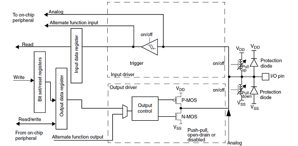
- Note:
- the pull-up and pull-down resistors are disabled (by hardware) in analog mode.
- at reset, all pins are set in analog input mode to protect the device and minimize the power consumption. All unused pins should be kept in this state.
The pin configuration done by the software consists in:
- setting the pin mode in the GPIOx_MODER register:
- input or output if the pin is used as general purpose (GPIO), controlled by software.
- analog.
- alternate function (AF).
- selecting the alternate function in the GPIOx_AFRH/L register (only when the pin mode is AF):
- each IO port can support up to 16 alternate functions that are documented in the datasheet [2].
- setting the pin characteristics:
- no pull-up and no pull-down or pull-up or pull-down in the GPIOx_PUPDR register, needs to be selected to be coherent with the hardware schematics.
- push-pull or open-drain in the GPIOx_OTYPER register, needs to be selected to be coherent with the hardware schematics.
- output speed in the GPIOx_OSPEEDR register needs to be tuned to achieve the expected level of performance (rising and falling times) while limiting electromagnetic interferences (EMI) and overconsumption. As example, the table below summarizes the maximum achievable frequency for each supported IO voltage and a 30pF load:
- On STM32MP13x lines :
- On STM32MP13x lines
GPIOx_OSPEEDR Meaning VDD=3v3 VDD=1v8
HSLV OFFVDD=1v8
HSLV ONb00 Low speed 21 MHz 5 MHz 23 MHz b01 Medium speed 44 MHz 15 MHz 44 MHz b10 High speed 100 MHz 37 MHz 90 MHz b11 Very high speed 166 MHz 50 MHz 133 MHz
- On STM32MP15x lines :
- On STM32MP15x lines
GPIOx_OSPEEDR Meaning VDD=3v3 VDD=1v8
HSLV OFFVDD=1v8
HSLV ONb00 Low speed 24 MHz 11 MHz 22 MHz b01 Medium speed 83 MHz 28 MHz 79 MHz b10 High speed 125 MHz 66 MHz 101 MHz b11 Very high speed 150 MHz 70 MHz 111 MHz
- On STM32MP25x lines :
- On STM32MP25x lines
GPIOx_OSPEEDR Meaning VDD=3v3 VDD=1v8
VRSEL OFFVDD=1v8
VRSEL ONb00 Low speed 45 MHz 20 MHz 45 MHz b01 Medium speed 70 MHz 25 MHz 70 MHz b10 High speed 100 MHz 30 MHz 100 MHz b11 Very high speed 120 MHz 45 MHz 120 MHz
- Notes:
- More information is available in the IO speed settings chapter of the "Getting started with..." [3].
- There are different IO types with different characteristics: for instance, all pads are not able to achieve 150 MHz while supplied at 3.3V. Refer to the datasheet [2] to get the characteristics for each pin.
- On STM32MP1 series, when supplied with VDD=1.8V, it is possible to enable the high speed low voltage (HSLV) pad mode for FTH (Five volt Tolerant High speed) and FTE (Five volt Tolerant Extended high speed) IO types on some peripherals via SYSCFG HSLVEN bits. Warning: As it could be destructive if used when VDD>2.7V, thanks to carefully read the HSLVEN bits documentation in reference manuals [1], especially the management of the OTP bit PRODUCT_BELOW_2V5 (STM32MP1 series) and lock mechanism (for STM32MP13x lines only).
- On STM32MP2 series, IOs could be configured either 1.8V or 3.3V compliance modes.
- In 1.8V mode, IOs are not 3.3V tolerant
- In 3.3V mode, IOs are not 5V tolerant
- By default, all IOs are in 3.3V mode, working in non-optimal condition when supplied with VDD=1.8V. It is responsibility of boot chain to configure IOs mode according to product configuration by setting PWR VRSEL bits for each IO domain.
- Warning: PWR VRSEL bits have effect only if associated HSLV OTP bit have been programmed.
- Warning: Enabling 1.8V mode when VDD=3.3V will damage IOs
The table below shows all possible characteristics combinations for each pin mode:
pin mode GPIOx_PUPDR GPIOx_OTYPER GPIOx_OSPEEDR analog
Not applicable Not applicable Not applicable input (GPIO or AF)
no pull-up and no pull-down
or pull-down
or pull-upNot applicable Not applicable output (GPIO or AF)
or bi-directional (AF)push-pull
or open-draincf. the table above
- Note:
- 'Not applicable' means that setting this register has no effect but, in any case, there is no risk for the device.
- On the other hand, leaving a register not initialized whereas it should be, may lead to an unpredictable behavior!
GPIO access configuration
- On STM32MP13x lines , any IOs from all GPIO banks can be unitary defined as secure or non-secure.
- On STM32MP15x lines , only IOs from GPIOZ can be unitary defined as secure or non-secure.
- On STM32MP25x lines , GPIO are RIF-aware, that means it is possible to assign each GPIO to one execution context define by:
- a security level
- a privilege level
- a CID
- For more information about RIF please refer to Resource Isolation Framework overview.
Refer to the STM32 MPU reference manuals [1] for the complete list of features, and to the software frameworks and drivers, introduced below, to see which features are implemented.
90. Peripheral usage[edit | edit source]
This chapter is applicable in the scope of the OpenSTLinux BSP running on the Arm® Cortex®-A processor(s), and the FwST-M Package running on the Arm® Cortex®-M processor.
90.1. Boot time assignment[edit | edit source]
The STM32CubeMX tool allows to configure in one place the GPIO configuration for boot time and runtime, so it is highly recommended to use it to generate your device tree. Moreover, STM32CubeMX integrates all the information documented in the datasheet [2], making this configuration step straightforward.
Since a GPIO configuration is done via atomic registers read and write, concurrent accesses from different cores must be avoided.
- On STM32MP15x lines all GPIO configurations are done by the Arm® Cortex®-A7.
- On STM32MP25x lines , GPIO configurations could be done by the different execution contexts as soon as RIF configuration has been applied by main processor (TDCID) secure OS.
The strategy is to progressively initialize the GPIO all along the boot chain, as soon as one boot component needs to use them:
- Most of the GPIOs used by the ROM code are directly defined in the ROM code but it is possible to change some pins muxing via dedicated words in BSEC.
- The other boot components are relying on a common binding[4] in the device tree to get the pins configuration:
- The FSBL configures both secure and non-secure pins according to peripherals firewall configuration.
- The Secure OS configures pins firewall protection and secure pins for secure peripherals
- The SSBL and Linux pinctrl only configure non-secure pins.
- On STM32MP15x lines , Linux also initializes the GPIO used by the Cortex-M4 coprocessor, via its resource manager.
- On STM32MP15x lines
90.1.1. On STM32MP13x lines [edit | edit source]
Click on ![]() to expand or collapse the legend...
to expand or collapse the legend...
| Domain | Peripheral | Boot time allocation | Comment | |||
|---|---|---|---|---|---|---|
| Instance | Cortex-A7 secure (ROM code) |
Cortex-A7 secure (TF-A BL2) |
Cortex-A7 nonsecure (U-Boot) | |||
| Core/IOs | GPIO | GPIOA-I | ✓ | ☑ | ☐ | The pins can individually be secured |
90.1.2. On STM32MP15x lines [edit | edit source]
Click on ![]() to expand or collapse the legend...
to expand or collapse the legend...
| Domain | Peripheral | Boot time allocation | Comment | |||
|---|---|---|---|---|---|---|
| Instance | Cortex-A7 secure (ROM code) |
Cortex-A7 secure (TF-A BL2) |
Cortex-A7 nonsecure (U-Boot) | |||
| Core/IOs | GPIO | GPIOA-K | ✓ | ☑ (*) | ☐ | The pins cannot be secured (*): despite they cannot be secured, the pins can be used by the secure context |
| GPIOZ | ☐ | ☐ | The pins can individually be secured | |||
90.1.1. On STM32MP21x lines [edit | edit source]
90.1.1.1. For A35-TD flavor [edit | edit source]
Click on ![]() to expand or collapse the legend...
to expand or collapse the legend...
| Domain | Peripheral | Boot time allocation | Comment | |||
|---|---|---|---|---|---|---|
| Instance | Cortex-A35 secure (ROM code) |
Cortex-A35 secure (TF-A BL2) |
Cortex-A35 nonsecure (U-Boot) | |||
| Core/IOs | GPIO |
GPIOA-I | Shareable at internal peripheral level thanks to the RIF: see the boot time allocation per feature | |||
| GPIOZ | Shareable at internal peripheral level thanks to the RIF: see the boot time allocation per feature | |||||
The below table shows the possible boot time allocations for the features of the GPIOA-I instance.
| Feature | Boot time allocation |
Comment | ||
|---|---|---|---|---|
| Cortex-A35 secure (ROM code) |
Cortex-A35 secure (TF-A BL2) |
Cortex-A35 nonsecure (U-Boot) | ||
| GPIOA-I IOy | ✓ | ☐ | ☐ | |
The below table shows the possible boot time allocations for the features of the GPIOZ instance.
| Feature | Boot time allocation |
Comment | ||
|---|---|---|---|---|
| Cortex-A35 secure (ROM code) |
Cortex-A35 secure (TF-A BL2) |
Cortex-A35 nonsecure (U-Boot) | ||
| GPIOZ IOy | ☐ | ☐ | ||
90.1.1.2. For M33-TD flavor [edit | edit source]
Click on ![]() to expand or collapse the legend...
to expand or collapse the legend...
| Domain | Peripheral | Boot time allocation | Comment | ||||
|---|---|---|---|---|---|---|---|
| Instance | Cortex-A35 secure (ROM code) |
Cortex-A35 secure (TF-A BL2) |
Cortex-A35 nonsecure (U-Boot) |
Cortex-M33 secure (MCUboot) | |||
| Core/IOs | GPIO |
GPIOA-I | Shareable at internal peripheral level thanks to the RIF: see the boot time allocation per feature | ||||
| GPIOZ | Shareable at internal peripheral level thanks to the RIF: see the boot time allocation per feature | ||||||
The below table shows the possible boot time allocations for the features of the GPIOA-I instance.
| Feature | Boot time allocation |
Comment | |||
|---|---|---|---|---|---|
| Cortex-A35 secure (ROM code) |
Cortex-A35 secure (TF-A BL2) |
Cortex-A35 nonsecure (U-Boot) |
Cortex-M33 secure (MCUboot) | ||
| GPIOA-I IOy | ✓ | ☐ | ☐ | ☐ | |
The below table shows the possible boot time allocations for the features of the GPIOZ instance.
| Feature | Boot time allocation |
Comment | |||
|---|---|---|---|---|---|
| Cortex-A35 secure (ROM code) |
Cortex-A35 secure (TF-A BL2) |
Cortex-A35 nonsecure (U-Boot) |
Cortex-M33 secure (MCUboot) | ||
| GPIOZ IOy | ☐ | ☐ | ☐ | ||
90.1.2. On STM32MP23x lines and STM32MP25x lines [edit | edit source]
90.1.2.1. For A35-TD flavor [edit | edit source]
Click on ![]() to expand or collapse the legend...
to expand or collapse the legend...
| Domain | Peripheral | Boot time allocation | Comment | |||
|---|---|---|---|---|---|---|
| Instance | Cortex-A35 secure (ROM code) |
Cortex-A35 secure (TF-A BL2) |
Cortex-A35 nonsecure (U-Boot) | |||
| Core/IOs | GPIO |
GPIOA-K | Shareable at internal peripheral level thanks to the RIF: see the boot time allocation per feature | |||
| GPIOZ | Shareable at internal peripheral level thanks to the RIF: see the boot time allocation per feature | |||||
The below table shows the possible boot time allocations for the features of the GPIOA-K instance.
| Feature | Boot time allocation |
Comment | ||
|---|---|---|---|---|
| Cortex-A35 secure (ROM code) |
Cortex-A35 secure (TF-A BL2) |
Cortex-A35 nonsecure (U-Boot) | ||
| GPIOA-K IOy | ✓ | ☐ | ☐ | |
The below table shows the possible boot time allocations for the features of the GPIOZ instance.
| Feature | Boot time allocation |
Comment | ||
|---|---|---|---|---|
| Cortex-A35 secure (ROM code) |
Cortex-A35 secure (TF-A BL2) |
Cortex-A35 nonsecure (U-Boot) | ||
| GPIOZ IOy | ☐ | ☐ | ||
90.1.2.2. For M33-TD flavor [edit | edit source]
Click on ![]() to expand or collapse the legend...
to expand or collapse the legend...
| Domain | Peripheral | Boot time allocation | Comment | ||||
|---|---|---|---|---|---|---|---|
| Instance | Cortex-A35 secure (ROM code) |
Cortex-A35 secure (TF-A BL2) |
Cortex-A35 nonsecure (U-Boot) |
Cortex-M33 secure (MCUboot) | |||
| Core/IOs | GPIO |
GPIOA-K | Shareable at internal peripheral level thanks to the RIF: see the boot time allocation per feature | ||||
| GPIOZ | Shareable at internal peripheral level thanks to the RIF: see the boot time allocation per feature | ||||||
The below table shows the possible boot time allocations for the features of the GPIOA-K instance.
| Feature | Boot time allocation |
Comment | |||
|---|---|---|---|---|---|
| Cortex-A35 secure (ROM code) |
Cortex-A35 secure (TF-A BL2) |
Cortex-A35 nonsecure (U-Boot) |
Cortex-M33 secure (MCUboot) | ||
| GPIOA-K IOy | ✓ | ☐ | ☐ | ☐ | |
The below table shows the possible boot time allocations for the features of the GPIOZ instance.
| Feature | Boot time allocation |
Comment | |||
|---|---|---|---|---|---|
| Cortex-A35 secure (ROM code) |
Cortex-A35 secure (TF-A BL2) |
Cortex-A35 nonsecure (U-Boot) |
Cortex-M33 secure (MCUboot) | ||
| GPIOZ IOy | ☐ | ☐ | ☐ | ||
90.2. Runtime assignment[edit | edit source]
The GPIO configuration must not be done from different cores to avoid concurrent accesses, but this is not the case for the GPIO using: each core can manipulate IO on its own since dedicated set/clear registers are available for that.
Nevertheless, beyond the boot time, the GPIO configuration also evolves at runtime: while entering in low power mode, some GPIOs may be put back to analog input mode in order to reduce the power consumption.
On STM32MP1 series, this is done in two times:
- the Arm® Cortex®-A non-secure takes care of the non-secure pins with Linux IOs pins frameworks.
- the Arm® Cortex®-A secure takes care of the secure pins.
On wakeup, the boot chain restores the GPIO configuration similarly to what is done at boot time.
On STM32MP25x lines ![]() , thanks to the RIF, each SW component shall take care of its pins during low power entry and exit sequences.
, thanks to the RIF, each SW component shall take care of its pins during low power entry and exit sequences.
90.2.1. On STM32MP13x lines [edit | edit source]
Click on ![]() to expand or collapse the legend...
to expand or collapse the legend...
| Domain | Peripheral | Runtime allocation | Comment | ||
|---|---|---|---|---|---|
| Instance | Cortex-A7 secure (OP-TEE) |
Cortex-A7 nonsecure (Linux) | |||
| Core/IOs | GPIO | GPIOA-I | ☐ | ☐ | The pins can individually be secured |
90.2.2. On STM32MP15x lines [edit | edit source]
Click on ![]() to expand or collapse the legend...
to expand or collapse the legend...
| Domain | Peripheral | Runtime allocation | Comment | |||
|---|---|---|---|---|---|---|
| Instance | Cortex-A7 secure (OP-TEE) |
Cortex-A7 nonsecure (Linux) |
Cortex-M4 (STM32Cube) | |||
| Core/IOs | GPIO | GPIOA-K | ☐ (*) | ☐ | ☐ | The pins can individually be shared (*): despite they cannot be secured, the pins can be used by the secure context |
| GPIOZ | ☐ | ☐ | ☐ | The pins can individually be secured or shared | ||
90.2.1. On STM32MP21x lines [edit | edit source]
The tables below are applicable to any TD flavor (A35-TD or M33-TD) ![]() .
.
Click on ![]() to expand or collapse the legend...
to expand or collapse the legend...
| Domain | Peripheral | Runtime allocation | Comment | ||||
|---|---|---|---|---|---|---|---|
| Instance | Cortex-A35 secure (OP-TEE / TF-A BL31) |
Cortex-A35 nonsecure (Linux) |
Cortex-M33 secure (TF-M) |
Cortex-M33 nonsecure (STM32Cube) | |||
| Core/IOs | GPIO |
GPIOA-I | Shareable at internal peripheral level thanks to the RIF: see the runtime allocation per feature | ||||
| GPIOZ | Shareable at internal peripheral level thanks to the RIF: see the runtime allocation per feature | ||||||
The below table shows the possible runtime allocations for the features of the GPIOA-I instance.
| Feature | Runtime allocation |
Comment | |||
|---|---|---|---|---|---|
| Cortex-A35 secure (OP-TEE / TF-A BL31) |
Cortex-A35 nonsecure (Linux) |
Cortex-M33 secure (TF-M) |
Cortex-M33 nonsecure (STM32Cube) | ||
| GPIOA-I IOy | ☐OP-TEE ☐TF-A BL31 |
☐ | ☐ | ☐ | |
The below table shows the possible runtime allocations for the features of the GPIOZ instance.
| Feature | Runtime allocation |
Comment | |||
|---|---|---|---|---|---|
| Cortex-A35 secure (OP-TEE / TF-A BL31) |
Cortex-A35 nonsecure (Linux) |
Cortex-M33 secure (TF-M) |
Cortex-M33 nonsecure (STM32Cube) | ||
| GPIOZ IOy | ☐OP-TEE ☐TF-A BL31 |
☐ | ☐ | ☐ | |
90.2.2. On STM32MP23x lines [edit | edit source]
The tables below are applicable to any TD flavor (A35-TD or M33-TD) ![]() .
.
Click on ![]() to expand or collapse the legend...
to expand or collapse the legend...
| Domain | Peripheral | Runtime allocation | Comment | ||||
|---|---|---|---|---|---|---|---|
| Instance | Cortex-A35 secure (OP-TEE / TF-A BL31) |
Cortex-A35 nonsecure (Linux) |
Cortex-M33 secure (TF-M) |
Cortex-M33 nonsecure (STM32Cube) | |||
| Core/IOs | GPIO |
GPIOA-K | Shareable at internal peripheral level thanks to the RIF: see the runtime allocation per feature | ||||
| GPIOZ | Shareable at internal peripheral level thanks to the RIF: see the runtime allocation per feature | ||||||
The below table shows the possible runtime allocations for the features of the GPIOA-K instance.
| Feature | Runtime allocation |
Comment | |||
|---|---|---|---|---|---|
| Cortex-A35 secure (OP-TEE / TF-A BL31) |
Cortex-A35 nonsecure (Linux) |
Cortex-M33 secure (TF-M) |
Cortex-M33 nonsecure (STM32Cube) | ||
| GPIOA-K IOy | ☐OP-TEE ☐TF-A BL31 |
☐ | ☐ | ☐ | |
The below table shows the possible runtime allocations for the features of the GPIOZ instance.
| Feature | Runtime allocation |
Comment | |||
|---|---|---|---|---|---|
| Cortex-A35 secure (OP-TEE / TF-A BL31) |
Cortex-A35 nonsecure (Linux) |
Cortex-M33 secure (TF-M) |
Cortex-M33 nonsecure (STM32Cube) | ||
| GPIOZ IOy | ☐OP-TEE ☐TF-A BL31 |
☐ | ☐ | ☐ | |
90.2.3. On STM32MP25x lines [edit | edit source]
The tables below are applicable to any TD flavor (A35-TD or M33-TD) ![]() .
.
Click on ![]() to expand or collapse the legend...
to expand or collapse the legend...
| Domain | Peripheral | Runtime allocation | Comment | |||||
|---|---|---|---|---|---|---|---|---|
| Instance | Cortex-A35 secure (OP-TEE / TF-A BL31) |
Cortex-A35 nonsecure (Linux) |
Cortex-M33 secure (TF-M) |
Cortex-M33 nonsecure (STM32Cube) |
Cortex-M0+ (STM32Cube) | |||
| Core/IOs | GPIO |
GPIOA-K | Shareable at internal peripheral level thanks to the RIF: see the runtime allocation per feature | |||||
| GPIOZ | Shareable at internal peripheral level thanks to the RIF: see the runtime allocation per feature | |||||||
The below table shows the possible runtime allocations for the features of the GPIOA-K instance.
| Feature | Runtime allocation |
Comment | ||||
|---|---|---|---|---|---|---|
| Cortex-A35 secure (OP-TEE / TF-A BL31) |
Cortex-A35 nonsecure (Linux) |
Cortex-M33 secure (TF-M) |
Cortex-M33 nonsecure (STM32Cube) |
Cortex-M0+ (STM32Cube) | ||
| GPIOA-K IOy | ☐OP-TEE ☐TF-A BL31 |
☐ | ☐ | ☐ | - | |
The below table shows the possible runtime allocations for the features of the GPIOZ instance.
| Feature | Runtime allocation |
Comment | ||||
|---|---|---|---|---|---|---|
| Cortex-A35 secure (OP-TEE / TF-A BL31) |
Cortex-A35 nonsecure (Linux) |
Cortex-M33 secure (TF-M) |
Cortex-M33 nonsecure (STM32Cube) |
Cortex-M0+ (STM32Cube) | ||
| GPIOZ IOy | ☐OP-TEE ☐TF-A BL31 |
☐ | ☐ | ☐ | ☐ | |
91. Software frameworks and drivers[edit | edit source]
Below are listed the software frameworks and drivers managing the GPIO peripheral for the embedded software components listed in the above tables.
- Linux®: Linux IOs pins overview
- OP-TEE: GPIO OP-TEE driver and header file of GPIO OP-TEE driver
- STM32Cube: GPIO HAL driver and header file of GPIO HAL module
- TF-A BL2: GPIO driver and header file of GPIO driver
- U-Boot: GPIO driver and header file of GPIO driver
- TF-M: GPIO driver and header file of GPIO driver
92. How to assign and configure the peripheral[edit | edit source]
The peripheral assignment can be done via the STM32CubeMX graphical tool (and manually completed if needed).
This tool also helps to configure the peripheral:
- partial device trees (pin control and clock tree) generation for the OpenSTLinux software components,
- HAL initialization code generation for the STM32CubeMPU Package.
The configuration is applied by the firmware running in the context in which the peripheral is assigned.
In Linux kernel, each GPIO bank is declared as a "gpio-controller" in the device tree and each pin can then be used via two different consumer frameworks:
- Pinctrl framework is used to control the alternate function (AF) selection for a given device driver, via the Pinctrl device tree configuration.
- Gpiolib framework is used to control a pin in GPIO mode from another device driver or a user space application: refer to GPIO device tree configuration for further details.
93. References[edit | edit source]
94. Article purpose[edit | edit source]
The purpose of this article is to:
- briefly introduce the BKPSRAM internal memory peripheral and its main features,
- indicate the peripheral instances assignment at boot time and their assignment at runtime (including whether instances can be allocated to secure contexts),
- list the software frameworks and drivers managing the peripheral,
- explain how to configure the peripheral.
95. Peripheral overview[edit | edit source]
The BKPSRAM internal memory is located in the VSW power domain, allowing it to be supplied during Standby low power mode, or to be switched off.
- STM32MP13x lines BKPSRAM is 8 Kbytes wide.
- STM32MP15x lines BKPSRAM is 4 Kbytes wide.
- STM32MP2 series BKPSRAM is 8 Kbytes wide.
On STM32MP1 series, BKPSRAM could be completely assigned to the different execution contexts thanks to ETZPC firewall.
On STM32MP2 series, BKPSRAM could be shared between the different execution contexts thanks to RISAF firewall.
BKPSRAM is protected by tamper detection circuit and is erased by hardware in case of tamper detection.
Refer to the STM32 MPU reference manuals for the complete list of features, and to the software frameworks and drivers, introduced below, to see which features are implemented.
96. Peripheral usage[edit | edit source]
This chapter is applicable in the scope of the OpenSTLinux BSP running on the Arm® Cortex®-A processor(s), and the STM32CubeMPU Package running on the Arm® Cortex®-M processor.
96.1. Boot time assignment[edit | edit source]
96.1.1. On STM32MP1 series[edit | edit source]
The BKPSRAM internal memory is not used during a cold boot or a wake up from Standby with DDR OFF.
The BKPSRAM internal memory is used by the runtime secure monitor (from the FSBL or the OP-TEE secure OS) during wake-up from Standby low power mode with the DDR in Self-Refresh mode. In that case, the BKPSRAM internal memory contains the secure context that has to be restored before jumping back to Linux execution, in DDR.
Click on ![]() to expand or collapse the legend...
to expand or collapse the legend...
| Domain | Peripheral | Boot time allocation | Comment | |||
|---|---|---|---|---|---|---|
| Instance | Cortex-A7 secure (ROM code) |
Cortex-A7 secure (TF-A BL2) |
Cortex-A7 nonsecure (U-Boot) | |||
| Core/RAM | BKPSRAM | BKPSRAM | ☑ | ⬚ | ||
96.1.2. On STM32MP2 series[edit | edit source]
The BKPSRAM internal memory is not used during a cold boot or a wake up from Standby with DDR OFF.
The BKPSRAM internal memory is used by the runtime secure monitor TF-A BL2 secure monitor during wake-up from Standby low power mode with the DDR in Self-Refresh mode. In that case, the BKPSRAM internal memory contains the secure context that has to be restored before jumping back to OP-TEE secure OS and Linux execution, in DDR.
The BKPSRAM is assigned thanks to RISAF1 configuration that allows sharing and splitting the memory into different regions. It must be done accordingly to the ecosystem usage, as define for:
96.2. Runtime assignment[edit | edit source]
96.2.1. On STM32MP13x lines [edit | edit source]
Click on ![]() to expand or collapse the legend...
to expand or collapse the legend...
| Domain | Peripheral | Runtime allocation | Comment | ||
|---|---|---|---|---|---|
| Instance | Cortex-A7 secure (OP-TEE) |
Cortex-A7 nonsecure (Linux) | |||
| Core/RAM | BKPSRAM | BKPSRAM | ☑ | ⬚ | Assignment (single choice) |
96.2.2. On STM32MP15x lines [edit | edit source]
Click on ![]() to expand or collapse the legend...
to expand or collapse the legend...
| Domain | Peripheral | Runtime allocation | Comment | |||
|---|---|---|---|---|---|---|
| Instance | Cortex-A7 secure (OP-TEE) |
Cortex-A7 nonsecure (Linux) |
Cortex-M4 (STM32Cube) | |||
| Core/RAM | BKPSRAM | BKPSRAM | ☑ | ⬚ | ⬚ | Assignment (single choice) |
96.2.3. On STM32MP2 series[edit | edit source]
The BKPSRAM can be assigned to the different execution contexts thanks to RISAF1 that allows sharing and splitting the memory into different regions. RISAF1 configuration shall be done accordingly to the ecosystem usage, as define for:
97. Software frameworks and drivers[edit | edit source]
97.1. STM32MP1 series[edit | edit source]
On STM32MP1 series, the BKPSRAM peripheral can be allocated to either:
- the Arm® Cortex®-A7 secure to be used by the runtime secure monitor (from the FSBL or the OP-TEE secure OS) to save/restore the secure context before entering/after exiting Standby low power mode with DDR in Self-Refresh mode. Standby low power mode is reached thanks to PSCI [1] secure services (from the FSBL or OP-TEE secure monitor). This is the default assignment.
or
- the Cortex-A7 non-secure to be used under Linux® as reserved memory, for instance.
Thus, below are listed the software frameworks and drivers managing the BKPSRAM peripheral for the embedded software components listed in the above tables.
- Linux®: Linux reserved memory
- OP-TEE: OP-TEE secure monitor
- TF-A BL2: FSBL
- U-Boot: SSBL
97.2. STM32MP2 series[edit | edit source]
Thus, below are listed the software frameworks and drivers managing the BKPSRAM peripheral for the embedded software components listed in the above tables.
- Linux®: Linux reserved memory
- OP-TEE: OP-TEE secure monitor
- TF-A BL2: FSBL
- U-Boot: SSBL
- TF-M: TF-M
98. How to assign and configure the peripheral[edit | edit source]
The peripheral assignment can be done via the STM32CubeMX graphical tool (and manually completed if needed).
This tool also helps to configure the peripheral:
- partial device trees (pin control and clock tree) generation for the OpenSTLinux software components,
- HAL initialization code generation for the STM32CubeMPU Package.
The configuration is applied by the firmware running in the context in which the peripheral is assigned.
99. References[edit | edit source]
100. Article purpose[edit | edit source]
The purpose of this article is to:
- briefly introduce the DDRCTRL and DDRPHYC peripherals and their main features,
- indicate the peripheral instances assignment at boot time and their assignment at runtime (including whether instances can be allocated to secure contexts),
- list the software frameworks and drivers managing the peripherals,
- explain how to configure the peripherals.
101. Peripheral overview[edit | edit source]
The DDRCTRL and DDRPHYC peripherals are used to configure the physical interface to the external DDR memory. Access to the DDR memory can be filtered via the TZC controller on STM32MP1 series or via RISAF on STM32MP2 series.
Notice that it is possible to perform DDR bandwidth measurement thanks to the DDRPERFM internal peripheral.
Refer to the STM32 MPU reference manuals for the complete list of features, and to the software frameworks and drivers, introduced below, to see which features are implemented.
102. Peripheral usage[edit | edit source]
This chapter is applicable in the scope of the OpenSTLinux BSP running on the Arm® Cortex®-A processor(s), and the STM32CubeMPU Package running on the Arm® Cortex®-M processor.
102.1. Boot time assignment[edit | edit source]
The DDRCTRL and DDRPHYC peripherals are kept secure and used by the FSBL to initialize the access to the DDR where it loads the SSBL (U-Boot) for execution.
STMicroelectronics wishes to make the DDR memory configuration as easy as possible, for this reason a dedicated application note has been published by series (for STM32MP1 series [1] and for STM32MP2 series[2]) and a DDR tuning function is available in STM32CubeMX tool in order to generate the device tree configuration that is given to the FSBL to perform this initialization.
102.1.1. On STM32MP1 series[edit | edit source]
Click on ![]() to expand or collapse the legend...
to expand or collapse the legend...
| Domain | Peripheral | Boot time allocation | Comment | |||
|---|---|---|---|---|---|---|
| Instance | Cortex-A7 secure (ROM code) |
Cortex-A7 secure (TF-A BL2) |
Cortex-A7 nonsecure (U-Boot) | |||
| Core/RAM | DDRCTRL | DDR | ☑ | ⬚ | ||
102.1.2. On STM32MP2 series[edit | edit source]
102.1.2.1. For A35-TD flavor [edit | edit source]
Click on ![]() to expand or collapse the legend...
to expand or collapse the legend...
| Domain | Peripheral | Boot time allocation | Comment | |||
|---|---|---|---|---|---|---|
| Instance | Cortex-A35 secure (ROM code) |
Cortex-A35 secure (TF-A BL2) |
Cortex-A35 nonsecure (U-Boot) | |||
| Core/RAM | DDRCTRL & DDRPHYC | DDR | ✓ | ⬚ | Assignment is controlled by the RCC RIF 104 resource that also include the PLL2 control. | |
102.1.2.2. For M33-TD flavor [edit | edit source]
Click on ![]() to expand or collapse the legend...
to expand or collapse the legend...
| Domain | Peripheral | Boot time allocation | Comment | ||||
|---|---|---|---|---|---|---|---|
| Instance | Cortex-A35 secure (ROM code) |
Cortex-A35 secure (TF-A BL2) |
Cortex-A35 nonsecure (U-Boot) |
Cortex-M33 secure (MCUboot) | |||
| Core/RAM | DDRCTRL & DDRPHYC | DDR | ✓ | Assignment is controlled by the RCC RIF 104 resource that also include the PLL2 control. | |||
102.2. Runtime assignment[edit | edit source]
The DDRCTRL and DDRPHYC peripherals are accessed at runtime by the secure world of the cold boot CPU (see the Boot chain overview for details) to put the DDR in self-refresh state before going into Stop or Standby low power mode:
- On STM32MP13x lines , OP-TEE is default located in DDR and it jumps into TF-A BL2 resident code in SYSRAM to configure the DDRCTRL and DDRPHYC
- On STM32MP15x lines , OP-TEE is either located in SYSRAM (with CFG_STM32MP1_OPTEE_IN_SYSRAM=y, so it embeds the services to configure the DDRCTRL and DDRPHYC) or in DDR (see previous STM32MP13x lines case)
- On STM32MP2 series,
- for A35-TD flavor : TF-A BL31 secure monitor is running in SYSRAM and configure the DDRCTRL and DDRPHYC after low power request
- for M33-TD flavor : the low power firmware is running in RETRAM and configure the DDRCTRL and DDRPHYC
- for A35-TD flavor
On Standby exit, the ROM code loads the FSBL-A that again configures the DDRCTRL and DDRPHYC before proceeding with the wake-up procedure or for M33-TD flavor ![]() jump in the RETRAM low power firmware.
jump in the RETRAM low power firmware.
DDR memory access is controlled by:
102.2.1. On STM32MP13x lines [edit | edit source]
Click on ![]() to expand or collapse the legend...
to expand or collapse the legend...
| Domain | Peripheral | Runtime allocation | Comment | ||
|---|---|---|---|---|---|
| Instance | Cortex-A7 secure (OP-TEE) |
Cortex-A7 nonsecure (Linux) | |||
| Core/RAM | DDRCTRL | DDR | ☑ | ⬚ | |
102.2.2. On STM32MP15x lines [edit | edit source]
Click on ![]() to expand or collapse the legend...
to expand or collapse the legend...
| Domain | Peripheral | Runtime allocation | Comment | |||
|---|---|---|---|---|---|---|
| Instance | Cortex-A7 secure (OP-TEE) |
Cortex-A7 nonsecure (Linux) |
Cortex-M4 (STM32Cube) | |||
| Core/RAM | DDRCTRL | DDR | ☑ | ⬚ | ||
102.2.3. On STM32MP21x lines and STM32MP23x lines [edit | edit source]
102.2.3.1. For A35-TD flavor [edit | edit source]
Click on ![]() to expand or collapse the legend...
to expand or collapse the legend...
| Domain | Peripheral | Runtime allocation | Comment | ||||
|---|---|---|---|---|---|---|---|
| Instance | Cortex-A35 secure (OP-TEE / TF-A BL31) |
Cortex-A35 nonsecure (Linux) |
Cortex-M33 secure (TF-M) |
Cortex-M33 nonsecure (STM32Cube) | |||
| Core/RAM | DDRCTRL & DDRPHYC | DDR | ✓OP-TEE ✓TF-A BL31 |
⬚ | ☐ | ⬚ | Assignment is controlled by the RCC RIF 104 resource that also include the PLL2 control. |
102.2.3.2. For M33-TD flavor [edit | edit source]
Click on ![]() to expand or collapse the legend...
to expand or collapse the legend...
| Domain | Peripheral | Runtime allocation | Comment | ||||
|---|---|---|---|---|---|---|---|
| Instance | Cortex-A35 secure (OP-TEE / TF-A BL31) |
Cortex-A35 nonsecure (Linux) |
Cortex-M33 secure (TF-M) |
Cortex-M33 nonsecure (STM32Cube) | |||
| Core/RAM | DDRCTRL & DDRPHYC | DDR | ✓ | ⬚ | Assignment is controlled by the RCC RIF 104 resource that also include the PLL2 control. | ||
102.2.4. On STM32MP25x lines [edit | edit source]
102.2.4.1. For A35-TD flavor [edit | edit source]
Click on ![]() to expand or collapse the legend...
to expand or collapse the legend...
| Domain | Peripheral | Runtime allocation | Comment | |||||
|---|---|---|---|---|---|---|---|---|
| Instance | Cortex-A35 secure (OP-TEE / TF-A BL31) |
Cortex-A35 nonsecure (Linux) |
Cortex-M33 secure (TF-M) |
Cortex-M33 nonsecure (STM32Cube) |
Cortex-M0+ (STM32Cube) | |||
| Core/RAM | DDRCTRL & DDRPHYC | DDR | ✓OP-TEE ✓TF-A BL31 |
⬚ | ☐ | ⬚ | Assignment is controlled by the RCC RIF 104 resource that also include the PLL2 control. | |
102.2.4.2. For M33-TD flavor [edit | edit source]
Click on ![]() to expand or collapse the legend...
to expand or collapse the legend...
| Domain | Peripheral | Runtime allocation | Comment | |||||
|---|---|---|---|---|---|---|---|---|
| Instance | Cortex-A35 secure (OP-TEE / TF-A BL31) |
Cortex-A35 nonsecure (Linux) |
Cortex-M33 secure (TF-M) |
Cortex-M33 nonsecure (STM32Cube) |
Cortex-M0+ (STM32Cube) | |||
| Core/RAM | DDRCTRL & DDRPHYC | DDR | ✓ | ⬚ | Assignment is controlled by the RCC RIF 104 resource that also include the PLL2 control. | |||
103. Software frameworks and drivers[edit | edit source]
Below are listed the software frameworks and drivers managing the DDRCTRL and DDRPHYC peripherals for the embedded software components (mainly low power sequences, initialization is always handled by TF-A BL2).
103.1. On STM32MP13x lines [edit | edit source]
- TF-A BL2:
- drivers/st/ddr/ (files with stm32mp1_ and stm32mp_ prefixes)
103.2. On STM32MP15x lines [edit | edit source]
- TF-A BL2:
- drivers/st/ddr/ (files with stm32mp1_ and stm32mp_ prefixes)
- OP-TEE: (if OP-TEE is in SYSRAM with STM32MP1_OPTEE_IN_SYSRAM)
103.3. On STM32MP2 series[edit | edit source]
- TF-A BL2:
- drivers/st/ddr/ ((files with stm32mp2_ and stm32mp_ prefixes)
- drivers/st/ddr/phy/phyinit/src/
- drivers/st/ddr/phy/phyinit/usercustom/
- TF-M:
- DDR FW binary <ddr_type>_pmu_train.bin is present in TF-A directory drivers/st/ddr/phy/firmware/bin/stm32mp2/ and in GIT repository: https://github.com/STMicroelectronics/stm32-ddr-phy-binary
104. How to assign and configure the peripheral[edit | edit source]
The DDRCTRL and DDRPHYC device tree configuration is generated via STM32CubeMX tool, according to the DDR characteristics (type, size, frequency, speed grade). This configuration is applied during boot time by the FSBL (see boot chain overview).
105. References[edit | edit source]
106. Article purpose[edit | edit source]
The purpose of this article is to:
- briefly introduce the RETRAM internal memory peripheral and its main features,
- indicate the peripheral instances assignment at boot time and their assignment at runtime (including whether instances can be allocated to secure contexts),
- list the software frameworks and drivers managing the peripheral,
- explain how to configure the peripheral.
107. Peripheral overview[edit | edit source]
The RETRAM internal memory is located in the VSW power domain, allowing it to be supplied during Standby low power mode, and to retain retention firmware or data in Standby mode.
107.1. STM32MP15x lines [edit | edit source]
On STM32MP15x lines ![]() , the RETRAM internal memory is 64 Kbytes wide and is physically near to the Arm® Cortex®-M4 for optimized performance from the core and to execute very quickly by the Cortex-M4 on wake up from Standby mode.
, the RETRAM internal memory is 64 Kbytes wide and is physically near to the Arm® Cortex®-M4 for optimized performance from the core and to execute very quickly by the Cortex-M4 on wake up from Standby mode.
The Cortex-M4 firmware has to be loaded to the RETRAM , starting at address 0x00000000. At least, it must load the part of the firmware containing the vector table, since the Arm® Cortex®-M4 reset entry point is address 0x00000004. The rest of the firmware code is loaded into the MCU SRAM. The overall memory mapping is shown in the platform memory mapping section.
While going to Standby low power mode, the RETRAM can remain supplied, so it can preserve a (small) Arm® Cortex®-M4 piece of retention firmware that is executed on wake up when the ROM code (running on Arm® Cortex®-A7) restarts the Arm® Cortex®-M4.
107.2. STM32MP2 series[edit | edit source]
On STM32MP2 series, the RETRAM internal memory is 128 Kbytes wide and mainly dedicated to the Arm® Cortex®-M33 for autonomous wakeup from low power Standby mode.
The Cortex-M33 firmware with low power functions has to be loaded to the "RETRAM" with associated reference CRC by the main processor (TDCID) following the procedure described in the SRAM configuration controller (RAMCFG) chapter of STM32MP25 reference manuals.
On Standby exit, in case of wake up event assigned to Arm® Cortex®-M33, the SoC will verify the RETRAM integrity thanks to associated HW ECC and then the Cortex-M33 firmware integrity by checking CRC. In case of success, the SoC will start Cortex-M33 at start address of the RETRAM. Else an error will be generated and sent to main processor or a system reset generated according to system configuration.
Moreover RETRAM is protected by a RISAB memory firewall which allows to define some memory regions with different access rights with a 4kB granularity. Each region can be assigned to the different execution contexts of the plateform.
Refer to the STM32 MPU reference manuals for the complete list of features, and to the software frameworks and drivers, introduced below, to see which features are implemented.
108. Peripheral usage[edit | edit source]
This chapter is applicable in the scope of the OpenSTLinux BSP running on the Arm® Cortex®-A processor(s), and the STM32CubeMPU Package running on the Arm® Cortex®-M processor.
108.1. Boot time assignment[edit | edit source]
108.1.1. On STM32MP15x lines [edit | edit source]
At boot time, The RETRAM internal memory can contain the Arm® Cortex®-M4 firmware, but could also be dedicated to some other usages.
Click on ![]() to expand or collapse the legend...
to expand or collapse the legend...
| Domain | Peripheral | Boot time allocation | Comment | |||
|---|---|---|---|---|---|---|
| Instance | Cortex-A7 secure (ROM code) |
Cortex-A7 secure (TF-A BL2) |
Cortex-A7 nonsecure (U-Boot) | |||
| Core/RAM | RETRAM | RETRAM | ☐ | |||
108.1.2. On STM32MP2 series[edit | edit source]
The RETRAM is assigned thanks to RISAB configuration that allows sharing and splitting the memory into different regions. It must be done accordingly to the ecosystem usage, as define for:
108.2. Runtime assignment[edit | edit source]
108.2.1. On STM32MP15x lines [edit | edit source]
At runtime the RETRAM can be allocated to:
- the Arm® Cortex®-M4 (default) for use with the STM32Cube MPU Package, either for runtime firmware that can be mapped in both RETRAM and MCU SRAM, or for retention firmware that only fits into the RETRAM ,
or
- the Arm® Cortex®-A7 secure to be used under OP-TEE,
or
- the Arm® Cortex®-A7 non-secure to be used under Linux as reserved memory.
Click on ![]() to expand or collapse the legend...
to expand or collapse the legend...
| Domain | Peripheral | Runtime allocation | Comment | |||
|---|---|---|---|---|---|---|
| Instance | Cortex-A7 secure (OP-TEE) |
Cortex-A7 nonsecure (Linux) |
Cortex-M4 (STM32Cube) | |||
| Core/RAM | RETRAM | RETRAM | ⬚ | ⬚ | ☑ | Assignment to the Arm® Cortex®-M4 if used |
108.2.2. On STM32MP2 series[edit | edit source]
The RETRAM is assigned thanks to RISAB configuration that allows sharing and splitting the memory into different regions. It must be done accordingly to the ecosystem usage, as define for:
109. Software frameworks and drivers[edit | edit source]
The RETRAM is the minimum (and default) memory for the Arm® Cortex®-M4 firmware.The software frameworks and component managing the RETRAM device to host the Arm® Cortex®-M4 firmware are listed below.
- Linux®: Linux reserved memory and Linux remoteproc framework
- OP-TEE: OP-TEE remoteproc source code
- STM32Cube: STM32CubeMP15 Package and STM32CubeMP2 Package
- TF-M:TF-M overview
110. How to assign and configure the peripheral[edit | edit source]
The peripheral assignment can be done via the STM32CubeMX graphical tool (and manually completed if needed).
This tool also helps to configure the peripheral:
- partial device trees (pin control and clock tree) generation for the OpenSTLinux software components,
- HAL initialization code generation for the STM32CubeMPU Package.
The configuration is applied by the firmware running in the context in which the peripheral is assigned.
111. Article purpose[edit | edit source]
The purpose of this article is to:
- briefly introduce the SYSRAM internal memory peripheral and its main features,
- indicate the peripheral instances assignment at boot time and their assignment at runtime (including whether instances can be allocated to secure contexts),
- list the software frameworks and drivers managing the peripheral,
- explain how to configure the peripheral.
112. Peripheral overview[edit | edit source]
The SYSRAM peripheral is an internal memory peripheral. It is physically located near the Arm® Cortex-A to optimize the core performance.
- STM32MP13x lines SYSRAM is 128-Kbyte wide
- STM32MP15x lines SYSRAM is 256-Kbyte wide
- STM32MP2 series SYSRAM is 256-Kbyte wide
On STM32MP1 series, the SYSRAM is protected by ETZPC firewall. By default, SYSRAM access is granted to Cortex-A7 secure. The SYSRAM can be split into 2 memory regions with a 4-Kbyte granularity:
- a low secure region
- a high non-secure region
On STM32MP2 series, the SYSRAM is protected by RISAB memory firewall, allowing to create some 4-Kbyte granularity memory regions with different access rights to share SYSRAM between the different execution contexts of the platform. By default, SYSRAM access is granted to Cortex-A35 secure and can be only configured by Cortex-A35 secure.
Refer to the STM32 MPU reference manuals for the complete list of features, and to the software frameworks and drivers, introduced below, to see which features are implemented.
113. Peripheral usage[edit | edit source]
This chapter is applicable in the scope of the OpenSTLinux BSP running on the Arm® Cortex®-A processor(s), and the STM32CubeMPU Package running on the Arm® Cortex®-M processor.
113.1. Boot time assignment[edit | edit source]
113.1.1. On STM32MP13x lines [edit | edit source]
The ROM code leaves the SYSRAM secure when it jumps to the entry point of the FSBL that it has just loaded into the SYSRAM.
The FSBL does not have to keep any context in SYSRAM when it jumps to the SSBL: each boot stage is independent from the other.
Click on ![]() to expand or collapse the legend...
to expand or collapse the legend...
| Domain | Peripheral | Boot time allocation | Comment | |||
|---|---|---|---|---|---|---|
| Instance | Cortex-A7 secure (ROM code) |
Cortex-A7 secure (TF-A BL2) |
Cortex-A7 nonsecure (U-Boot) | |||
| Core/RAM | SYSRAM | SYSRAM | ✓ | ✓ | ||
113.1.2. On STM32MP15x lines [edit | edit source]
The ROM code mainly configures the SYSRAM as a secure peripheral during its execution. It uses 9 Kbytes located at the beginning of the SYSRAM to store its read and write data. Among them, it stores the boot context in the first 512 bytes of SYSRAM: this boot context contains several information (such as the selected boot device) and pointers to the ROM code exported services (used for secure boot authentication). The ROM code loads the FSBL just after the boot context, into the remaining 247 Kbytes of SYSRAM, and eventually branches the Cortex®-A7 core 0 execution to this FSBL.
The FSBL code can use the whole SYSRAM, but it must take care not to overwrite the boot context before taking it into account.
Click on ![]() to expand or collapse the legend...
to expand or collapse the legend...
| Domain | Peripheral | Boot time allocation | Comment | |||
|---|---|---|---|---|---|---|
| Instance | Cortex-A7 secure (ROM code) |
Cortex-A7 secure (TF-A BL2) |
Cortex-A7 nonsecure (U-Boot) | |||
| Core/RAM | SYSRAM | SYSRAM | ✓ | ✓ | ||
113.1.3. On STM32MP2 series[edit | edit source]
The ROM code leaves the SYSRAM secure when it jumps to the entry point of the FSBL that it has just loaded into the SYSRAM.
The FSBL does not have to keep any context in SYSRAM when it jumps to the next boot stages: each boot stage is independent from the other.
113.1.3.1. For A35-TD flavor [edit | edit source]
Click on ![]() to expand or collapse the legend...
to expand or collapse the legend...
| Domain | Peripheral | Boot time allocation | Comment | |||
|---|---|---|---|---|---|---|
| Instance | Cortex-A35 secure (ROM code) |
Cortex-A35 secure (TF-A BL2) |
Cortex-A35 nonsecure (U-Boot) | |||
| Core/RAM | SYSRAM | SYSRAM | ✓ | ✓ | ||
113.1.3.2. For M33-TD flavor [edit | edit source]
Click on ![]() to expand or collapse the legend...
to expand or collapse the legend...
| Domain | Peripheral | Boot time allocation | Comment | ||||
|---|---|---|---|---|---|---|---|
| Instance | Cortex-A35 secure (ROM code) |
Cortex-A35 secure (TF-A BL2) |
Cortex-A35 nonsecure (U-Boot) |
Cortex-M33 secure (MCUboot) | |||
| Core/RAM | SYSRAM | SYSRAM | ✓ | ✓ | |||
113.2. Runtime assignment[edit | edit source]
113.2.1. On STM32MP13x lines [edit | edit source]
In OSTL distribution, the SYSRAM runtime mapping is the one reached at the end of the boot. It is consequently fully secure and can contain a secure monitor functions provided by OP-TEE secure OS to handle low power modes.
STM32MP13 embeds an on-the-fly DDR cyphering engine, the DDRMCE internal peripheral, allowing to put OP-TEE secure OS sensitive code inside the external DDR, instead of the SYSRAM.
You may decide to split the SYSRAM at runtime. In this case:
- set the SYSRAM bottom secure, for a Cortex®-A7 secure monitor or a secure OS (such as OP-TEE)
and
- set the SYSRAM top non-secure, for instance for using in Linux® as reserved memory
Click on ![]() to expand or collapse the legend...
to expand or collapse the legend...
| Domain | Peripheral | Runtime allocation | Comment | ||
|---|---|---|---|---|---|
| Instance | Cortex-A7 secure (OP-TEE) |
Cortex-A7 nonsecure (Linux) | |||
| Core/RAM | SYSRAM | SYSRAM | ☑ | ☐ | Shareable (multiple choices supported)
Secure section required for low power entry and exit |
113.2.2. On STM32MP15x lines [edit | edit source]
In OSTL distribution, the SYSRAM runtime mapping is the one reached at the end of the boot. It is consequently fully secure and can contain a secure OS (like OP-TEE).
You may decide to split the SYSRAM at runtime. In this case:
- set the SYSRAM bottom secure, for a Cortex®-A7 secure monitor or a secure OS (such as OP-TEE)
and
- set the SYSRAM top non-secure, for instance for using in Linux® as reserved memory
Click on ![]() to expand or collapse the legend...
to expand or collapse the legend...
| Domain | Peripheral | Runtime allocation | Comment | |||
|---|---|---|---|---|---|---|
| Instance | Cortex-A7 secure (OP-TEE) |
Cortex-A7 nonsecure (Linux) |
Cortex-M4 (STM32Cube) | |||
| Core/RAM | SYSRAM | SYSRAM | ☑ | ☐ | ⬚ | Shareable (multiple choices supported)
Secure section required for low power entry and exit |
113.2.3. On STM32MP21x lines [edit | edit source]
The tables below are applicable to any TD flavor (A35-TD or M33-TD) ![]() .
.
In OSTL distribution, the SYSRAM runtime mapping is split into two regions.
- one Cortex-A35 secure region dedicated to secure monitor which handles Cortex-A35 cluster
- one Cortex-A35 non-secure region assigned to Linux kernel for HPDMA linked list management
As SYSRAM is used by ROM code during D1Standby exit low power sequence, it is not recommended to assign SYSRAM to Cortex-M33 except if product doesn't plan to support Run2 and (LPLV)Stop2 low power modes.
Click on ![]() to expand or collapse the legend...
to expand or collapse the legend...
| Domain | Peripheral | Runtime allocation | Comment | ||||
|---|---|---|---|---|---|---|---|
| Instance | Cortex-A35 secure (OP-TEE / TF-A BL31) |
Cortex-A35 nonsecure (Linux) |
Cortex-M33 secure (TF-M) |
Cortex-M33 nonsecure (STM32Cube) | |||
| Core/RAM | SYSRAM | SYSRAM | ☑BL31 ☐OP-TEE |
☑ | ☐ | ☐ |
Cortex-A35 secure section required for low power entry and exit |
113.2.4. On STM32MP23x lines [edit | edit source]
The tables below are applicable to any TD flavor (A35-TD or M33-TD) ![]() .
.
In OSTL distribution, the SYSRAM runtime mapping is split into two regions.
- one Cortex-A35 secure region dedicated to secure monitor which handles Cortex-A35 cluster
- one Cortex-A35 non-secure region assigned to Linux kernel for HPDMA linked list management
As SYSRAM is used by ROM code during D1Standby exit low power sequence, it is not recommended to assign SYSRAM to Cortex-M33 except if product doesn't plan to support Run2 and (LPLV)Stop2 low power modes.
Click on ![]() to expand or collapse the legend...
to expand or collapse the legend...
| Domain | Peripheral | Runtime allocation | Comment | ||||
|---|---|---|---|---|---|---|---|
| Instance | Cortex-A35 secure (OP-TEE / TF-A BL31) |
Cortex-A35 nonsecure (Linux) |
Cortex-M33 secure (TF-M) |
Cortex-M33 nonsecure (STM32Cube) | |||
| Core/RAM | SYSRAM | SYSRAM | ☑BL31 ☐OP-TEE |
☑ | ☐ | ☐ |
Cortex-A35 secure section required for low power entry and exit |
113.2.5. On STM32MP25x lines [edit | edit source]
The tables below are applicable to any TD flavor (A35-TD or M33-TD) ![]() .
.
In OSTL distribution, the SYSRAM runtime mapping is split into two regions.
- one Cortex-A35 secure region dedicated to secure monitor which handles Cortex-A35 cluster
- one Cortex-A35 non-secure region assigned to Linux kernel for HPDMA linked list management
As SYSRAM is used by ROM code during D1Standby exit low power sequence, it is not recommended to assign SYSRAM to Cortex-M33 except if product doesn't plan to support Run2 and (LPLV)Stop2 low power modes.
Click on ![]() to expand or collapse the legend...
to expand or collapse the legend...
| Domain | Peripheral | Runtime allocation | Comment | |||||
|---|---|---|---|---|---|---|---|---|
| Instance | Cortex-A35 secure (OP-TEE / TF-A BL31) |
Cortex-A35 nonsecure (Linux) |
Cortex-M33 secure (TF-M) |
Cortex-M33 nonsecure (STM32Cube) |
Cortex-M0+ (STM32Cube) | |||
| Core/RAM | SYSRAM | SYSRAM | ☑BL31 ☐OP-TEE |
☑ | ☐ | ☐ |
Cortex-A35 secure section required for low power entry and exit | |
114. Software frameworks and drivers[edit | edit source]
Thus, below are listed the software frameworks and drivers managing the XXX peripheral for the embedded software components listed in the above tables.
- Linux®: Linux reserved memory
- OP-TEE: OP-TEE
- TF-A BL2: TF-A BL2
- TF-A BL31: TF-A BL31
- TF-M: TF-M
115. How to assign and configure the peripheral[edit | edit source]
The peripheral assignment can be done via the STM32CubeMX graphical tool (and manually completed if needed).
This tool also helps to configure the peripheral:
- partial device trees (pin control and clock tree) generation for the OpenSTLinux software components,
- HAL initialization code generation for the STM32CubeMPU Package.
The configuration is applied by the firmware running in the context in which the peripheral is assigned.
116. Article purpose[edit | edit source]
The purpose of this article is to:
- briefly introduce the LPTIM peripheral and its main features,
- indicate the peripheral instances assignment at boot time and their assignment at runtime (including whether instances can be allocated to secure contexts),
- list the software frameworks and drivers managing the peripheral,
- explain how to configure the peripheral.
117. Peripheral overview[edit | edit source]
The LPTIM peripheral is a single channel low-power timer unit, that can continue to run even during low power modes when it selects a clock source that remains active in RCC.
The LPTIM peripheral is available in different configurations. Depending on the selected instance, it can act as PWM, quadrature encoder[1], external event counter or trigger source for other internal peripherals, like ADC, DAC and DFSDM (on STM32MP1 series) or MDF (on STM32MP2 series).
- LPTIM on STM32MP1 series
| LPTIM instances | Independent Channels | PWM | External event counter Trigger source |
Quadrature encoder |
|---|---|---|---|---|
| LPTIM1, LPTIM2 | 1 | |||
| LPTIM3 | 1 | |||
| LPTIM4, LPTIM5 | 1 |
- LPTIM on STM32MP2 series
| LPTIM instances | Independent Channels | PWM | External event counter Trigger source |
Quadrature encoder |
|---|---|---|---|---|
| LPTIM1, LPTIM2 | 2 | |||
| LPTIM3, LPTIM4 | 2 | |||
| LPTIM5 | 1 |
- On STM32MP13x lines , LPTIM3 can be used for RCC HSE clock source monitoring.
- On STM32MP2 series, LPTIM can have up to 2 independent channels. It also supports input capture. LPTIM1 can be used for RCC HSE monitoring.
Refer to the STM32 MPU reference manuals for the complete list of features, and to the software frameworks and drivers, introduced below, to see which features are implemented.
118. Peripheral usage[edit | edit source]
This chapter is applicable in the scope of the OpenSTLinux BSP running on the Arm® Cortex®-A processor(s), and the FwST-M Package running on the Arm® Cortex®-M processor.
118.1. Boot time assignment[edit | edit source]
118.1.1. On STM32MP13x lines [edit | edit source]
Click on ![]() to expand or collapse the legend...
to expand or collapse the legend...
| Domain | Peripheral | Boot time allocation | Comment | |||
|---|---|---|---|---|---|---|
| Instance | Cortex-A7 secure (ROM code) |
Cortex-A7 secure (TF-A BL2) |
Cortex-A7 nonsecure (U-Boot) | |||
| Core/Timers | LPTIM | LPTIM1 | ⬚ | |||
| LPTIM2 | ⬚ | ⬚ | ||||
| LPTIM3 | ⬚ | ⬚ | ||||
| LPTIM4 | ⬚ | |||||
| LPTIM5 | ⬚ | |||||
118.1.2. On STM32MP15x lines [edit | edit source]
Click on ![]() to expand or collapse the legend...
to expand or collapse the legend...
| Domain | Peripheral | Boot time allocation | Comment | |||
|---|---|---|---|---|---|---|
| Instance | Cortex-A7 secure (ROM code) |
Cortex-A7 secure (TF-A BL2) |
Cortex-A7 nonsecure (U-Boot) | |||
| Core/Timers | LPTIM | LPTIMx (x = 1 to 5) | ⬚ | LPTIM are not used at boot time. | ||
118.1.3. On STM32MP2 series[edit | edit source]
118.1.3.1. For A35-TD flavor [edit | edit source]
Click on ![]() to expand or collapse the legend...
to expand or collapse the legend...
| Domain | Peripheral | Boot time allocation | Comment | |||
|---|---|---|---|---|---|---|
| Instance | Cortex-A35 secure (ROM code) |
Cortex-A35 secure (TF-A BL2) |
Cortex-A35 nonsecure (U-Boot) | |||
| Core/Timers | LPTIM | LPTIMx (x = 1 to 5) | ⬚ | ⬚ | ||
118.1.3.2. For M33-TD flavor [edit | edit source]
Click on ![]() to expand or collapse the legend...
to expand or collapse the legend...
| Domain | Peripheral | Boot time allocation | Comment | ||||
|---|---|---|---|---|---|---|---|
| Instance | Cortex-A35 secure (ROM code) |
Cortex-A35 secure (TF-A BL2) |
Cortex-A35 nonsecure (U-Boot) |
Cortex-M33 secure (MCUboot) | |||
| Core/Timers | LPTIM | LPTIMx (x = 1 to 5) | ⬚ | ⬚ | ⬚ | ||
118.2. Runtime assignment[edit | edit source]
118.2.1. On STM32MP13x lines [edit | edit source]
Click on ![]() to expand or collapse the legend...
to expand or collapse the legend...
| Domain | Peripheral | Runtime allocation | Comment | ||
|---|---|---|---|---|---|
| Instance | Cortex-A7 secure (OP-TEE) |
Cortex-A7 nonsecure (Linux) | |||
| Core/Timers | LPTIM | LPTIM1 | ☐ | ||
| LPTIM2 | ☐ | ☐ | Assignment (single choice) | ||
| LPTIM3 | ☐ | ☐ | Assignment (single choice) LPTIM3 can be used for HSE monitoring. | ||
| LPTIM4 | ☐ | ||||
| LPTIM5 | ☐ | ||||
118.2.2. On STM32MP15x lines [edit | edit source]
Click on ![]() to expand or collapse the legend...
to expand or collapse the legend...
| Domain | Peripheral | Runtime allocation | Comment | |||
|---|---|---|---|---|---|---|
| Instance | Cortex-A7 secure (OP-TEE) |
Cortex-A7 nonsecure (Linux) |
Cortex-M4 (STM32Cube) | |||
| Core/Timers | LPTIM | LPTIMx (x = 1 to 5) | ☐ | ☐ | Assignment (single choice) | |
118.2.3. On STM32MP21x lines and STM32MP23x lines [edit | edit source]
The tables below are applicable to any TD flavor (A35-TD or M33-TD) ![]() .
.
Click on ![]() to expand or collapse the legend...
to expand or collapse the legend...
| Domain | Peripheral | Runtime allocation | Comment | ||||
|---|---|---|---|---|---|---|---|
| Instance | Cortex-A35 secure (OP-TEE / TF-A BL31) |
Cortex-A35 nonsecure (Linux) |
Cortex-M33 secure (TF-M) |
Cortex-M33 nonsecure (STM32Cube) | |||
| Core/Timers | LPTIM | LPTIM1 | ☐OP-TEE | ☐ | ⬚ | ☐ | LPTIM1 can be used for HSE monitoring. |
| LPTIM2 | ☐OP-TEE | ☐ | ⬚ | ☐ | |||
| LPTIM3 | ☐OP-TEE | ☐ | ⬚ | ☐ | LPTIMy (y = 3, 4, 5) can be used for scheduling in low power modes by Linux | ||
| LPTIM4 | ☐OP-TEE | ☐ | ⬚ | ☐ | LPTIMy (y = 3, 4, 5) can be used for scheduling in low power modes by Linux | ||
| LPTIM5 | ☐OP-TEE | ☐ | ⬚ | ☐ | LPTIMy (y = 3, 4, 5) can be used for scheduling in low power modes by Linux | ||
118.2.4. On STM32MP25x lines [edit | edit source]
The tables below are applicable to any TD flavor (A35-TD or M33-TD) ![]() .
.
Click on ![]() to expand or collapse the legend...
to expand or collapse the legend...
| Domain | Peripheral | Runtime allocation | Comment | |||||
|---|---|---|---|---|---|---|---|---|
| Instance | Cortex-A35 secure (OP-TEE / TF-A BL31) |
Cortex-A35 nonsecure (Linux) |
Cortex-M33 secure (TF-M) |
Cortex-M33 nonsecure (STM32Cube) |
Cortex-M0+ (STM32Cube) | |||
| Core/Timers | LPTIM | LPTIM1 | ☐OP-TEE | ☐ | ⬚ | ☐ | LPTIM1 can be used for HSE monitoring. | |
| LPTIM2 | ☐OP-TEE | ☐ | ⬚ | ☐ | ||||
| LPTIM3 | ☐OP-TEE | ☐ | ⬚ | ☐ | ☐ | LPTIMy (y = 3, 4, 5) can be used for scheduling in low power modes by Linux | ||
| LPTIM4 | ☐OP-TEE | ☐ | ⬚ | ☐ | ☐ | LPTIMy (y = 3, 4, 5) can be used for scheduling in low power modes by Linux | ||
| LPTIM5 | ☐OP-TEE | ☐ | ⬚ | ☐ | ☐ | LPTIMy (y = 3, 4, 5) can be used for scheduling in low power modes by Linux | ||
119. Software frameworks and drivers[edit | edit source]
Below are listed the software frameworks and drivers managing the LPTIM peripheral for the embedded software components listed in the above tables.
- Linux®: PWM framework, IIO framework, Counter framework, and Clock events framework, LPTIM OpenSTLinux drivers
- OP-TEE: OP-TEE LPTIM driver
- STM32Cube: HAL LPTIM driver
120. How to assign and configure the peripheral[edit | edit source]
The peripheral assignment can be done via the STM32CubeMX graphical tool (and manually completed if needed).
This tool also helps to configure the peripheral:
- partial device trees (pin control and clock tree) generation for the OpenSTLinux software components,
- HAL initialization code generation for the STM32CubeMPU Package.
The configuration is applied by the firmware running in the context in which the peripheral is assigned.
For Linux kernel configuration, please refer to LPTIM device tree configuration and STM32 LPTIM Linux driver articles.
121. References[edit | edit source]
122. Article purpose[edit | edit source]
The purpose of this article is to:
- briefly introduce the TIM peripheral and its main features,
- indicate the peripheral instances assignment at boot time and their assignment at runtime (including whether instances can be allocated to secure contexts),
- list the software frameworks and drivers managing the peripheral,
- explain how to configure the peripheral.
123. Peripheral overview[edit | edit source]
The TIM peripheral is a multi-channel timer unit, available in various configurations, depending on the instance used. There are basically following categories: advanced-control timers, general-purpose timers and basic timers.
The TIM can provide: PWM with complementary output and dead-time insertion, break detection, input capture[1], quadrature encoder[2] interface (typically used for rotary encoders), trigger source for other internal peripherals like: ADC[3], DFSDM[4]. The full list can be found in Peripherals Interconnect matrix in the reference manual.
The TIM peripheral is available in different configurations, depending on the selected instance :
| TIM type | TIM instances | Independent Channels | PWM | External event counter Trigger source |
Quadrature encoder |
|---|---|---|---|---|---|
| advanced-control timers | TIM1/TIM8 | 6 | |||
| general-purpose timers | TIM2/TIM3/TIM4/TIM5 | 4 | |||
| TIM12 | 2 | ||||
| TIM13/TIM14 | 1 | ||||
| TIM15 | 2 | ||||
| TIM16/TIM17 | 1 | ||||
| basic timers | TIM6/TIM7 |
| Compare to TIM12, TIM13 and TIM14, the configuration of TIM15, TIM16 and TIM17 brings some features that are very useful for motor control (like break function, DMA burst mode control, complementary output with dead-time insertion, ...) |
123.1. Additional instances to STM32MP2 series[edit | edit source]
| TIM type | TIM instances | Independent Channels | PWM | External event counter Trigger source |
Quadrature encoder |
|---|---|---|---|---|---|
| general-purpose timers | TIM10/TIM11 | 1 |
123.1.1. Additional instances to STM32MP25x lines [edit | edit source]
| TIM type | TIM instances | Independent Channels | PWM | External event counter Trigger source |
Quadrature encoder |
|---|---|---|---|---|---|
| advanced-control timers | TIM20 | 6 |
Refer to the STM32 MPU reference manuals for the complete list of features, and to the software frameworks and drivers, introduced below, to see which features are implemented.
124. Peripheral usage[edit | edit source]
This chapter is applicable in the scope of the OpenSTLinux BSP running on the Arm® Cortex®-A processor(s), and the FwST-M Package running on the Arm® Cortex®-M processor.
124.1. Boot time assignment[edit | edit source]
124.1.1. On STM32MP13x lines [edit | edit source]
Click on ![]() to expand or collapse the legend...
to expand or collapse the legend...
| Domain | Peripheral | Boot time allocation | Comment | |||
|---|---|---|---|---|---|---|
| Instance | Cortex-A7 secure (ROM code) |
Cortex-A7 secure (TF-A BL2) |
Cortex-A7 nonsecure (U-Boot) | |||
| Core/Timers | TIM | TIMx (x = 1 to 8, APB2 group) |
☐ | |||
| TIMx (x = 2 to 7, APB1 group) |
☐ | |||||
| TIMx (x = 12 to 17, APB6 group) |
⬚ | ☐ | ||||
124.1.2. On STM32MP15x lines [edit | edit source]
Click on ![]() to expand or collapse the legend...
to expand or collapse the legend...
| Domain | Peripheral | Boot time allocation | Comment | |||
|---|---|---|---|---|---|---|
| Instance | Cortex-A7 secure (ROM code) |
Cortex-A7 secure (TF-A BL2) |
Cortex-A7 nonsecure (U-Boot) | |||
| Core/Timers | TIM | TIMx (x = 2 to 7, 12, 13, 14. APB1 group) | ☐ | |||
| TIMx (x = 1, 8, 15, 16, 17. APB2 group) | ☐ | |||||
124.1.3. On STM32MP21x lines and STM32MP23x lines [edit | edit source]
124.1.3.1. For A35-TD flavor [edit | edit source]
Click on ![]() to expand or collapse the legend...
to expand or collapse the legend...
| Domain | Peripheral | Boot time allocation | Comment | |||
|---|---|---|---|---|---|---|
| Instance | Cortex-A35 secure (ROM code) |
Cortex-A35 secure (TF-A BL2) |
Cortex-A35 nonsecure (U-Boot) | |||
| Core/Timers | TIM | TIMx (x = 1 to 8, 10 to 17) | ⬚ | ☐ | ||
124.1.3.2. For M33-TD flavor [edit | edit source]
Click on ![]() to expand or collapse the legend...
to expand or collapse the legend...
| Domain | Peripheral | Boot time allocation | Comment | ||||
|---|---|---|---|---|---|---|---|
| Instance | Cortex-A35 secure (ROM code) |
Cortex-A35 secure (TF-A BL2) |
Cortex-A35 nonsecure (U-Boot) |
Cortex-M33 secure (MCUboot) | |||
| Core/Timers | TIM | TIMx (x = 1 to 8, 10 to 17) | ⬚ | ☐ | ⬚ | ||
124.1.4. On STM32MP25x lines [edit | edit source]
124.1.4.1. For A35-TD flavor [edit | edit source]
Click on ![]() to expand or collapse the legend...
to expand or collapse the legend...
| Domain | Peripheral | Boot time allocation | Comment | |||
|---|---|---|---|---|---|---|
| Instance | Cortex-A35 secure (ROM code) |
Cortex-A35 secure (TF-A BL2) |
Cortex-A35 nonsecure (U-Boot) | |||
| Core/Timers | TIM | TIMx (x = 1 to 8, 10 to 17, 20) | ⬚ | ☐ | ||
124.1.4.2. For M33-TD flavor [edit | edit source]
Click on ![]() to expand or collapse the legend...
to expand or collapse the legend...
| Domain | Peripheral | Boot time allocation | Comment | ||||
|---|---|---|---|---|---|---|---|
| Instance | Cortex-A35 secure (ROM code) |
Cortex-A35 secure (TF-A BL2) |
Cortex-A35 nonsecure (U-Boot) |
Cortex-M33 secure (MCUboot) | |||
| Core/Timers | TIM | TIMx (x = 1 to 8, 10 to 17, 20) | ⬚ | ☐ | ⬚ | ||
124.2. Runtime assignment[edit | edit source]
124.2.1. On STM32MP13x lines [edit | edit source]
TIM12 and/or TIM15 can be allocated to the Arm® Cortex®-A7 secure core to be controlled in the secure monitor (OP-TEE).
TIM13, TIM14, TIM16 and TIM17 can also be allocated to the Arm® Cortex®-A7 secure context, but it is not supported yet by OpenSTLinux.
| RCC[5] owns one prescaler per TIM group corresponding to APB1, APB2 and APB6 buses: TIMG1PRE, TIMG2PRE and TIMG3PRE, respectively. TIMG3PRE is securable in RCC. The allocation to Cortex-A7 contexts should ideally be done on a per group basis to get independent clocking setup on each side, this is why the TIM instances groups are shown in the summary table below. |
Click on ![]() to expand or collapse the legend...
to expand or collapse the legend...
| Domain | Peripheral | Runtime allocation | Comment | ||
|---|---|---|---|---|---|
| Instance | Cortex-A7 secure (OP-TEE) |
Cortex-A7 nonsecure (Linux) | |||
| Core/Timers | TIM | TIM1 (APB2 group) | ☐ | ||
| TIM2 (APB1 group) | ☐ | ||||
| TIM3 (APB1 group) | ☐ | ||||
| TIM4 (APB1 group) | ☐ | ||||
| TIM5 (APB1 group) | ☐ | ||||
| TIM6 (APB1 group) | ☐ | ||||
| TIM7 (APB1 group) | ☐ | ||||
| TIM8 (APB2 group) | ☐ | ||||
| TIM12 (APB6 group) | ☐ | ☐ | Assignment (single choice) TIM12 or TIM15 can be used for HSI/CSI calibration[6] | ||
| TIM13 (APB6 group) | ☐ | ☐ | Assignment (single choice) | ||
| TIM14 (APB6 group) | ☐ | ☐ | Assignment (single choice) | ||
| TIM15 (APB6 group) | ☐ | ☐ | Assignment (single choice) TIM12 or TIM15 can be used for HSI/CSI calibration[6] | ||
| TIM16 (APB6 group) | ☐ | ☐ | Assignment (single choice) | ||
| TIM17 (APB6 group) | ☐ | ☐ | Assignment (single choice) | ||
124.2.2. On STM32MP15x lines [edit | edit source]
TIM12 and/or TIM15 can be allocated to the Arm® Cortex®-A7 secure core to be controlled in the secure monitor (TF-A or OP-TEE).
| RCC[5] owns one prescaler per TIM group corresponding to APB1 and APB2 buses: TIMG1PRE and TIMG2PRE, respectively. The allocation to Cortex-A7 or the Cortex-M4 should ideally be done on a per group basis to get independent clocking setup on each side, this is why the TIM instances groups are shown in the summary table below. |
Click on ![]() to expand or collapse the legend...
to expand or collapse the legend...
| Domain | Peripheral | Runtime allocation | Comment | |||
|---|---|---|---|---|---|---|
| Instance | Cortex-A7 secure (OP-TEE) |
Cortex-A7 nonsecure (Linux) |
Cortex-M4 (STM32Cube) | |||
| Core/Timers | TIM | TIM1 (APB2 group) | ☐ | ☐ | Assignment (single choice) | |
| TIM2 (APB1 group) | ☐ | ☐ | Assignment (single choice) | |||
| TIM3 (APB1 group) | ☐ | ☐ | Assignment (single choice) | |||
| TIM4 (APB1 group) | ☐ | ☐ | Assignment (single choice) | |||
| TIM5 (APB1 group) | ☐ | ☐ | Assignment (single choice) | |||
| TIM6 (APB1 group) | ☐ | ☐ | Assignment (single choice) | |||
| TIM7 (APB1 group) | ☐ | ☐ | Assignment (single choice) | |||
| TIM8 (APB2 group) | ☐ | ☐ | Assignment (single choice) | |||
| TIM12 (APB1 group) | ☐ | ☐ | ☐ | Assignment (single choice) TIM12 or TIM15 can be used for HSI/CSI calibration[6] | ||
| TIM13 (APB1 group) | ☐ | ☐ | Assignment (single choice) | |||
| TIM14 (APB1 group) | ☐ | ☐ | Assignment (single choice) | |||
| TIM15 (APB2 group) | ☐ | ☐ | ☐ | Assignment (single choice) TIM12 or TIM15 can be used for HSI/CSI calibration[6] | ||
| TIM16 (APB2 group) | ☐ | ☐ | Assignment (single choice) | |||
| TIM17 (APB2 group) | ☐ | ☐ | Assignment (single choice) | |||
124.2.3. On STM32MP21x lines and STM32MP23x lines [edit | edit source]
The tables below are applicable to any TD flavor (A35-TD or M33-TD) ![]() .
.
Click on ![]() to expand or collapse the legend...
to expand or collapse the legend...
| Domain | Peripheral | Runtime allocation | Comment | ||||
|---|---|---|---|---|---|---|---|
| Instance | Cortex-A35 secure (OP-TEE / TF-A BL31) |
Cortex-A35 nonsecure (Linux) |
Cortex-M33 secure (TF-M) |
Cortex-M33 nonsecure (STM32Cube) | |||
| Core/Timers | TIM | TIMx (x = 1 to 8, 10 to 17) | ⬚OP-TEE | ☐ | ⬚ | ☐ | |
124.2.4. On STM32MP25x lines [edit | edit source]
The tables below are applicable to any TD flavor (A35-TD or M33-TD) ![]() .
.
Click on ![]() to expand or collapse the legend...
to expand or collapse the legend...
| Domain | Peripheral | Runtime allocation | Comment | |||||
|---|---|---|---|---|---|---|---|---|
| Instance | Cortex-A35 secure (OP-TEE / TF-A BL31) |
Cortex-A35 nonsecure (Linux) |
Cortex-M33 secure (TF-M) |
Cortex-M33 nonsecure (STM32Cube) |
Cortex-M0+ (STM32Cube) | |||
| Core/Timers | TIM | TIMx (x = 1 to 8, 10 to 17, 20) | ⬚OP-TEE | ☐ | ⬚ | ☐ | ||
125. Software frameworks and drivers[edit | edit source]
Below are listed the software frameworks and drivers managing the TIM peripheral for the embedded software components listed in the above tables.
- Linux®: PWM, the IIO, and the Counter frameworks
- OP-TEE: OP-TEE TIM driver , to perform HSI and CSI calibrations[6] in RCC
- U-Boot: PWM driver , typically used for a PWM backlight
- STM32Cube: HAL TIM driver
126. How to assign and configure the peripheral[edit | edit source]
The peripheral assignment can be done via the STM32CubeMX graphical tool (and manually completed if needed).
This tool also helps to configure the peripheral:
- partial device trees (pin control and clock tree) generation for the OpenSTLinux software components,
- HAL initialization code generation for the STM32CubeMPU Package.
The configuration is applied by the firmware running in the context in which the peripheral is assigned.
For Linux kernel configuration, please refer to TIM device tree configuration and TIM_OpenSTLinux_drivers articles.
127. How to go further[edit | edit source]
STM32 cross-series timer overview[7] application note.
128. References[edit | edit source]
129. Article purpose[edit | edit source]
The purpose of this article is to:
- briefly introduce the IWDG peripheral and its main features,
- indicate the peripheral instances assignment at boot time and their assignment at runtime (including whether instances can be allocated to secure contexts),
- list the software frameworks and drivers managing the peripheral,
- explain how to configure the peripheral.
130. Peripheral overview[edit | edit source]
The IWDG peripheral is a watchdog unit that can be used to protect application frameworks running on Cortex-A from endless loops. This peripheral supports an independent clocking source in order to be able to continue running even when the rest of the system is in low power mode (STOP, STANDBY). Another important feature of this block is the early interrupt feature that allows to trigger an interrupt at a given power supply threshold before reaching the final reset: this gives the opportunity to run a recovery mechanism that will try to revive the system with minimum impact.
Refer to the STM32 MPU reference manuals for the complete list of features, and to the software frameworks and drivers, introduced below, to see which features are implemented.
131. Peripheral usage[edit | edit source]
This chapter is applicable in the scope of the OpenSTLinux BSP running on the Arm® Cortex®-A processor(s), and the FwST-M Package running on the Arm® Cortex®-M processor.
131.1. Boot time assignment[edit | edit source]
Pay attention to the fact that IWDG can be configured to be automatically active at startup (without any software intervention) via BSEC. When this is the case, the watchdog is anyway frozen during ROM code execution but it will start to decrement its counter as soon as the ROM code is left so it is important to reload the watchdog from the boot chain in this case. This behavior is implemented for IWDG2 only in STMicroelectronics distribution.
Notice also that BSEC features some freeze bits that allow to freeze IWDG during platform Stop and Standby low power periods, avoiding to have to wake up (via RTC) for the only purpose of reloading the watchdog.
131.1.1. On STM32MP1 series[edit | edit source]
Click on ![]() to expand or collapse the legend...
to expand or collapse the legend...
| Domain | Peripheral | Boot time allocation | Comment | |||
|---|---|---|---|---|---|---|
| Instance | Cortex-A7 secure (ROM code) |
Cortex-A7 secure (TF-A BL2) |
Cortex-A7 nonsecure (U-Boot) | |||
| Core/Watchdog | IWDG | Any instance | ✓ | ☐ | ☐ | |
131.1.2. On STM32MP21x lines and STM32MP23x lines [edit | edit source]
131.1.2.1. For A35-TD flavor [edit | edit source]
Click on ![]() to expand or collapse the legend...
to expand or collapse the legend...
| Domain | Peripheral | Boot time allocation | Comment | |||
|---|---|---|---|---|---|---|
| Instance | Cortex-A35 secure (ROM code) |
Cortex-A35 secure (TF-A BL2) |
Cortex-A35 nonsecure (U-Boot) | |||
| Core/Watchdog | IWDG | IWDG1 | ✓ | ☐ | ☐ | |
| IWDG2 | ✓ | ⬚ | ☐ | |||
| IWDG3 | ||||||
| IWDG4 | ||||||
131.1.2.2. For M33-TD flavor [edit | edit source]
Click on ![]() to expand or collapse the legend...
to expand or collapse the legend...
| Domain | Peripheral | Boot time allocation | Comment | ||||
|---|---|---|---|---|---|---|---|
| Instance | Cortex-A35 secure (ROM code) |
Cortex-A35 secure (TF-A BL2) |
Cortex-A35 nonsecure (U-Boot) |
Cortex-M33 secure (MCUboot) | |||
| Core/Watchdog | IWDG | IWDG1 | ☐ | ☐ | ☐ | ||
| IWDG2 | ☐ | ⬚ | ☐ | ||||
| IWDG3 | ☐ | ||||||
| IWDG4 | ☐ | ||||||
131.1.3. On STM32MP25x lines [edit | edit source]
131.1.3.1. For A35-TD flavor [edit | edit source]
Click on ![]() to expand or collapse the legend...
to expand or collapse the legend...
| Domain | Peripheral | Boot time allocation | Comment | |||
|---|---|---|---|---|---|---|
| Instance | Cortex-A35 secure (ROM code) |
Cortex-A35 secure (TF-A BL2) |
Cortex-A35 nonsecure (U-Boot) | |||
| Core/Watchdog | IWDG | IWDG1 | ✓ | ☐ | ☐ | |
| IWDG2 | ✓ | ⬚ | ☐ | |||
| IWDG3 | ||||||
| IWDG4 | ||||||
| IWDG5 | ||||||
131.1.3.2. For M33-TD flavor [edit | edit source]
Click on ![]() to expand or collapse the legend...
to expand or collapse the legend...
| Domain | Peripheral | Boot time allocation | Comment | ||||
|---|---|---|---|---|---|---|---|
| Instance | Cortex-A35 secure (ROM code) |
Cortex-A35 secure (TF-A BL2) |
Cortex-A35 nonsecure (U-Boot) |
Cortex-M33 secure (MCUboot) | |||
| Core/Watchdog | IWDG | IWDG1 | ☐ | ☐ | ☐ | ||
| IWDG2 | ☐ | ⬚ | ☐ | ||||
| IWDG3 | ☐ | ||||||
| IWDG4 | ☐ | ||||||
| IWDG5 | |||||||
131.2. Runtime assignment[edit | edit source]
IWDG1 can be allocated to the Cortex-A secure, which can export it to non-secure through SMC.
IWDG2 can be allocated to the Cortex-A non-secure. In this configuration, the secure monitor (from OP-TEE or TF-A) is able to receive IWDG early interrupts that can be used to save some logs before reset or, on STM32MP15x lines ![]() only, in a tentative to reset the Cortex-A7 without interfering with Cortex-M4 execution.
only, in a tentative to reset the Cortex-A7 without interfering with Cortex-M4 execution.
131.2.1. On STM32MP13x lines [edit | edit source]
Click on ![]() to expand or collapse the legend...
to expand or collapse the legend...
| Domain | Peripheral | Runtime allocation | Comment | ||
|---|---|---|---|---|---|
| Instance | Cortex-A7 secure (OP-TEE) |
Cortex-A7 nonsecure (Linux) | |||
| Core/Watchdog | IWDG | IWDG1 | ☑ | ☐ | |
| IWDG2 | ☐ | ☐ | Shared (none or both):
| ||
131.2.2. On STM32MP15x lines [edit | edit source]
Click on ![]() to expand or collapse the legend...
to expand or collapse the legend...
| Domain | Peripheral | Runtime allocation | Comment | |||
|---|---|---|---|---|---|---|
| Instance | Cortex-A7 secure (OP-TEE) |
Cortex-A7 nonsecure (Linux) |
Cortex-M4 (STM32Cube) | |||
| Core/Watchdog | IWDG | IWDG1 | ☐ | ☐ | ||
| IWDG2 | ☐ | ☐ | Shared (none or both):
| |||
131.2.3. On STM32MP21x lines [edit | edit source]
The table below is applicable to any TD flavor (A35-TD or M33-TD) ![]() .
.
Click on ![]() to expand or collapse the legend...
to expand or collapse the legend...
| Domain | Peripheral | Runtime allocation | Comment | ||||
|---|---|---|---|---|---|---|---|
| Instance | Cortex-A35 secure (OP-TEE / TF-A BL31) |
Cortex-A35 nonsecure (Linux) |
Cortex-M33 secure (TF-M) |
Cortex-M33 nonsecure (STM32Cube) | |||
| Core/Watchdog | IWDG | IWDG1 | ☐OP-TEE ☐TF-A BL31 |
☐ | |||
| IWDG2 | ☐OP-TEE ☐TF-A BL31 |
☐ | |||||
| IWDG3 | ☐ | ☐ | |||||
| IWDG4 | ☐ | ☐ | |||||
131.2.4. On STM32MP23x lines [edit | edit source]
The table below is applicable to any TD flavor (A35-TD or M33-TD) ![]() .
.
Click on ![]() to expand or collapse the legend...
to expand or collapse the legend...
| Domain | Peripheral | Runtime allocation | Comment | ||||
|---|---|---|---|---|---|---|---|
| Instance | Cortex-A35 secure (OP-TEE / TF-A BL31) |
Cortex-A35 nonsecure (Linux) |
Cortex-M33 secure (TF-M) |
Cortex-M33 nonsecure (STM32Cube) | |||
| Core/Watchdog | IWDG | IWDG1 | ☐OP-TEE ☐TF-A BL31 |
☐ | |||
| IWDG2 | ☐OP-TEE ☐TF-A BL31 |
☐ | |||||
| IWDG3 | ☐ | ☐ | |||||
| IWDG4 | ☐ | ☐ | |||||
131.2.5. On STM32MP25x lines [edit | edit source]
The table below is applicable to any TD flavor (A35-TD or M33-TD) ![]() .
.
Click on ![]() to expand or collapse the legend...
to expand or collapse the legend...
| Domain | Peripheral | Runtime allocation | Comment | |||||
|---|---|---|---|---|---|---|---|---|
| Instance | Cortex-A35 secure (OP-TEE / TF-A BL31) |
Cortex-A35 nonsecure (Linux) |
Cortex-M33 secure (TF-M) |
Cortex-M33 nonsecure (STM32Cube) |
Cortex-M0+ (STM32Cube) | |||
| Core/Watchdog | IWDG | IWDG1 | ☐OP-TEE ☐TF-A BL31 |
☐ | ||||
| IWDG2 | ☐OP-TEE ☐TF-A BL31 |
☐ | ||||||
| IWDG3 | ☐ | ☐ | ||||||
| IWDG4 | ☐ | ☐ | ||||||
| IWDG5 | ☐ | |||||||
132. Software frameworks and drivers[edit | edit source]
Below are listed the software frameworks and drivers managing the IWDG peripheral for the embedded software components listed in the above tables.
- OP-TEE: IWDG driver
- Linux®: Linux watchdog framework, ARM SMC watchdog driver and IWDG driver
- TF-A: IWDG driver
- U-Boot: ARM SMC watchdog driver
133. How to assign and configure the peripheral[edit | edit source]
The peripheral assignment can be done via the STM32CubeMX graphical tool (and manually completed if needed).
This tool also helps to configure the peripheral:
- partial device trees (pin control and clock tree) generation for the OpenSTLinux software components,
- HAL initialization code generation for the STM32CubeMPU Package.
The configuration is applied by the firmware running in the context in which the peripheral is assigned.
134. Article purpose[edit | edit source]
The purpose of this article is to:
- briefly introduce the WWDG peripheral and its main features,
- indicate the peripheral instances assignment at boot time and their assignment at runtime (including whether instances can be allocated to secure contexts),
- list the software frameworks and drivers managing the peripheral,
- explain how to configure the peripheral.
135. Peripheral overview[edit | edit source]
The WWDG peripheral is a watchdog unit that can be used to protect the Cortex®-M based coprocessor firmware from endless loops or to monitor some real-time activities. This peripheral is clocked by the bus on which it is connected, thus it is frozen as soon as the system goes to Stop or Standby low power mode (except if the Stop emulation mode is enabled via DBGSTOP bit in DBGMCU_CR register). This block has an early interrupt feature that allows to get an interrupt (on GIC or NVIC) one cycle before reaching the final reset: this can allow to trigger a recovery mechanism on Cortex®-M or on Cortex®-A.
On WWDG expiration, a MCU reset is generated, reseting Cortex®-M sub-system and the WWDG itself. This MCU reset also generates an interrupt on GIC thanks to EXTI. This allows Cortex®-A to detect Cortex®-M crashed and to recover it by stopping associated services, reloading Cortex®-M firmware and restarting Cortex®-M.
Refer to the STM32 MPU reference manuals for the complete list of features, and to the software frameworks and drivers, introduced below, to see which features are implemented.
136. Peripheral usage[edit | edit source]
This chapter is applicable in the scope of the OpenSTLinux BSP running on the Arm® Cortex®-A processor(s), and the FwST-M Package running on the Arm® Cortex®-M processor.
136.1. Boot time assignment[edit | edit source]
136.1.1. On STM32MP15x lines [edit | edit source]
The WWDG peripheral is not used at boot time.
136.1.2. On STM32MP21x lines and STM32MP23x lines [edit | edit source]
136.1.2.1. For A35-TD flavor [edit | edit source]
The WWDG peripheral is not used at boot time.
136.1.2.2. For M33-TD flavor [edit | edit source]
Click on ![]() to expand or collapse the legend...
to expand or collapse the legend...
| Domain | Peripheral | Boot time allocation | Comment | ||||
|---|---|---|---|---|---|---|---|
| Instance | Cortex-A35 secure (ROM code) |
Cortex-A35 secure (TF-A BL2) |
Cortex-A35 nonsecure (U-Boot) |
Cortex-M33 secure (MCUboot) | |||
| Core/Watchdog | WWDG | WWDG1 | ⬚ | ||||
136.1.3. On STM32MP25x lines [edit | edit source]
136.1.3.1. For A35-TD flavor [edit | edit source]
The WWDG peripheral is not used at boot time.
136.1.3.2. For M33-TD flavor [edit | edit source]
Click on ![]() to expand or collapse the legend...
to expand or collapse the legend...
| Domain | Peripheral | Boot time allocation | Comment | ||||
|---|---|---|---|---|---|---|---|
| Instance | Cortex-A35 secure (ROM code) |
Cortex-A35 secure (TF-A BL2) |
Cortex-A35 nonsecure (U-Boot) |
Cortex-M33 secure (MCUboot) | |||
| Core/Watchdog | WWDG | WWDG1 | ⬚ | ||||
| WWDG2 | |||||||
136.2. Runtime assignment[edit | edit source]
136.2.1. On STM32MP15x lines [edit | edit source]
Click on ![]() to expand or collapse the legend...
to expand or collapse the legend...
| Domain | Peripheral | Runtime allocation | Comment | |||
|---|---|---|---|---|---|---|
| Instance | Cortex-A7 secure (OP-TEE) |
Cortex-A7 nonsecure (Linux) |
Cortex-M4 (STM32Cube) | |||
| Core/Watchdog | WWDG | WWDG | ☐ | |||
136.2.2. On STM32MP21x lines and STM32MP23x lines [edit | edit source]
The table below is applicable to any TD flavor (A35-TD or M33-TD) ![]() .
.
Click on ![]() to expand or collapse the legend...
to expand or collapse the legend...
| Domain | Peripheral | Runtime allocation | Comment | ||||
|---|---|---|---|---|---|---|---|
| Instance | Cortex-A35 secure (OP-TEE / TF-A BL31) |
Cortex-A35 nonsecure (Linux) |
Cortex-M33 secure (TF-M) |
Cortex-M33 nonsecure (STM32Cube) | |||
| Core/Watchdog | WWDG | WWDG1 | ⬚ | ☐ | |||
136.2.3. On STM32MP25x lines [edit | edit source]
The table below is applicable to any TD flavor (A35-TD or M33-TD) ![]() .
.
Click on ![]() to expand or collapse the legend...
to expand or collapse the legend...
| Domain | Peripheral | Runtime allocation | Comment | |||||
|---|---|---|---|---|---|---|---|---|
| Instance | Cortex-A35 secure (OP-TEE / TF-A BL31) |
Cortex-A35 nonsecure (Linux) |
Cortex-M33 secure (TF-M) |
Cortex-M33 nonsecure (STM32Cube) |
Cortex-M0+ (STM32Cube) | |||
| Core/Watchdog | WWDG | WWDG1 | ⬚ | ☐ | ||||
| WWDG2 | ☐ | |||||||
137. Software frameworks and drivers[edit | edit source]
Below are listed the software frameworks and drivers managing the WWDG peripheral for the embedded software components listed in the above tables.
As there is only one WWDG counter cycle between the WWDG early interrupt and the WWDG reset generation, ST preconizes to allocate the WWDG early interrupt to Cortex®-M for a better reactivity and not to Cortex®-A.
- STM32Cube: WWDG HAL driver and header file of WWDG HAL module
138. How to assign and configure the peripheral[edit | edit source]
The peripheral assignment can be done via the STM32CubeMX graphical tool (and manually completed if needed).
This tool also helps to configure the peripheral:
- partial device trees (pin control and clock tree) generation for the OpenSTLinux software components,
- HAL initialization code generation for the STM32CubeMPU Package.
The configuration is applied by the firmware running in the context in which the peripheral is assigned.
139. Article purpose[edit | edit source]
The purpose of this article is to:
- briefly introduce the OTG peripheral and its main features,
- indicate the peripheral instances assignment at boot time and their assignment at runtime (including whether instances can be allocated to secure contexts),
- list the software frameworks and drivers managing the peripheral,
- explain how to configure the peripheral.
140. Peripheral overview[edit | edit source]
The OTG peripheral is used to interconnect other systems with STM32 MPU devices, using USB standard.
The OTG peripheral is a USB Dual-Role Device (DRD) controller that supports both device and host functions.
| OTG speeds supported | HS (480 Mb/s) | FS (12 Mb/s) | LS (1.5 Mb/s) |
|---|---|---|---|
| Host mode | |||
| Device mode |
OTG supports the following PHY interfaces:
| SoC | OTG peripheral PHY interfaces |
|---|---|
| STM32MP13x lines |
USBPHYC internal peripheral |
| STM32MP15x lines |
USBPHYC internal peripheral |
| On-chip low or full-speed PHY | |
| STM32MP21x lines |
USB2PHY internal peripheral |
The OTG peripheral is fully compliant with
- On-The-Go and Embedded Host Supplement to the USB Revision 2.0 Specification[1], Revision 2.0, May 8, 2009
- Universal Serial Bus Revision 2.0 Specification[2], Revision 2.0, April 27, 2000
- USB 2.0 Link Power Management Addendum Engineering Change Notice to the USB 2.0 specification[3], July 16, 2007
- USB 2.0 Transceiver Macrocell Interface (UTMI) Specification[4], Version 1.05, March 29, 2001
- UTMI+ Specification[5], Revision 1.0, February 25, 2004
Refer to the STM32 MPU reference manuals for the complete list of features, and to the software frameworks and drivers, introduced below, to see which features are implemented.
141. Peripheral usage[edit | edit source]
This chapter is applicable in the scope of the OpenSTLinux BSP running on the Arm® Cortex®-A processor(s), and the FwST-M Package running on the Arm® Cortex®-M processor.
141.1. Boot time assignment[edit | edit source]
141.1.1. On STM32MP1 series[edit | edit source]
The OTG peripheral is used by ROM code, FSBL and SSBL in device mode (DFU) to support serial boot for flash programming with STM32CubeProgrammer.
Click on ![]() to expand or collapse the legend...
to expand or collapse the legend...
| Domain | Peripheral | Boot time allocation | Comment | |||
|---|---|---|---|---|---|---|
| Instance | Cortex-A7 secure (ROM code) |
Cortex-A7 secure (TF-A BL2) |
Cortex-A7 nonsecure (U-Boot) | |||
| High speed interface | OTG (USB OTG) | OTG (USB OTG) | ☐ | ☐ | ☐ | The OTG can be used by ROM code, FSBL and SSBL in DFU mode to support serial boot. It can be used also in U-Boot with command line tools. |
141.1.2. On STM32MP21x lines [edit | edit source]
141.1.2.1. For A35-TD flavor [edit | edit source]
Click on ![]() to expand or collapse the legend...
to expand or collapse the legend...
| Domain | Peripheral | Boot time allocation | Comment | |||
|---|---|---|---|---|---|---|
| Instance | Cortex-A35 secure (ROM code) |
Cortex-A35 secure (TF-A BL2) |
Cortex-A35 nonsecure (U-Boot) | |||
| High speed interface | OTG | OTG | ☐ | ☐ | ☐ | The OTG can be used by ROM code, FSBL and SSBL in DFU mode to support serial boot. It can be used also in U-Boot with command line tools. |
141.1.2.2. For M33-TD flavor [edit | edit source]
Click on ![]() to expand or collapse the legend...
to expand or collapse the legend...
| Domain | Peripheral | Boot time allocation | Comment | ||||
|---|---|---|---|---|---|---|---|
| Instance | Cortex-A35 secure (ROM code) |
Cortex-A35 secure (TF-A BL2) |
Cortex-A35 nonsecure (U-Boot) |
Cortex-M33 secure (MCUboot) | |||
| High speed interface | OTG | OTG | ⬚ | ☐ | ⬚ | The OTG can be used by U-Boot with command line tools | |
141.2. Runtime assignment[edit | edit source]
141.2.1. On STM32MP13x lines [edit | edit source]
Click on ![]() to expand or collapse the legend...
to expand or collapse the legend...
| Domain | Peripheral | Runtime allocation | Comment | ||
|---|---|---|---|---|---|
| Instance | Cortex-A7 secure (OP-TEE) |
Cortex-A7 nonsecure (Linux) | |||
| High speed interface | OTG (USB OTG) | OTG (USB OTG) | ⬚ | ☐ | Assignment (single choice) |
141.2.2. On STM32MP15x lines [edit | edit source]
Click on ![]() to expand or collapse the legend...
to expand or collapse the legend...
| Domain | Peripheral | Runtime allocation | Comment | |||
|---|---|---|---|---|---|---|
| Instance | Cortex-A7 secure (OP-TEE) |
Cortex-A7 nonsecure (Linux) |
Cortex-M4 (STM32Cube) | |||
| High speed interface | OTG (USB OTG) | OTG (USB OTG) | ☐ | ☐ | ||
141.2.3. On STM32MP21x lines [edit | edit source]
The tables below are applicable to any TD flavor (A35-TD or M33-TD) ![]() .
.
Click on ![]() to expand or collapse the legend...
to expand or collapse the legend...
| Domain | Peripheral | Runtime allocation | Comment | ||||
|---|---|---|---|---|---|---|---|
| Instance | Cortex-A35 secure (OP-TEE / TF-A BL31) |
Cortex-A35 nonsecure (Linux) |
Cortex-M33 secure (TF-M) |
Cortex-M33 nonsecure (STM32Cube) | |||
| High speed interface | OTG | OTG | ⬚OP-TEE | ☐ | ⬚ | ☐ | |
142. Software frameworks and drivers[edit | edit source]
Below are listed the software frameworks and drivers managing the OTG peripheral for the embedded software components listed in the above tables.
- Linux®: Linux USB framework
- TF-A BL2: USB device framework (drivers/usb/usb_device.c ) and driver (drivers/st/usb/stm32mp1_usb.c )
- U-Boot: UDC framework (drivers/usb/gadget/udc/ ) and driver (drivers/usb/gadget/dwc2_udc_otg.c )
143. How to assign and configure the peripheral[edit | edit source]
The peripheral assignment can be done via the STM32CubeMX graphical tool (and manually completed if needed).
This tool also helps to configure the peripheral:
- partial device trees (pin control and clock tree) generation for the OpenSTLinux software components,
- HAL initialization code generation for the STM32CubeMPU Package.
The configuration is applied by the firmware running in the context in which the peripheral is assigned.
For Linux kernel configuration, please refer to OTG device tree configuration.
For U-Boot configuration, please refer to Configure USB OTG node in U-Boot.
144. References[edit | edit source]
145. Article purpose[edit | edit source]
The purpose of this article is to:
- briefly introduce the USBH peripheral and its main features,
- indicate the peripheral instances assignment at boot time and their assignment at runtime (including whether instances can be allocated to secure contexts),
- list the software frameworks and drivers managing the peripheral,
- explain how to configure the peripheral.
146. Peripheral overview[edit | edit source]
The USBH peripheral is used to interconnect other systems with STM32 MPU devices, using USB standard.
The USBH peripheral is a USB Host controller supporting high-speed (480 Mbit/s) using an EHCI controller, and full- and low- speeds (12 and 1.5 Mbit/s) through OHCI controller.
The USBH peripheral supports the following PHY interfaces:
| SoC | Number of physical ports (UTMI+) | USBH peripheral PHY interfaces |
|---|---|---|
| STM32MP1 series | 2 | USBPHYC internal peripheral |
| STM32MP2 series | 1 | USB2PHY internal peripheral |
The supported standards are:
- Universal Serial Bus Revision 2.0 Specification[1], Revision 2.0, April 27, 2000
- USB 2.0 Link Power Management Addendum Engineering Change Notice to the USB 2.0 specification[2], July 16, 2007
- Enhanced Host Controller Interface Specification for Universal Serial Bus[3], Revision 1.0, March 12, 2002
- EHCI v1.1 Addendum[4], August 2008
- Open Host Controller Interface Specification for USB[5], Release 1.0a, September 14, 1999
- USB 2.0 Transceiver Macrocell Interface (UTMI) Specification[6], Version 1.05, March 29, 2001
- UTMI+ Specification[7], Revision 1.0, February 25, 2004
Refer to the STM32 MPU reference manuals for the complete list of features, and to the software frameworks and drivers, introduced below, to see which features are implemented.
147. Peripheral usage[edit | edit source]
This chapter is applicable in the scope of the OpenSTLinux BSP running on the Arm® Cortex®-A processor(s), and the FwST-M Package running on the Arm® Cortex®-M processor.
147.1. Boot time assignment[edit | edit source]
147.1.1. On STM32MP1 series[edit | edit source]
The USBH peripheral is usually not used at boot time. But it may be used by the SSBL (see Boot chain overview), for example to boot a kernel stored on a USB key (mass storage).
Click on ![]() to expand or collapse the legend...
to expand or collapse the legend...
| Domain | Peripheral | Boot time allocation | Comment | |||
|---|---|---|---|---|---|---|
| Instance | Cortex-A7 secure (ROM code) |
Cortex-A7 secure (TF-A BL2) |
Cortex-A7 nonsecure (U-Boot) | |||
| High speed interface | USBH (USB Host) | USBH (USB Host) | ☐ | |||
147.1.2. On STM32MP2 series[edit | edit source]
147.1.2.1. For A35-TD flavor [edit | edit source]
Click on ![]() to expand or collapse the legend...
to expand or collapse the legend...
| Domain | Peripheral | Boot time allocation | Comment | |||
|---|---|---|---|---|---|---|
| Instance | Cortex-A35 secure (ROM code) |
Cortex-A35 secure (TF-A BL2) |
Cortex-A35 nonsecure (U-Boot) | |||
| High speed interface | USBH | USBH | ⬚ | ☐ | ||
147.1.2.2. For M33-TD flavor [edit | edit source]
Click on ![]() to expand or collapse the legend...
to expand or collapse the legend...
| Domain | Peripheral | Boot time allocation | Comment | ||||
|---|---|---|---|---|---|---|---|
| Instance | Cortex-A35 secure (ROM code) |
Cortex-A35 secure (TF-A BL2) |
Cortex-A35 nonsecure (U-Boot) |
Cortex-M33 secure (MCUboot) | |||
| High speed interface | USBH | USBH | ⬚ | ☐ | ⬚ | ||
147.2. Runtime assignment[edit | edit source]
147.2.1. On STM32MP13x lines [edit | edit source]
Click on ![]() to expand or collapse the legend...
to expand or collapse the legend...
| Domain | Peripheral | Runtime allocation | Comment | ||
|---|---|---|---|---|---|
| Instance | Cortex-A7 secure (OP-TEE) |
Cortex-A7 nonsecure (Linux) | |||
| High speed interface | USBH (USB Host) | USBH (USB Host) | ☐ | ||
147.2.2. On STM32MP15x lines [edit | edit source]
Click on ![]() to expand or collapse the legend...
to expand or collapse the legend...
| Domain | Peripheral | Runtime allocation | Comment | |||
|---|---|---|---|---|---|---|
| Instance | Cortex-A7 secure (OP-TEE) |
Cortex-A7 nonsecure (Linux) |
Cortex-M4 (STM32Cube) | |||
| High speed interface | USBH (USB Host) | USBH (USB Host) | ☐ | ⬚ | ||
147.2.3. On STM32MP21x lines and STM32MP23x lines [edit | edit source]
The tables below are applicable to any TD flavor (A35-TD or M33-TD) ![]() .
.
Click on ![]() to expand or collapse the legend...
to expand or collapse the legend...
| Domain | Peripheral | Runtime allocation | Comment | ||||
|---|---|---|---|---|---|---|---|
| Instance | Cortex-A35 secure (OP-TEE / TF-A BL31) |
Cortex-A35 nonsecure (Linux) |
Cortex-M33 secure (TF-M) |
Cortex-M33 nonsecure (STM32Cube) | |||
| High speed interface | USBH | USBH | ⬚OP-TEE | ☐ | ⬚ | ⬚ | |
147.2.4. On STM32MP25x lines [edit | edit source]
The tables below are applicable to any TD flavor (A35-TD or M33-TD) ![]() .
.
Click on ![]() to expand or collapse the legend...
to expand or collapse the legend...
| Domain | Peripheral | Runtime allocation | Comment | |||||
|---|---|---|---|---|---|---|---|---|
| Instance | Cortex-A35 secure (OP-TEE / TF-A BL31) |
Cortex-A35 nonsecure (Linux) |
Cortex-M33 secure (TF-M) |
Cortex-M33 nonsecure (STM32Cube) |
Cortex-M0+ (STM32Cube) | |||
| High speed interface | USBH | USBH | ⬚OP-TEE | ☐ | ⬚ | ⬚ | ||
148. Software frameworks and drivers[edit | edit source]
Below are listed the software frameworks and drivers managing the USBH peripheral for the embedded software components listed in the above tables.
- Linux®: USB framework
- U-Boot: USB framework (common/usb.c ) and drivers (ehci-generic.c , ohci-generic.c )
149. How to assign and configure the peripheral[edit | edit source]
The peripheral assignment can be done via the STM32CubeMX graphical tool (and manually completed if needed).
This tool also helps to configure the peripheral:
- partial device trees (pin control and clock tree) generation for the OpenSTLinux software components,
- HAL initialization code generation for the STM32CubeMPU Package.
The configuration is applied by the firmware running in the context in which the peripheral is assigned.
For Linux kernel and U-boot configuration, please refer to USBH device tree configuration.
150. References[edit | edit source]
- ↑ Universal Serial Bus Revision 2.0 Specification
- ↑ ECN USB 2.0 Link Power Management Addendum
- ↑ Enhanced Host Controller Interface Specification for Universal Serial Bus
- ↑ Enhanced Host Controller Interface Specification: Addendum
- ↑ Open Host Controller Interface Specification for USB
- ↑ USB 2.0 Transceiver Macrocell Interface (UTMI) Specification
- ↑ UTMI+ Specification
151. Article purpose[edit | edit source]
The purpose of this article is to:
- briefly introduce the USBPHYC peripheral and its main features,
- indicate the peripheral instances assignment at boot time and their assignment at runtime (including whether instances can be allocated to secure contexts),
- list the software frameworks and drivers managing the peripheral,
- explain how to configure the peripheral.
152. Peripheral overview[edit | edit source]
The USBPHYC peripheral is a block that contains a dual port USB high-speed UTMI+ PHY and a UTMI switch. It makes the interface between:
The USBPHYC peripheral:
- controls a two port high-speed PHY:
- sets the PLL values
- performs other controls (and monitoring) on the PHY.
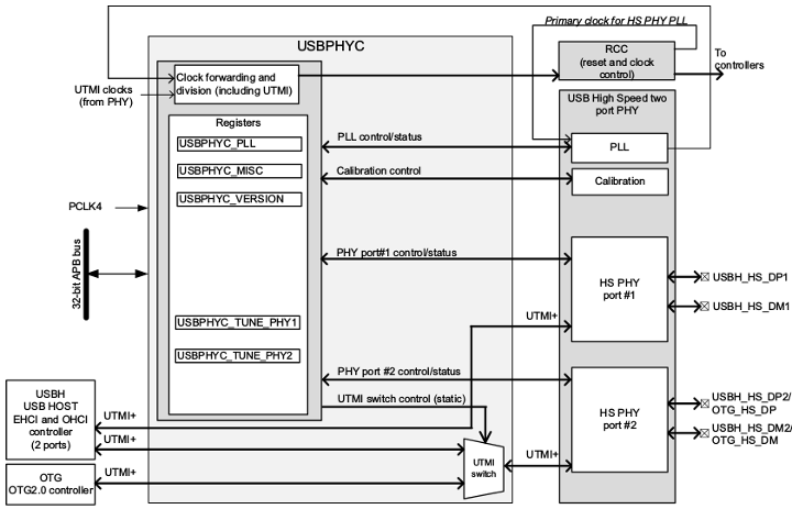
Refer to the STM32 MPU reference manuals for the complete list of features, and to the software frameworks and drivers, introduced below, to see which features are implemented.
153. Peripheral usage[edit | edit source]
This chapter is applicable in the scope of the OpenSTLinux BSP running on the Arm® Cortex®-A processor(s), and the FwST-M Package running on the Arm® Cortex®-M processor.
153.1. Boot time assignment[edit | edit source]
153.1.1. On STM32MP1 series[edit | edit source]
USBPHYC instances are boot devices that support Flash programming with STM32CubeProgrammer.
The USBPHYC peripheral is used by ROM code, FSBL and SSBL when using OTG in Device mode (DFU).
Click on ![]() to expand or collapse the legend...
to expand or collapse the legend...
| Domain | Peripheral | Boot time allocation | Comment | |||
|---|---|---|---|---|---|---|
| Instance | Cortex-A7 secure (ROM code) |
Cortex-A7 secure (TF-A BL2) |
Cortex-A7 nonsecure (U-Boot) | |||
| High speed interface | USBPHYC (USB HS PHY controller) | USBPHYC (USB HS PHY controller) | ✓ | ☐ | ☐ | The USBPHYC can be used by ROM code, FSBL and SSBL in DFU mode to support serial boot. It can be used also in U-boot by OTG and USBH with command line tools. |
153.2. Runtime assignment[edit | edit source]
153.2.1. On STM32MP13x lines [edit | edit source]
Click on ![]() to expand or collapse the legend...
to expand or collapse the legend...
| Domain | Peripheral | Runtime allocation | Comment | ||
|---|---|---|---|---|---|
| Instance | Cortex-A7 secure (OP-TEE) |
Cortex-A7 nonsecure (Linux) | |||
| High speed interface | USBPHYC (USB HS PHY controller) | USBPHYC (USB HS PHY controller) | ⬚ | ☐ | Assignment (single choice) |
153.2.2. On STM32MP15x lines [edit | edit source]
Click on ![]() to expand or collapse the legend...
to expand or collapse the legend...
| Domain | Peripheral | Runtime allocation | Comment | |||
|---|---|---|---|---|---|---|
| Instance | Cortex-A7 secure (OP-TEE) |
Cortex-A7 nonsecure (Linux) |
Cortex-M4 (STM32Cube) | |||
| High speed interface | USBPHYC (USB HS PHY controller) | USBPHYC (USB HS PHY controller) | ☐ | ⬚ | ||
154. Software frameworks and drivers[edit | edit source]
Below are listed the software frameworks and drivers managing the USBPHYC peripheral for the embedded software components listed in the above tables.
- Linux®: PHY framework
- U-Boot: PHY uclass (drivers/phy/phy-uclass.c ) and driver (drivers/phy/phy-stm32-usbphyc.c )
155. How to assign and configure the peripheral[edit | edit source]
The peripheral assignment can be done via the STM32CubeMX graphical tool (and manually completed if needed).
This tool also helps to configure the peripheral:
- partial device trees (pin control and clock tree) generation for the OpenSTLinux software components,
- HAL initialization code generation for the STM32CubeMPU Package.
The configuration is applied by the firmware running in the context in which the peripheral is assigned.
For U-boot and Linux kernel configuration, please refer to USBPHYC device tree configuration.
156. Article purpose[edit | edit source]
The purpose of this article is to:
- briefly introduce the I2C peripheral and its main features,
- indicate the peripheral instances assignment at boot time and their assignment at runtime (including whether instances can be allocated to secure contexts),
- list the software frameworks and drivers managing the peripheral,
- explain how to configure the peripheral.
157. Peripheral overview[edit | edit source]
The I2C bus interface serves as an interface between the microcontroller and the serial I2C bus.
It provides multi-master capability, and controls all I2C bus-specific sequencing, protocol, arbitration and timing.
The I2C controller allows to be a slave as well if need be.
It is also SMBus 2.0 compatible.
For more information about I2C please refer to this link: I2C wikipedia[1] or i2c-bus.org[2]
For more information about SMBus please refer to this link: SMBus wikipedia[3] or i2c-bus.org[4]
Here are the main features:
- Multi-master
- Standard (100 KHz) and fast speed modes (400 KHz and Plus 1 MHz)
- I2C 10-bit address
- I2C slave capabilities (programmable I2C address)
- DMA capabilities
- SMBus 2.0 compatible
- Standard bus protocol (quick command; byte, word, block read/write)
- Host notification
- Alert
Refer to the STM32 MPU reference manuals for the complete list of features, and to the software frameworks and drivers, introduced below, to see which features are implemented.
158. Peripheral usage[edit | edit source]
This chapter is applicable in the scope of the OpenSTLinux BSP running on the Arm® Cortex®-A processor(s), and the FwST-M Package running on the Arm® Cortex®-M processor.
158.1. Boot time assignment[edit | edit source]
158.1.1. On STM32MP1 series[edit | edit source]
The I2C peripheral is usually not used at boot time. But it may be used by the SSBL and/or FSBL (see Boot chain overview), for example, to configure a PMIC (see PMIC hardware components), or to access data stored in an external EEPROM.
Click on ![]() to expand or collapse the legend...
to expand or collapse the legend...
| Domain | Peripheral | Boot time allocation | Comment | |||
|---|---|---|---|---|---|---|
| Instance | Cortex-A7 secure (ROM code) |
Cortex-A7 secure (TF-A BL2) |
Cortex-A7 nonsecure (U-Boot) | |||
| Low speed interface | I2C | Any instance | ☐ | ☐ | ||
158.1.2. On STM32MP21x lines [edit | edit source]
158.1.2.1. For A35-TD flavor [edit | edit source]
Click on ![]() to expand or collapse the legend...
to expand or collapse the legend...
| Domain | Peripheral | Boot time allocation | Comment | |||
|---|---|---|---|---|---|---|
| Instance | Cortex-A35 secure (ROM code) |
Cortex-A35 secure (TF-A BL2) |
Cortex-A35 nonsecure (U-Boot) | |||
| Low speed interface | I2C | I2C1 | ☐ | ☐ | ||
| I2C2 | ☐ | ☐ | ||||
| I2C3 | ☐ | ☐ | ||||
158.1.2.2. For M33-TD flavor [edit | edit source]
Click on ![]() to expand or collapse the legend...
to expand or collapse the legend...
| Domain | Peripheral | Boot time allocation | Comment | ||||
|---|---|---|---|---|---|---|---|
| Instance | Cortex-A35 secure (ROM code) |
Cortex-A35 secure (TF-A BL2) |
Cortex-A35 nonsecure (U-Boot) |
Cortex-M33 secure (MCUboot) | |||
| Low speed interface | I2C | I2C1 | ☐ | ☐ | ☐ | ||
| I2C2 | ☐ | ☐ | ☐ | ||||
| I2C3 | ☐ | ☐ | ☐ | ||||
158.1.3. On STM32MP23x lines [edit | edit source]
158.1.3.1. For A35-TD flavor [edit | edit source]
Click on ![]() to expand or collapse the legend...
to expand or collapse the legend...
| Domain | Peripheral | Boot time allocation | Comment | |||
|---|---|---|---|---|---|---|
| Instance | Cortex-A35 secure (ROM code) |
Cortex-A35 secure (TF-A BL2) |
Cortex-A35 nonsecure (U-Boot) | |||
| Low speed interface | I2C | I2C1 | ☐ | ☐ | ||
| I2C2 | ☐ | ☐ | ||||
| I2C7 | ☐ | ☐ | ||||
| I2C8 | ☐ | ☐ | ||||
158.1.3.2. For M33-TD flavor [edit | edit source]
Click on ![]() to expand or collapse the legend...
to expand or collapse the legend...
| Domain | Peripheral | Boot time allocation | Comment | ||||
|---|---|---|---|---|---|---|---|
| Instance | Cortex-A35 secure (ROM code) |
Cortex-A35 secure (TF-A BL2) |
Cortex-A35 nonsecure (U-Boot) |
Cortex-M33 secure (MCUboot) | |||
| Low speed interface | I2C | I2C1 | ☐ | ☐ | ☐ | ||
| I2C2 | ☐ | ☐ | ☐ | ||||
| I2C7 | ☐ | ☐ | ☐ | ||||
| I2C8 | ☐ | ☐ | ☐ | ||||
158.1.4. On STM32MP25x lines [edit | edit source]
158.1.4.1. For A35-TD flavor [edit | edit source]
Click on ![]() to expand or collapse the legend...
to expand or collapse the legend...
| Domain | Peripheral | Boot time allocation | Comment | |||
|---|---|---|---|---|---|---|
| Instance | Cortex-A35 secure (ROM code) |
Cortex-A35 secure (TF-A BL2) |
Cortex-A35 nonsecure (U-Boot) | |||
| Low speed interface | I2C | I2C1 | ☐ | ☐ | ||
| I2C2 | ☐ | ☐ | ||||
| I2C3 | ☐ | ☐ | ||||
| I2C4 | ☐ | ☐ | ||||
| I2C5 | ☐ | ☐ | ||||
| I2C6 | ☐ | ☐ | ||||
| I2C7 | ☐ | ☐ | ||||
| I2C8 | ☐ | ☐ | ||||
158.1.4.2. For M33-TD flavor [edit | edit source]
Click on ![]() to expand or collapse the legend...
to expand or collapse the legend...
| Domain | Peripheral | Boot time allocation | Comment | ||||
|---|---|---|---|---|---|---|---|
| Instance | Cortex-A35 secure (ROM code) |
Cortex-A35 secure (TF-A BL2) |
Cortex-A35 nonsecure (U-Boot) |
Cortex-M33 secure (MCUboot) | |||
| Low speed interface | I2C | I2C1 | ☐ | ☐ | ☐ | ||
| I2C2 | ☐ | ☐ | ☐ | ||||
| I2C3 | ☐ | ☐ | ☐ | ||||
| I2C4 | ☐ | ☐ | ☐ | ||||
| I2C5 | ☐ | ☐ | ☐ | ||||
| I2C6 | ☐ | ☐ | ☐ | ||||
| I2C7 | ☐ | ☐ | ☐ | ||||
| I2C8 | ☐ | ☐ | ☐ | ||||
158.2. Runtime assignment[edit | edit source]
158.2.1. On STM32MP13x lines [edit | edit source]
Click on ![]() to expand or collapse the legend...
to expand or collapse the legend...
| Domain | Peripheral | Runtime allocation | Comment | ||
|---|---|---|---|---|---|
| Instance | Cortex-A7 secure (OP-TEE) |
Cortex-A7 nonsecure (Linux) | |||
| Low speed interface | I2C | I2C1 | ☐ | ||
| I2C2 | ☐ | ||||
| I2C3 | ☐ | ☐ | Assignment (single choice) | ||
| I2C4 | ☐ | ☐ | Assignment (single choice). Used for PMIC control on ST boards. | ||
| I2C5 | ☐ | ☐ | Assignment (single choice) | ||
158.2.2. On STM32MP15x lines [edit | edit source]
Click on ![]() to expand or collapse the legend...
to expand or collapse the legend...
| Domain | Peripheral | Runtime allocation | Comment | |||
|---|---|---|---|---|---|---|
| Instance | Cortex-A7 secure (OP-TEE) |
Cortex-A7 nonsecure (Linux) |
Cortex-M4 (STM32Cube) | |||
| Low speed interface | I2C | I2C1 | ☐ | ☐ | Assignment (single choice) | |
| I2C2 | ☐ | ☐ | Assignment (single choice) | |||
| I2C3 | ☐ | ☐ | Assignment (single choice) | |||
| I2C4 | ☐ | ☐ | Assignment (single choice). Used for PMIC control on ST boards. | |||
| I2C5 | ☐ | ☐ | Assignment (single choice) | |||
| I2C6 | ☐ | ☐ | Assignment (single choice) | |||
158.2.3. On STM32MP21x lines [edit | edit source]
The tables below are applicable to any TD flavor (A35-TD or M33-TD) ![]() .
.
Click on ![]() to expand or collapse the legend...
to expand or collapse the legend...
| Domain | Peripheral | Runtime allocation | Comment | ||||
|---|---|---|---|---|---|---|---|
| Instance | Cortex-A35 secure (OP-TEE / TF-A BL31) |
Cortex-A35 nonsecure (Linux) |
Cortex-M33 secure (TF-M) |
Cortex-M33 nonsecure (STM32Cube) | |||
| Low speed interface | I2C | I2C1 | ☐OP-TEE ⬚TF-A BL31 |
☐ | ☐ | ☐ | |
| I2C2 | ☐OP-TEE ⬚TF-A BL31 |
☐ | ☐ | ☐ | |||
| I2C3 | ☐OP-TEE ⬚TF-A BL31 |
☐ | ☐ | ☐ | Used for PMIC control on ST boards. | ||
158.2.4. On STM32MP23x lines [edit | edit source]
The tables below are applicable to any TD flavor (A35-TD or M33-TD) ![]() .
.
Click on ![]() to expand or collapse the legend...
to expand or collapse the legend...
| Domain | Peripheral | Runtime allocation | Comment | ||||
|---|---|---|---|---|---|---|---|
| Instance | Cortex-A35 secure (OP-TEE / TF-A BL31) |
Cortex-A35 nonsecure (Linux) |
Cortex-M33 secure (TF-M) |
Cortex-M33 nonsecure (STM32Cube) | |||
| Low speed interface | I2C | I2C1 | ☐OP-TEE ⬚TF-A BL31 |
☐ | ☐ | ☐ | |
| I2C2 | ☐OP-TEE ⬚TF-A BL31 |
☐ | ☐ | ☐ | |||
| I2C7 | ☐OP-TEE ⬚TF-A BL31 |
☐ | ☐ | ☐ | Used for PMIC control on ST boards. | ||
| I2C8 | ☐OP-TEE ⬚TF-A BL31 |
☐ | ☐ | ☐ | |||
158.2.5. On STM32MP25x lines [edit | edit source]
The tables below are applicable to any TD flavor (A35-TD or M33-TD) ![]() .
.
Click on ![]() to expand or collapse the legend...
to expand or collapse the legend...
| Domain | Peripheral | Runtime allocation | Comment | |||||
|---|---|---|---|---|---|---|---|---|
| Instance | Cortex-A35 secure (OP-TEE / TF-A BL31) |
Cortex-A35 nonsecure (Linux) |
Cortex-M33 secure (TF-M) |
Cortex-M33 nonsecure (STM32Cube) |
Cortex-M0+ (STM32Cube) | |||
| Low speed interface | I2C | I2C1 | ☐OP-TEE ⬚TF-A BL31 |
☐ | ☐ | ☐ | ||
| I2C2 | ☐OP-TEE ⬚TF-A BL31 |
☐ | ☐ | ☐ | ||||
| I2C3 | ☐OP-TEE ⬚TF-A BL31 |
☐ | ☐ | ☐ | ||||
| I2C4 | ☐OP-TEE ⬚TF-A BL31 |
☐ | ☐ | ☐ | ||||
| I2C5 | ☐OP-TEE ⬚TF-A BL31 |
☐ | ☐ | ☐ | ||||
| I2C6 | ☐OP-TEE ⬚TF-A BL31 |
☐ | ☐ | ☐ | ||||
| I2C7 | ☐OP-TEE ⬚TF-A BL31 |
☐ | ☐ | ☐ | Used for PMIC control on ST boards. | |||
| I2C8 | ☐OP-TEE ⬚TF-A BL31 |
☐ | ☐ | ☐ | ☐ | |||
159. Software frameworks and drivers[edit | edit source]
Below are listed the software frameworks and drivers managing the I2C peripheral for the embedded software components listed in the above tables.
- Linux®: I2C framework
- OP-TEE: I2C driver and header file of I2C OP-TEE driver
- TF-M: I2C driver and header file of I2C TF-M driver
- STM32Cube: I2C HAL driver and header file of I2C HAL module
- TF-A BL2: I2C driver
- U-Boot: I2C driver
160. How to assign and configure the peripheral[edit | edit source]
The peripheral assignment can be done via the STM32CubeMX graphical tool (and manually completed if needed).
This tool also helps to configure the peripheral:
- partial device trees (pin control and clock tree) generation for the OpenSTLinux software components,
- HAL initialization code generation for the STM32CubeMPU Package.
The configuration is applied by the firmware running in the context in which the peripheral is assigned.
For Linux® kernel configuration, please refer to I2C configuration.
Please refer to I2C device tree configuration for detailed information on how to configure I2C peripherals.
161. References[edit | edit source]
162. Article purpose[edit | edit source]
The purpose of this article is to:
- briefly introduce the SPI peripheral and its main features,
- indicate the peripheral instances assignment at boot time and their assignment at runtime (including whether instances can be allocated to secure contexts),
- list the software frameworks and drivers managing the peripheral,
- explain how to configure the peripheral.
163. Peripheral overview[edit | edit source]
The SPI peripheral is used to communicate with an external devices using the SPI (Serial Peripheral Interface).
A subset of the SPI instances supports the I2S audio protocol. These SPI/I2S peripherals can alternatively be used in audio applications, when they are configured as an I2S interface. Refer to peripheral usage chapter to check I2S feature support for each SPI instance.
163.1. SPI main features[edit | edit source]
- Full-duplex, half-duplex and simplex synchronous modes.
- Slave and master modes.
163.2. I2S main features[edit | edit source]
Only available for SPI supporting I2S mode.
- Full-duplex or simplex modes.
- Slave and master modes.
- Four audio protocols supported.
163.3. Specific features[edit | edit source]
Some of the SPI peripheral characteristics depend on I2S support, as summarized in following table:
| SPI modes/features | I2S supported | I2S not supported |
|---|---|---|
| Rx & TxFIFO size (N) [x 8-bit] | 16 | 8 |
| Maximum configurable data size [bits] | 32 | 16 |
On STM32MP25x lines ![]() , spi8 has only a limited feature set compared to other 7 instances, with only 8 / 16 bits data size and shorter transfer size compared to other instances.
, spi8 has only a limited feature set compared to other 7 instances, with only 8 / 16 bits data size and shorter transfer size compared to other instances.
Refer to the STM32 MPU reference manuals for the complete list of features, and to the software frameworks and drivers, introduced below, to see which features are implemented.
164. Peripheral usage[edit | edit source]
This chapter is applicable in the scope of the OpenSTLinux BSP running on the Arm® Cortex®-A processor(s), and the FwST-M Package running on the Arm® Cortex®-M processor.
164.1. Boot time assignment[edit | edit source]
164.1.1. On STM32MP1 series[edit | edit source]
The SPI peripheral is not used at boot time.
164.1.2. On STM32MP2 series[edit | edit source]
164.1.2.1. For A35-TD flavor [edit | edit source]
Click on ![]() to expand or collapse the legend...
to expand or collapse the legend...
| Domain | Peripheral | Boot time allocation | Comment | |||
|---|---|---|---|---|---|---|
| Instance | Cortex-A35 secure (ROM code) |
Cortex-A35 secure (TF-A BL2) |
Cortex-A35 nonsecure (U-Boot) | |||
| Low speed interface or audio | SPI | SPI1 | ⬚ | ☐ | ||
| SPI2 | ⬚ | ☐ | ||||
| SPI3 | ⬚ | ☐ | ||||
| SPI4 | ⬚ | ☐ | ||||
| SPI5 | ⬚ | ☐ | ||||
| SPI6 | ⬚ | ☐ | ||||
164.1.2.2. For M33-TD flavor [edit | edit source]
Click on ![]() to expand or collapse the legend...
to expand or collapse the legend...
| Domain | Peripheral | Boot time allocation | Comment | ||||
|---|---|---|---|---|---|---|---|
| Instance | Cortex-A35 secure (ROM code) |
Cortex-A35 secure (TF-A BL2) |
Cortex-A35 nonsecure (U-Boot) |
Cortex-M33 secure (MCUboot) | |||
| Low speed interface or audio | SPI | SPI1 | ⬚ | ☐ | ⬚ | ||
| SPI2 | ⬚ | ☐ | ⬚ | ||||
| SPI3 | ⬚ | ☐ | ⬚ | ||||
| SPI4 | ⬚ | ☐ | ⬚ | ||||
| SPI5 | ⬚ | ☐ | ⬚ | ||||
| SPI6 | ⬚ | ☐ | ⬚ | ||||
164.2. Runtime assignment[edit | edit source]
164.2.1. On STM32MP13x lines [edit | edit source]
Click on ![]() to expand or collapse the legend...
to expand or collapse the legend...
| Domain | Peripheral | Runtime allocation | Comment | ||
|---|---|---|---|---|---|
| Instance | Cortex-A7 secure (OP-TEE) |
Cortex-A7 nonsecure (Linux) | |||
| Low speed interface or audio |
SPI | SPI2S1 | ☐ | ||
| SPI2S2 | ☐ | ||||
| SPI2S3 | ☐ | ||||
| SPI2S4 | ⬚ | ☐ | Assignment (single choice) | ||
| SPI5 | ⬚ | ☐ | Assignment (single choice) | ||
164.2.2. On STM32MP15x lines [edit | edit source]
Click on ![]() to expand or collapse the legend...
to expand or collapse the legend...
| Domain | Peripheral | Runtime allocation | Comment | |||
|---|---|---|---|---|---|---|
| Instance | Cortex-A7 secure (OP-TEE) |
Cortex-A7 nonsecure (Linux) |
Cortex-M4 (STM32Cube) | |||
| Low speed interface or audio |
SPI | SPI2S1 | ☐ | ☐ | Assignment (single choice) | |
| SPI2S2 | ☐ | ☐ | Assignment (single choice) | |||
| SPI2S3 | ☐ | ☐ | Assignment (single choice) | |||
| SPI4 | ☐ | ☐ | Assignment (single choice) | |||
| SPI5 | ☐ | ☐ | Assignment (single choice) | |||
| SPI6 | ⬚ | ☐ | Assignment (single choice) | |||
164.2.3. On STM32MP21x lines [edit | edit source]
The tables below are applicable to any TD flavor (A35-TD or M33-TD) ![]() .
.
Click on ![]() to expand or collapse the legend...
to expand or collapse the legend...
| Domain | Peripheral | Runtime allocation | Comment | ||||
|---|---|---|---|---|---|---|---|
| Instance | Cortex-A35 secure (OP-TEE / TF-A BL31) |
Cortex-A35 nonsecure (Linux) |
Cortex-M33 secure (TF-M) |
Cortex-M33 nonsecure (STM32Cube) | |||
| Low speed interface or audio | SPI | SPI1 | ⬚OP-TEE | ☐ | ⬚ | ☐ | |
| SPI2 | ⬚OP-TEE | ☐ | ⬚ | ☐ | |||
| SPI3 | ⬚OP-TEE | ☐ | ⬚ | ☐ | |||
| SPI4 | ⬚OP-TEE | ☐ | ⬚ | ☐ | |||
| SPI5 | ⬚OP-TEE | ☐ | ⬚ | ☐ | |||
| SPI6 | ⬚OP-TEE | ☐ | ⬚ | ☐ | |||
164.2.4. On STM32MP23x lines [edit | edit source]
The tables below are applicable to any TD flavor (A35-TD or M33-TD) ![]() .
.
Click on ![]() to expand or collapse the legend...
to expand or collapse the legend...
| Domain | Peripheral | Runtime allocation | Comment | ||||
|---|---|---|---|---|---|---|---|
| Instance | Cortex-A35 secure (OP-TEE / TF-A BL31) |
Cortex-A35 nonsecure (Linux) |
Cortex-M33 secure (TF-M) |
Cortex-M33 nonsecure (STM32Cube) | |||
| Low speed interface or audio | SPI | SPI1 | ⬚OP-TEE | ☐ | ⬚ | ☐ | |
| SPI2 | ⬚OP-TEE | ☐ | ⬚ | ☐ | |||
| SPI3 | ⬚OP-TEE | ☐ | ⬚ | ☐ | |||
| SPI4 | ⬚OP-TEE | ☐ | ⬚ | ☐ | |||
| SPI5 | ⬚OP-TEE | ☐ | ⬚ | ☐ | |||
| SPI8 | ⬚OP-TEE | ☐ | ⬚ | ☐ | |||
164.2.5. On STM32MP25x lines [edit | edit source]
The tables below are applicable to any TD flavor (A35-TD or M33-TD) ![]() .
.
Click on ![]() to expand or collapse the legend...
to expand or collapse the legend...
| Domain | Peripheral | Runtime allocation | Comment | |||||
|---|---|---|---|---|---|---|---|---|
| Instance | Cortex-A35 secure (OP-TEE / TF-A BL31) |
Cortex-A35 nonsecure (Linux) |
Cortex-M33 secure (TF-M) |
Cortex-M33 nonsecure (STM32Cube) |
Cortex-M0+ (STM32Cube) | |||
| Low speed interface or audio | SPI | SPI1 | ⬚OP-TEE | ☐ | ⬚ | ☐ | ||
| SPI2 | ⬚OP-TEE | ☐ | ⬚ | ☐ | ||||
| SPI3 | ⬚OP-TEE | ☐ | ⬚ | ☐ | ||||
| SPI4 | ⬚OP-TEE | ☐ | ⬚ | ☐ | ||||
| SPI5 | ⬚OP-TEE | ☐ | ⬚ | ☐ | ||||
| SPI6 | ⬚OP-TEE | ☐ | ⬚ | ☐ | ||||
| SPI7 | ⬚OP-TEE | ☐ | ⬚ | ☐ | ||||
| SPI8 | ⬚OP-TEE | ☐ | ⬚ | ☐ | ☐ | |||
165. Software frameworks and drivers[edit | edit source]
Below are listed the software frameworks and drivers managing the SPI peripheral for the embedded software components listed in the above tables.
- Linux®: Linux SPI framework for SPI configured in SPI mode, and Linux ALSA framework for SPI configured in I2S mode (only for SPI supporting I2S feature)
- STM32Cube: HAL SPI driver for SPI configured in SPI mode. HAL I2S driver is not available for SPI configured in I2S mode.
166. How to assign and configure the peripheral[edit | edit source]
The peripheral assignment can be done via the STM32CubeMX graphical tool (and manually completed if needed).
This tool also helps to configure the peripheral:
- partial device trees (pin control and clock tree) generation for the OpenSTLinux software components,
- HAL initialization code generation for the STM32CubeMPU Package.
The configuration is applied by the firmware running in the context in which the peripheral is assigned.
When the Arm® Cortex®-A7 core operates in non-secure access mode, the SPI is controlled by the Linux kernel framework.
- SPI mode:
Refer to SPI framework to check how to drive SPI through Linux kernel.
- I2S mode:
Refer to I2S Linux driver to drive the SPI through Linux kernel ALSA framework. Refer to Soundcard configuration to configure it through the Linux kernel device tree[1].
167. References[edit | edit source]
168. Article purpose[edit | edit source]
The purpose of this article is to:
- briefly introduce the USART peripheral and its main features,
- indicate the peripheral instances assignment at boot time and their assignment at runtime (including whether instances can be allocated to secure contexts),
- list the software frameworks and drivers managing the peripheral,
- explain how to configure the peripheral.
169. Peripheral overview[edit | edit source]
The USART peripheral is used to interconnect STM32 MPU devices with other systems, typically via RS232 or RS485 protocols. In addition, the USART can be used for smartcard interfacing or SPI master/slave operation and supports the Synchronous mode.
The UART peripheral is similar to the USART, but does not support the Synchronous mode nor the smartcard interfacing.
High-speed data communications can be achieved by using the DMA or MDMA on STM32MP1 series and HPDMA on STM32MP2 series for multibuffer configuration.
Refer to the STM32 MPU reference manuals for the complete list of features, and to the software frameworks and drivers, introduced below, to see which features are implemented.
170. Peripheral usage[edit | edit source]
This chapter is applicable in the scope of the OpenSTLinux BSP running on the Arm® Cortex®-A processor(s), and the FwST-M Package running on the Arm® Cortex®-M processor.
170.1. Boot time assignment[edit | edit source]
170.1.1. On STM32MP1 series[edit | edit source]
All USART and UART instances that are not securable via ETZPC are boot devices that support serial boot for Flash programming with STM32CubeProgrammer.
Click on ![]() to expand or collapse the legend...
to expand or collapse the legend...
| Domain | Peripheral | Boot time allocation | Comment | |||
|---|---|---|---|---|---|---|
| Instance | Cortex-A7 secure (ROM code) |
Cortex-A7 secure (TF-A BL2) |
Cortex-A7 nonsecure (U-Boot) | |||
| Low speed interface | USART | USART1 | ☐ | ☐ | ||
| USART2 | ☐ | ☐ | ☐ | |||
| USART3 | ☐ | ☐ | ☐ | |||
| UART4 | ☐ | ☐ | ☐ | |||
| UART5 | ☐ | ☐ | ☐ | |||
| USART6 | ☐ | ☐ | ☐ | |||
| UART7 | ☐ | ☐ | ☐ | |||
| UART8 | ☐ | ☐ | ☐ | |||
170.1.2. On STM32MP21x lines [edit | edit source]
170.1.2.1. For A35-TD flavor [edit | edit source]
Some USART/UART instances are boot devices that support serial boot for Flash programming with STM32CubeProgrammer.
Click on ![]() to expand or collapse the legend...
to expand or collapse the legend...
| Domain | Peripheral | Boot time allocation | Comment | |||
|---|---|---|---|---|---|---|
| Instance | Cortex-A35 secure (ROM code) |
Cortex-A35 secure (TF-A BL2) |
Cortex-A35 nonsecure (U-Boot) | |||
| Low speed interface | USART | UART4 | ☐ | ☐ | ☐ | |
| UART5 | ☐ | ☐ | ☐ | |||
| UART7 | ☐ | ☐ | ||||
| UART1 | ☐ | ☐ | ||||
| USART2 | ☐ | ☐ | ☐ | |||
| USART3 | ☐ | ☐ | ☐ | |||
| USART6 | ☐ | ☐ | ☐ | |||
170.1.2.2. For M33-TD flavor [edit | edit source]
Some USART/UART instances are boot devices that support serial boot for Flash programming with STM32CubeProgrammer.
Click on ![]() to expand or collapse the legend...
to expand or collapse the legend...
| Domain | Peripheral | Boot time allocation | Comment | ||||
|---|---|---|---|---|---|---|---|
| Instance | Cortex-A35 secure (ROM code) |
Cortex-A35 secure (TF-A BL2) |
Cortex-A35 nonsecure (U-Boot) |
Cortex-M33 secure (MCUboot) | |||
| Low speed interface | USART | UART4 | ☐ | ☐ | ☐ | ☐ | |
| UART5 | ☐ | ☐ | ☐ | ☐ | |||
| UART7 | ☐ | ☐ | ☐ | ||||
| USART1 | ☐ | ☐ | ☐ | ||||
| USART2 | ☐ | ☐ | ☐ | ☐ | |||
| USART3 | ☐ | ☐ | ☐ | ☐ | |||
| USART6 | ☐ | ☐ | ☐ | ☐ | |||
170.1.3. On STM32MP23x lines [edit | edit source]
170.1.3.1. For A35-TD flavor [edit | edit source]
Some USART/UART instances are boot devices that support serial boot for Flash programming with STM32CubeProgrammer.
Click on ![]() to expand or collapse the legend...
to expand or collapse the legend...
| Domain | Peripheral | Boot time allocation | Comment | |||
|---|---|---|---|---|---|---|
| Instance | Cortex-A35 secure (ROM code) |
Cortex-A35 secure (TF-A BL2) |
Cortex-A35 nonsecure (U-Boot) | |||
| Low speed interface | USART | UART4 | ☐ | ☐ | ||
| UART5 | ☐ | ☐ | ☐ | |||
| UART7 | ☐ | ☐ | ||||
| USART1 | ☐ | ☐ | ||||
| USART2 | ☐ | ☐ | ☐ | |||
| USART3 | ☐ | ☐ | ||||
| USART6 | ☐ | ☐ | ☐ | |||
170.1.3.2. For M33-TD flavor [edit | edit source]
Some USART/UART instances are boot devices that support serial boot for Flash programming with STM32CubeProgrammer.
Click on ![]() to expand or collapse the legend...
to expand or collapse the legend...
| Domain | Peripheral | Boot time allocation | Comment | ||||
|---|---|---|---|---|---|---|---|
| Instance | Cortex-A35 secure (ROM code) |
Cortex-A35 secure (TF-A BL2) |
Cortex-A35 nonsecure (U-Boot) |
Cortex-M33 secure (MCUboot) | |||
| Low speed interface | USART | UART4 | ☐ | ☐ | ☐ | ||
| UART5 | ☐ | ☐ | ☐ | ☐ | |||
| UART7 | ☐ | ☐ | ☐ | ||||
| USART1 | ☐ | ☐ | ☐ | ||||
| USART2 | ☐ | ☐ | ☐ | ☐ | |||
| USART3 | ☐ | ☐ | ☐ | ||||
| USART6 | ☐ | ☐ | ☐ | ☐ | |||
170.1.4. On STM32MP25x lines [edit | edit source]
170.1.4.1. For A35-TD flavor [edit | edit source]
Some USART/UART instances are boot devices that support serial boot for Flash programming with STM32CubeProgrammer.
Click on ![]() to expand or collapse the legend...
to expand or collapse the legend...
| Domain | Peripheral | Boot time allocation | Comment | |||
|---|---|---|---|---|---|---|
| Instance | Cortex-A35 secure (ROM code) |
Cortex-A35 secure (TF-A BL2) |
Cortex-A35 nonsecure (U-Boot) | |||
| Low speed interface | USART | UART4 | ☐ | ☐ | ||
| UART5 | ☐ | ☐ | ☐ | |||
| UART7 | ☐ | ☐ | ||||
| UART8 | ☐ | ☐ | ☐ | |||
| UART9 | ☐ | ☐ | ☐ | |||
| USART1 | ☐ | ☐ | ||||
| USART2 | ☐ | ☐ | ☐ | |||
| USART3 | ☐ | ☐ | ||||
| USART6 | ☐ | ☐ | ☐ | |||
170.1.4.2. For M33-TD flavor [edit | edit source]
Some USART/UART instances are boot devices that support serial boot for Flash programming with STM32CubeProgrammer.
Click on ![]() to expand or collapse the legend...
to expand or collapse the legend...
| Domain | Peripheral | Boot time allocation | Comment | ||||
|---|---|---|---|---|---|---|---|
| Instance | Cortex-A35 secure (ROM code) |
Cortex-A35 secure (TF-A BL2) |
Cortex-A35 nonsecure (U-Boot) |
Cortex-M33 secure (MCUboot) | |||
| Low speed interface | USART | UART4 | ☐ | ☐ | ☐ | ||
| UART5 | ☐ | ☐ | ☐ | ☐ | |||
| UART7 | ☐ | ☐ | ☐ | ||||
| UART8 | ☐ | ☐ | ☐ | ☐ | |||
| UART9 | ☐ | ☐ | ☐ | ☐ | |||
| USART1 | ☐ | ☐ | ☐ | ||||
| USART2 | ☐ | ☐ | ☐ | ☐ | |||
| USART3 | ☐ | ☐ | ☐ | ||||
| USART6 | ☐ | ☐ | ☐ | ☐ | |||
170.2. Runtime assignment[edit | edit source]
170.2.1. On STM32MP13x lines [edit | edit source]
Click on ![]() to expand or collapse the legend...
to expand or collapse the legend...
| Domain | Peripheral | Runtime allocation | Comment | ||
|---|---|---|---|---|---|
| Instance | Cortex-A7 secure (OP-TEE) |
Cortex-A7 nonsecure (Linux) | |||
| Low speed interface | USART | USART1 | ☐ | ☐ | |
| USART2 | ☐ | ☐ | |||
| USART3 | ☐ | ||||
| UART4 | ☐ | ||||
| UART5 | ☐ | ||||
| USART6 | ☐ | ||||
| UART7 | ☐ | ||||
| UART8 | ☐ | ||||
170.2.2. On STM32MP15x lines [edit | edit source]
Click on ![]() to expand or collapse the legend...
to expand or collapse the legend...
| Domain | Peripheral | Runtime allocation | Comment | |||
|---|---|---|---|---|---|---|
| Instance | Cortex-A7 secure (OP-TEE) |
Cortex-A7 nonsecure (Linux) |
Cortex-M4 (STM32Cube) | |||
| Low speed interface | USART | USART1 | ☐ | ☐ | ||
| USART2 | ☐ | ☐ | ||||
| USART3 | ☐ | ☐ | ||||
| UART4 | ☐ | ☐ | ||||
| UART5 | ☐ | ☐ | ||||
| USART6 | ☐ | ☐ | ||||
| UART7 | ☐ | ☐ | ||||
| UART8 | ☐ | ☐ | ||||
170.2.3. On STM32MP21x lines [edit | edit source]
Click on ![]() to expand or collapse the legend...
to expand or collapse the legend...
| Domain | Peripheral | Runtime allocation | Comment | ||||
|---|---|---|---|---|---|---|---|
| Instance | Cortex-A35 secure (OP-TEE / TF-A BL31) |
Cortex-A35 nonsecure (Linux) |
Cortex-M33 secure (TF-M) |
Cortex-M33 nonsecure (STM32Cube) | |||
| Low speed interface | USART | UART4 | ☐OP-TEE ☐TF-A BL31 |
☐ | ☐ | ☐ | |
| UART5 | ☐OP-TEE ☐TF-A BL31 |
☐ | ☐ | ☐ | |||
| UART7 | ☐OP-TEE ☐TF-A BL31 |
☐ | ☐ | ☐ | |||
| USART1 | ☐OP-TEE ☐TF-A BL31 |
☐ | ☐ | ☐ | |||
| USART2 | ☐OP-TEE ☐TF-A BL31 |
☐ | ☐ | ☐ | |||
| USART3 | ☐OP-TEE ☐TF-A BL31 |
☐ | ☐ | ☐ | |||
| USART6 | ☐OP-TEE ☐TF-A BL31 |
☐ | ☐ | ☐ | |||
170.2.4. On STM32MP23x lines [edit | edit source]
The tables below are applicable to any TD flavor (A35-TD or M33-TD) ![]() .
.
Click on ![]() to expand or collapse the legend...
to expand or collapse the legend...
| Domain | Peripheral | Runtime allocation | Comment | ||||
|---|---|---|---|---|---|---|---|
| Instance | Cortex-A35 secure (OP-TEE / TF-A BL31) |
Cortex-A35 nonsecure (Linux) |
Cortex-M33 secure (TF-M) |
Cortex-M33 nonsecure (STM32Cube) | |||
| Low speed interface | USART | UART4 | ☐OP-TEE ☐TF-A BL31 |
☐ | ☐ | ☐ | |
| UART5 | ☐OP-TEE ☐TF-A BL31 |
☐ | ☐ | ☐ | |||
| UART7 | ☐OP-TEE ☐TF-A BL31 |
☐ | ☐ | ☐ | |||
| USART1 | ☐OP-TEE ☐TF-A BL31 |
☐ | ☐ | ☐ | |||
| USART2 | ☐OP-TEE ☐TF-A BL31 |
☐ | ☐ | ☐ | |||
| USART3 | ☐OP-TEE ☐TF-A BL31 |
☐ | ☐ | ☐ | |||
| USART6 | ☐OP-TEE ☐TF-A BL31 |
☐ | ☐ | ☐ | |||
170.2.5. On STM32MP25x lines [edit | edit source]
The tables below are applicable to any TD flavor (A35-TD or M33-TD) ![]() .
.
Click on ![]() to expand or collapse the legend...
to expand or collapse the legend...
| Domain | Peripheral | Runtime allocation | Comment | |||||
|---|---|---|---|---|---|---|---|---|
| Instance | Cortex-A35 secure (OP-TEE / TF-A BL31) |
Cortex-A35 nonsecure (Linux) |
Cortex-M33 secure (TF-M) |
Cortex-M33 nonsecure (STM32Cube) |
Cortex-M0+ (STM32Cube) | |||
| Low speed interface | USART | UART4 | ☐OP-TEE ☐TF-A BL31 |
☐ | ☐ | ☐ | ||
| UART5 | ☐OP-TEE ☐TF-A BL31 |
☐ | ☐ | ☐ | ||||
| UART7 | ☐OP-TEE ☐TF-A BL31 |
☐ | ☐ | ☐ | ||||
| UART8 | ☐OP-TEE ☐TF-A BL31 |
☐ | ☐ | ☐ | ||||
| UART9 | ☐OP-TEE ☐TF-A BL31 |
☐ | ☐ | ☐ | ||||
| USART1 | ☐OP-TEE ☐TF-A BL31 |
☐ | ☐ | ☐ | ||||
| USART2 | ☐OP-TEE ☐TF-A BL31 |
☐ | ☐ | ☐ | ||||
| USART3 | ☐OP-TEE ☐TF-A BL31 |
☐ | ☐ | ☐ | ||||
| USART6 | ☐OP-TEE ☐TF-A BL31 |
☐ | ☐ | ☐ | ||||
171. Software frameworks and drivers[edit | edit source]
The STM32 MPU devices feature USART instances (supporting both Asynchronous and Synchronous modes), and UART instances (supporting only Asynchronous mode).
Below are listed the software frameworks and drivers managing the USART peripheral for the embedded software components listed in the above tables.
- Linux®: serial/tty framework; however, the Linux® kernel supports only the UART Asynchronous mode (Synchronous mode not supported)
- OP-TEE: USART driver and header file of USART OP-TEE driver , typically to communicate with a smartcard
- STM32Cube: USART HAL driver and header file of USART HAL module ; both USART synchronous and asynchronous modes are supported by the STM32Cube MPU Package
172. How to assign and configure the peripheral[edit | edit source]
The peripheral assignment can be done via the STM32CubeMX graphical tool (and manually completed if needed).
This tool also helps to configure the peripheral:
- partial device trees (pin control and clock tree) generation for the OpenSTLinux software components,
- HAL initialization code generation for the STM32CubeMPU Package.
The configuration is applied by the firmware running in the context in which the peripheral is assigned.
See also additional information in the Serial TTY device tree configuration article for Linux®.
173. How to go further[edit | edit source]
Additional documentation on USART peripheral is available on st.com:
- STM32 USART training [1] presents the STM32 Universal Synchronous/Asynchronous Receiver/Transmitter interface.
- STM32 USART automatic baud rate detection [2] presents STM32 USART automatic baud rate detection.
174. References[edit | edit source]
FMC internal peripheral
QUADSPI internal peripheral
SDMMC internal peripheral
ETH internal peripheral
FDCAN internal peripheral
DTS internal peripheral
PWR internal peripheral
RCC internal peripheral
BSEC internal peripheral
CRC internal peripheral
CRYP internal peripheral
ETZPC internal peripheral
HASH internal peripheral
RNG internal peripheral
TZC internal peripheral
TAMP internal peripheral
DBGMCU internal peripheral
HDP internal peripheral
STM internal peripheral
CEC internal peripheral
DCMI internal peripheral
DSI internal peripheral
GPU internal peripheral
LTDC internal peripheral
|}
175. References[edit | edit source]
Arm® is a registered trademark of Arm Limited (or its subsidiaries) in the US and/or elsewhere. ![]()
Arm® is a registered trademark of Arm Limited (or its subsidiaries) in the US and/or elsewhere. ![]()