Registered User mNo edit summary |
Registered User mNo edit summary |
||
| (57 intermediate revisions by 6 users not shown) | |||
| Line 1: | Line 1: | ||
<noinclude>{{ApplicableFor | |||
|MPUs list=STM32MP13x, STM32MP15x | |||
|MPUs checklist=STM32MP13x, STM32MP15x | |||
}}</noinclude> | |||
__FORCETOC__ | |||
== Article purpose == | |||
This article explains the {{MicroprocessorDevice | device=1}} DMA topology and the associated configurations recommended by ST. | |||
== DMA specificities per STM32 MPU devices== | |||
==={{MicroprocessorDevice | device=13}}=== | |||
The STM32MP13xx MPUs feature four DMA instances: | |||
* 1 [[MDMA internal peripheral]] dedicated to the transfers between some internal peripherals and the external memories (DDR), and between the internal and external memories. | |||
* '''3''' [[DMA internal peripheral]] (DMA1/DMA2/DMA3) dedicated to the transfers between internal peripherals and the internal SRAM. The DMA1 and DMA2 instances are coupled with DMAMUX1. DMA3 is coupled with DMAMUX2: [[DMAMUX internal peripheral]] is in charge of routing the internal peripheral requests to the DMA channels. | |||
{{Info| Transfers between internal peripherals and DDR, via DMA1/DMA2/DMA3, are possible but not recommended for high-bandwidth or latency-critical transfers.}} | |||
==={{MicroprocessorDevice | device=15}}=== | |||
The STM32MP15xx MPUs feature three DMA instances: | |||
* 1 [[MDMA internal peripheral]] dedicated to the transfers between some internal peripherals and the external memories (DDR), and between the internal and external memories. | |||
* '''2''' [[DMA internal peripheral]] (DMA1/DMA2) dedicated to the transfers between internal peripherals and the internal SRAM. These two DMA instances are coupled with a [[DMAMUX internal peripheral]] in charge of routing the internal peripheral requests to the DMA channels. | |||
{{Info| Transfers between internal peripherals and DDR, via DMA1/DMA2, are possible but not recommended for high-bandwidth or latency-critical transfers.}} | |||
==DMA configurations== | |||
The following figures show the different DMA configurations available on STM32MP1 and the associated requests and data connections. | |||
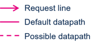
The legend below illustrates the request lines and datapath. | |||
[[File:DMA_legend.png|link=|center|200px]] | |||
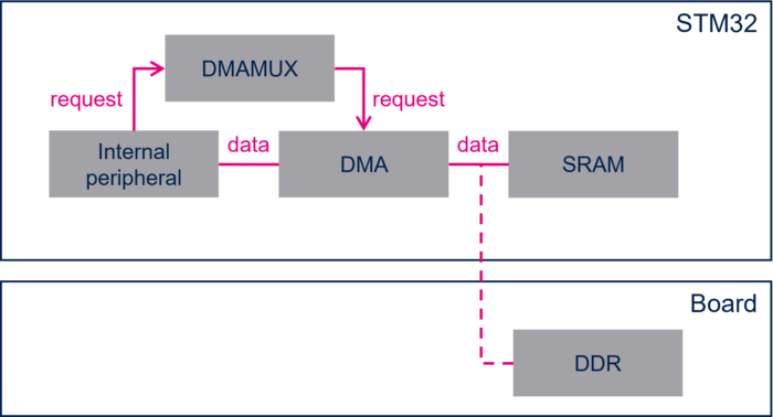
* Internal peripherals - internal SRAM with [[DMA internal peripheral|DMA]] transfer | |||
[[File:DMA_transfer.png|700px|link=|center]] | |||
:In this configuration, the dataflow is: | |||
::* peripheral to memory direction: data are directly transferred from the peripheral to the final internal RAM buffer by [[DMA internal peripheral|DMA]]. | |||
::* memory to peripheral direction: data are transferred from the original internal SRAM buffer to the peripheral by [[DMA internal peripheral|DMA]]. | |||
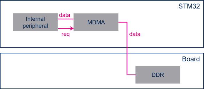
* Internal peripherals - DDR with [[MDMA internal peripheral|MDMA]] transfer | |||
[[File:MDMA_transfer.png|700px|link=|center]] | |||
:In this configuration, the dataflow is: | |||
::* peripheral to memory direction: data are directly transferred from the peripheral to the final DDR buffer by [[MDMA internal peripheral|MDMA]]. | |||
::* memory to peripheral direction: data are transferred from the original DDR buffer to the peripheral by [[MDMA internal peripheral|MDMA]]. | |||
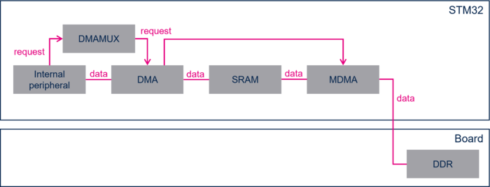
* Internal peripherals - DDR with [[DMA internal peripheral|DMA]] - [[MDMA internal peripheral|MDMA]] chained transfer | |||
[[File:DMA_MDMA_transfer.png|700px|link=|center]] | |||
:In this configuration, the dataflow is: | |||
::* peripheral to memory direction: data are transferred from the peripheral to the temporary internal SRAM buffer by [[DMA internal peripheral|DMA]], then from the temporary internal SRAM buffer to the DDR buffer by [[MDMA internal peripheral|MDMA]]. | |||
::* memory to peripheral direction: data are transferred from the DDR buffer to the temporary internal SRAM buffer by [[MDMA internal peripheral|MDMA]], then from the temporary internal SRAM buffer to the peripheral by [[DMA internal peripheral|DMA]]. | |||
For more information about the DMA controllers above, and to know the DMA configuration that must be used with each internal peripheral, refer to [[STM32 MPU resources#Reference manuals| reference manuals corresponding to the used STM32 MPU ]]. | |||
== STMicroelectronics recommendations== | |||
=== For Arm<sup>®</sup> Cortex<sup>®</sup>-M4 execution context=== | |||
The Arm<sup>®</sup> Cortex<sup>®</sup>-M4 accesses by default the internal SRAM for code and data.<br/> | |||
In this context, the DMA transfers operate only between the peripheral and the internal SRAM.<br/> | |||
This is why ST recommends to dedicate one [[DMA internal peripheral]] to Arm<sup>®</sup> Cortex<sup>®</sup>-M4.<br/> | |||
=== For Arm<sup>®</sup> Cortex<sup>®</sup>-A7 secure execution context=== | |||
The Arm<sup>®</sup> Cortex<sup>®</sup>-A7 secure firmware is located in SYSRAM (both code and data). As the internal peripherals and the SYSRAM associated to the Arm<sup>®</sup> Cortex<sup>®</sup>-A7 secure context are also secure, the MDMA must be used to support transfers between them because it is secure aware. | |||
=== Arm<sup>®</sup> Cortex<sup>®</sup>-A7 nonsecure execution context=== | |||
The Arm<sup>®</sup> Cortex<sup>®</sup>-A7 nonsecure firmware is mainly located in the external memory (DDR). In consequence, the DMA transfers operate between the peripherals and the DDR. | |||
Nevertheless, as the different internal peripherals do not have the same requirements in term of bandwidth, real time, and flow control, the user must use one of the three DMA configurations described in [[#DMA configurations|DMA configurations]]. | |||
To make the selection easier, the following table sums up the possible choices for each peripheral and highlights the recommended configuration. Note that this configuration is set by default in the [[device tree]] (dtsi). | |||
{| class="st-table" | |||
! Peripheral !! no DMA mode !! DMA mode !! MDMA mode!! DMA-MDMA chaining mode !! Default mode | |||
|- | |||
| [[USART internal peripheral|U(S)ART]] || {{Y}} || {{Y}} Except instance 1 || {{Y}} Only instance 1 || {{Y}} || no DMA mode | |||
|- | |||
| [[ADC internal peripheral|ADC]] || {{Y}} || {{Y}} || {{N}} || {{Y}} || DMA-MDMA chaining mode | |||
|- | |||
| [[SPI internal peripheral|SPI]] || {{Y}} || {{Y}} || {{Y}} Only instance 6 || {{N}} || DMA or MDMA mode depending on instance | |||
|- | |||
| [[SPDIFRX internal peripheral|SPDIFRx]] || {{N}} || {{Y}} || {{N}} || {{N}} || DMA mode | |||
|- | |||
| [[SAI internal peripheral|SAI]] || {{N}} || {{Y}} || {{N}} || {{N}} || DMA mode | |||
|- | |||
| [[I2C internal peripheral|I2C]] || {{Y}} || {{Y}} || {{Y}} Only instances 4 and 6 || {{N}} || DMA or MDMA mode depending on instance | |||
|- | |||
| [[TIM internal peripheral|Timer]] || {{Y}} || {{Y}} || {{N}} || {{Y}} || DMA-MDMA chaining mode | |||
|- | |||
| [[DFSDM internal peripheral|DFSDM]] || {{Y}} || {{Y}} || {{N}} || {{N}} || DMA mode | |||
|- | |||
| [[SPI internal peripheral|I2S]] || {{N}} || {{Y}} || {{N}} || {{N}} || DMA mode | |||
|- | |||
| [[DCMI internal peripheral|DCMI]] || {{N}} || {{N}} || {{N}} || {{Y}} || DMA-MDMA chaining mode | |||
|- | |||
| [[FMC internal peripheral|FMC]] || {{N}} || {{N}} || {{Y}} || {{N}} || MDMA mode | |||
|- | |||
| [[QUADSPI internal peripheral|QUADSPI]] || {{N}} || {{N}} || {{Y}} || {{N}} || MDMA mode | |||
|- | |||
| [[HASH internal peripheral|HASH]] || {{N}} || {{N}} || {{Y}} || {{N}} || MDMA mode | |||
|- | |||
| [[CRYP internal peripheral|CRYP]] || {{N}} || {{N}} || {{Y}} || {{N}} || MDMA mode | |||
|} | |||
==STMicroelectronics reference boards default configuration== | |||
=== {{Board | type=135x-DK}} DMA configuration === | |||
The following table provides the list of the peripherals for which DMA is configured. Associated configurations are also described. | |||
{| class="st-table" | |||
! Peripheral !! Request line !! DMA mode | |||
|- | |||
| ADC1 || rx || DMA-MDMA chaining mode | |||
|- | |||
| ADC2 || rx || DMA-MDMA chaining mode | |||
|- | |||
| rowspan="2" | CRYP1 || in || rowspan="2" | MDMA mode | |||
|- | |||
| out | |||
|- | |||
| HASH1 || in || MDMA mode | |||
|- | |||
| rowspan="2" | I2S2 || rx || rowspan="2" | DMA mode | |||
|- | |||
| tx | |||
|- | |||
| rowspan="2" | SAI2 || a - tx || rowspan="2" | DMA mode | |||
|- | |||
| b - rx | |||
|- | |||
| rowspan="2" | USART2 || rx || rowspan="2" | DMA mode | |||
|- | |||
| tx | |||
|} | |||
=== {{Board | type=157x-EV1}} DMA configuration === | |||
The following table provides the list of the peripherals for which DMA is configured. Associated configurations are also described. | |||
{| class="st-table" | |||
! Peripheral !! Request line !! DMA mode | |||
|- | |||
| rowspan="2" | CRYP1 || in || rowspan="2" | MDMA mode | |||
|- | |||
| out | |||
|- | |||
| DCMI || tx || DMA-MDMA chaining mode | |||
|- | |||
| rowspan="4" | DFSDM || channel 0 - rx || rowspan="4" | DMA mode | |||
|- | |||
| channel 1 - rx | |||
|- | |||
| channel 2 - rx | |||
|- | |||
| channel 3 - rx | |||
|- | |||
| HASH1 || in || MDMA mode | |||
|- | |||
| rowspan="2" | I2S2 || rx || rowspan="2" | DMA mode | |||
|- | |||
| tx | |||
|- | |||
| rowspan="2" | SAI2 || a - tx || rowspan="2" | DMA mode | |||
|- | |||
| b - rx | |||
|- | |||
| rowspan="2" | USART2 || rx || rowspan="2" | DMA mode | |||
|- | |||
| tx | |||
|} | |||
=== {{Board | type=157x-DK2}} DMA configuration === | |||
The following table provides the list of the peripherals for which DMA is configured. Associated configurations are also described. | |||
{| class="st-table" | |||
! Peripheral !! Request line !! DMA mode | |||
|- | |||
| rowspan="2" | CRYP1 || in || rowspan="2" | MDMA mode | |||
|- | |||
| out | |||
|- | |||
| HASH1 || in || MDMA mode | |||
|- | |||
| rowspan="2" | I2S2 || rx || rowspan="2" | DMA mode | |||
|- | |||
| tx | |||
|- | |||
| rowspan="2" | SAI2 || a - tx || rowspan="2" | DMA mode | |||
|- | |||
| b - rx | |||
|- | |||
| rowspan="2" | USART2 || rx || rowspan="2" | DMA mode | |||
|- | |||
| tx | |||
|} | |||
<noinclude> | <noinclude> | ||
[[Category:STM32MP15 platform configuration|5]] | [[Category:STM32MP15 platform configuration|5]] | ||
[[Category:STM32MP13 platform configuration|5]] | |||
{{PublicationRequestId | 27593 | 2023-06-16}} | |||
</noinclude> | </noinclude> | ||
Latest revision as of 09:24, 7 December 2023
1. Article purpose[edit | edit source]
This article explains the STM32MP1 series DMA topology and the associated configurations recommended by ST.
2. DMA specificities per STM32 MPU devices[edit | edit source]
2.1. STM32MP13x lines  [edit | edit source]
The STM32MP13xx MPUs feature four DMA instances:
- 1 MDMA internal peripheral dedicated to the transfers between some internal peripherals and the external memories (DDR), and between the internal and external memories.
- 3 DMA internal peripheral (DMA1/DMA2/DMA3) dedicated to the transfers between internal peripherals and the internal SRAM. The DMA1 and DMA2 instances are coupled with DMAMUX1. DMA3 is coupled with DMAMUX2: DMAMUX internal peripheral is in charge of routing the internal peripheral requests to the DMA channels.
| Transfers between internal peripherals and DDR, via DMA1/DMA2/DMA3, are possible but not recommended for high-bandwidth or latency-critical transfers. |
2.2. STM32MP15x lines [edit | edit source]
The STM32MP15xx MPUs feature three DMA instances:
- 1 MDMA internal peripheral dedicated to the transfers between some internal peripherals and the external memories (DDR), and between the internal and external memories.
- 2 DMA internal peripheral (DMA1/DMA2) dedicated to the transfers between internal peripherals and the internal SRAM. These two DMA instances are coupled with a DMAMUX internal peripheral in charge of routing the internal peripheral requests to the DMA channels.
| Transfers between internal peripherals and DDR, via DMA1/DMA2, are possible but not recommended for high-bandwidth or latency-critical transfers. |
3. DMA configurations[edit | edit source]
The following figures show the different DMA configurations available on STM32MP1 and the associated requests and data connections. The legend below illustrates the request lines and datapath.
- Internal peripherals - internal SRAM with DMA transfer
- In this configuration, the dataflow is:
- Internal peripherals - DDR with MDMA transfer
- In this configuration, the dataflow is:
- In this configuration, the dataflow is:
- peripheral to memory direction: data are transferred from the peripheral to the temporary internal SRAM buffer by DMA, then from the temporary internal SRAM buffer to the DDR buffer by MDMA.
- memory to peripheral direction: data are transferred from the DDR buffer to the temporary internal SRAM buffer by MDMA, then from the temporary internal SRAM buffer to the peripheral by DMA.
For more information about the DMA controllers above, and to know the DMA configuration that must be used with each internal peripheral, refer to reference manuals corresponding to the used STM32 MPU .
4. STMicroelectronics recommendations[edit | edit source]
4.1. For Arm® Cortex®-M4 execution context[edit | edit source]
The Arm® Cortex®-M4 accesses by default the internal SRAM for code and data.
In this context, the DMA transfers operate only between the peripheral and the internal SRAM.
This is why ST recommends to dedicate one DMA internal peripheral to Arm® Cortex®-M4.
4.2. For Arm® Cortex®-A7 secure execution context[edit | edit source]
The Arm® Cortex®-A7 secure firmware is located in SYSRAM (both code and data). As the internal peripherals and the SYSRAM associated to the Arm® Cortex®-A7 secure context are also secure, the MDMA must be used to support transfers between them because it is secure aware.
4.3. Arm® Cortex®-A7 nonsecure execution context[edit | edit source]
The Arm® Cortex®-A7 nonsecure firmware is mainly located in the external memory (DDR). In consequence, the DMA transfers operate between the peripherals and the DDR. Nevertheless, as the different internal peripherals do not have the same requirements in term of bandwidth, real time, and flow control, the user must use one of the three DMA configurations described in DMA configurations. To make the selection easier, the following table sums up the possible choices for each peripheral and highlights the recommended configuration. Note that this configuration is set by default in the device tree (dtsi).
| Peripheral | no DMA mode | DMA mode | MDMA mode | DMA-MDMA chaining mode | Default mode |
|---|---|---|---|---|---|
| U(S)ART | no DMA mode | ||||
| ADC | DMA-MDMA chaining mode | ||||
| SPI | DMA or MDMA mode depending on instance | ||||
| SPDIFRx | DMA mode | ||||
| SAI | DMA mode | ||||
| I2C | DMA or MDMA mode depending on instance | ||||
| Timer | DMA-MDMA chaining mode | ||||
| DFSDM | DMA mode | ||||
| I2S | DMA mode | ||||
| DCMI | DMA-MDMA chaining mode | ||||
| FMC | MDMA mode | ||||
| QUADSPI | MDMA mode | ||||
| HASH | MDMA mode | ||||
| CRYP | MDMA mode |
5. STMicroelectronics reference boards default configuration[edit | edit source]
5.1. STM32MP135x-DK Discovery kit  DMA configuration[edit | edit source]
The following table provides the list of the peripherals for which DMA is configured. Associated configurations are also described.
| Peripheral | Request line | DMA mode |
|---|---|---|
| ADC1 | rx | DMA-MDMA chaining mode |
| ADC2 | rx | DMA-MDMA chaining mode |
| CRYP1 | in | MDMA mode |
| out | ||
| HASH1 | in | MDMA mode |
| I2S2 | rx | DMA mode |
| tx | ||
| SAI2 | a - tx | DMA mode |
| b - rx | ||
| USART2 | rx | DMA mode |
| tx |
5.2. STM32MP157x-EV1 Evaluation board DMA configuration[edit | edit source]
The following table provides the list of the peripherals for which DMA is configured. Associated configurations are also described.
| Peripheral | Request line | DMA mode |
|---|---|---|
| CRYP1 | in | MDMA mode |
| out | ||
| DCMI | tx | DMA-MDMA chaining mode |
| DFSDM | channel 0 - rx | DMA mode |
| channel 1 - rx | ||
| channel 2 - rx | ||
| channel 3 - rx | ||
| HASH1 | in | MDMA mode |
| I2S2 | rx | DMA mode |
| tx | ||
| SAI2 | a - tx | DMA mode |
| b - rx | ||
| USART2 | rx | DMA mode |
| tx |
5.3. STM32MP157x-DK2 Discovery kit DMA configuration[edit | edit source]
The following table provides the list of the peripherals for which DMA is configured. Associated configurations are also described.
| Peripheral | Request line | DMA mode |
|---|---|---|
| CRYP1 | in | MDMA mode |
| out | ||
| HASH1 | in | MDMA mode |
| I2S2 | rx | DMA mode |
| tx | ||
| SAI2 | a - tx | DMA mode |
| b - rx | ||
| USART2 | rx | DMA mode |
| tx |
Arm® is a registered trademark of Arm Limited (or its subsidiaries) in the US and/or elsewhere. ![]()