Registered User mNo edit summary |
Registered User Tag: 2017 source edit |
||
| (2 intermediate revisions by 2 users not shown) | |||
| Line 1: | Line 1: | ||
{{ApplicableFor | |||
|MPUs list=STM32MP13x, STM32MP15x, STM32MP25x | |MPUs list=STM32MP13x, STM32MP15x, STM32MP21x, STM32MP23x, STM32MP25x | ||
|MPUs checklist=STM32MP13x,STM32MP15x, STM32MP25x | |MPUs checklist=STM32MP13x, STM32MP15x, STM32MP21x, STM32MP23x, STM32MP25x | ||
}}</noinclude> | }} | ||
<noinclude></noinclude> | |||
This article gives information about the Linux<sup>®</sup> PWM framework.<br /> | This article gives information about the Linux<sup>®</sup> PWM framework.<br /> | ||
It explains how to activate the PWM interface and, based on examples, how to use it.<br /> | It explains how to activate the PWM interface and, based on examples, how to use it.<br /> | ||
| Line 74: | Line 75: | ||
===How to use PWM with sysfs interface=== | ===How to use PWM with sysfs interface=== | ||
The available PWM controllers are listed in sysfs: | The available PWM controllers are listed in sysfs: | ||
{{Board$}} ls /sys/class/pwm | {{Board$}}ls /sys/class/pwm | ||
'''pwmchip0''' | '''pwmchip0''' | ||
The number of channels per controller can be read in npwm (read-only) | The number of channels per controller can be read in npwm (read-only) | ||
{{Board$}} cd /sys/class/pwm/pwmchip0 | {{Board$}}cd /sys/class/pwm/pwmchip0 | ||
{{Board$}} cat npwm | {{Board$}}cat npwm | ||
'''4''' | '''4''' | ||
| Line 88: | Line 89: | ||
As an example, proceed as follows to export the first channel (TIMx_CH1, e.g. channel 0): | As an example, proceed as follows to export the first channel (TIMx_CH1, e.g. channel 0): | ||
{{Board$}} echo '''0''' > export | {{Board$}}echo '''0''' > export | ||
{{Board$}} ls | {{Board$}}ls | ||
device export '''npwm''' power '''pwm0''' subsystem uevent unexport | device export '''npwm''' power '''pwm0''' subsystem uevent unexport | ||
| Line 95: | Line 96: | ||
As an example, proceed as follows to set a period of 100 ms with a duty cycle of 60% on channel 0: | As an example, proceed as follows to set a period of 100 ms with a duty cycle of 60% on channel 0: | ||
{{Board$}} echo 100000000 > pwm0/period | {{Board$}}echo 100000000 > pwm0/period | ||
{{Board$}} echo 60000000 > pwm0/duty_cycle | {{Board$}}echo 60000000 > pwm0/duty_cycle | ||
{{Board$}} echo 1 > pwm0/enable | {{Board$}}echo 1 > pwm0/enable | ||
The polarity can be inverted or set to normal by using the polarity entry: | The polarity can be inverted or set to normal by using the polarity entry: | ||
{{Board$}} echo "'''inversed'''" > pwm0/polarity | {{Board$}}echo "'''inversed'''" > pwm0/polarity | ||
{{Board$}} cat pwm0/polarity | {{Board$}}cat pwm0/polarity | ||
'''inversed''' | '''inversed''' | ||
{{Board$}} echo "'''normal'''" > pwm0/polarity | {{Board$}}echo "'''normal'''" > pwm0/polarity | ||
{{Board$}} cat pwm0/polarity | {{Board$}}cat pwm0/polarity | ||
'''normal''' | '''normal''' | ||
| Line 112: | Line 113: | ||
{{Info|PWM output and capture mode are mutually exclusive on a TIM instance}} | {{Info|PWM output and capture mode are mutually exclusive on a TIM instance}} | ||
# First export a channel (e.g. 0), then capture PWM input on it: | # First export a channel (e.g. 0), then capture PWM input on it: | ||
{{Board$}} cd /sys/class/pwm/pwmchip0 | {{Board$}}cd /sys/class/pwm/pwmchip0 | ||
{{Board$}} echo '''0''' > export | {{Board$}}echo '''0''' > export | ||
{{Board$}} cd pwm0 | {{Board$}}cd pwm0 | ||
{{Board$}} ls | {{Board$}}ls | ||
'''capture''' duty_cycle enable period polarity power uevent | '''capture''' duty_cycle enable period polarity power uevent | ||
{{Board$}} cat capture | {{Board$}}cat capture | ||
'''10000 1002''' {{highlight|# capture result is in nano-seconds, e.g.: 100KHz, 10% duty cycle}} | '''10000 1002''' {{highlight|# capture result is in nano-seconds, e.g.: 100KHz, 10% duty cycle}} | ||
===Example of PWM usage with kernel PWM API=== | ===Example of PWM usage with kernel PWM API=== | ||
Several in-kernel drivers use [[PWM_overview#Kernel_PWM_API|kernel PWM API]]. Below a few examples: | Several in-kernel drivers use [[PWM_overview#Kernel_PWM_API|kernel PWM API]]. Below a few examples: | ||
* pwm-beeper: ''drivers/input/misc/pwm-beeper.c''<ref>{{CodeSource | Linux kernel | drivers/input/misc/pwm-beeper.c | drivers/input/misc/pwm-beeper.c}}, Example to use kernel PWM API</ref> driver, {{CodeSource | Linux kernel | Documentation/devicetree/bindings/input/pwm-beeper. | * pwm-beeper: ''drivers/input/misc/pwm-beeper.c''<ref>{{CodeSource | Linux kernel | drivers/input/misc/pwm-beeper.c | drivers/input/misc/pwm-beeper.c}}, Example to use kernel PWM API</ref> driver, {{CodeSource | Linux kernel | Documentation/devicetree/bindings/input/pwm-beeper.yaml | Documentation/devicetree/bindings/input/pwm-beeper.yaml}} DT binding documentation. | ||
* pwm-vibrator: ''drivers/input/misc/pwm-vibra.c''<ref>{{CodeSource | Linux kernel | drivers/input/misc/pwm-vibra.c | drivers/input/misc/pwm-vibra.c}}, Example to use kernel PWM API</ref> driver, {{CodeSource | Linux kernel | Documentation/devicetree/bindings/input/pwm-vibrator.yaml | Documentation/devicetree/bindings/input/pwm-vibrator.yaml}} DT binding documentation. | * pwm-vibrator: ''drivers/input/misc/pwm-vibra.c''<ref>{{CodeSource | Linux kernel | drivers/input/misc/pwm-vibra.c | drivers/input/misc/pwm-vibra.c}}, Example to use kernel PWM API</ref> driver, {{CodeSource | Linux kernel | Documentation/devicetree/bindings/input/pwm-vibrator.yaml | Documentation/devicetree/bindings/input/pwm-vibrator.yaml}} DT binding documentation. | ||
| Line 129: | Line 130: | ||
=== How to monitor with debugfs === | === How to monitor with debugfs === | ||
PWM usage can be monitored from [[Debugfs|debugfs]] 'pwm' entry. For example: | PWM usage can be monitored from [[Debugfs|debugfs]] 'pwm' entry. For example: | ||
{{Board$}} cd /sys/kernel/debug/ | {{Board$}}cd /sys/kernel/debug/ | ||
{{Board$}} cat pwm | {{Board$}}cat pwm | ||
platform/44000000.timer:pwm, 4 PWM devices {{highlight|<-- One timer instance exposes 4 PWM channels.}} | platform/44000000.timer:pwm, 4 PWM devices {{highlight|<-- One timer instance exposes 4 PWM channels.}} | ||
pwm-0 (sysfs ): requested enabled period: 1000000 ns duty: 500000 ns polarity: normal {{highlight|<-- Channel 0 has been exported, enabled and configured via sysfs}} | pwm-0 (sysfs ): requested enabled period: 1000000 ns duty: 500000 ns polarity: normal {{highlight|<-- Channel 0 has been exported, enabled and configured via sysfs}} | ||
| Line 139: | Line 140: | ||
Here are some clues on how to debug possible errors in PWM capture mode.<br/> | Here are some clues on how to debug possible errors in PWM capture mode.<br/> | ||
See [[#How to use PWM capture with sysfs interface|How to use PWM capture with sysfs interface]] as a pre-requisite. | See [[#How to use PWM capture with sysfs interface|How to use PWM capture with sysfs interface]] as a pre-requisite. | ||
{{Board$}} cat capture | {{Board$}}cat capture | ||
cat: capture: Connection timed out | cat: capture: Connection timed out | ||
This may be due to: | This may be due to: | ||
* the input signal isn't recognized as a PWM input (or there's no input signal to capture). | * the input signal isn't recognized as a PWM input (or there's no input signal to capture). | ||
* a wrong alternate function number is used for the input pin configuration in the device-tree.<br/>See "[[TIM_device_tree_configuration#TIM configured in PWM input capture mode|TIM configured in PWM input capture mode]]" for further details. | * a wrong alternate function number is used for the input pin configuration in the device-tree.<br/>See "[[TIM_device_tree_configuration#TIM configured in PWM input capture mode|TIM configured in PWM input capture mode]]" for further details. | ||
{{Board$}} cat capture | {{Board$}}cat capture | ||
cat: capture: Device or resource busy | cat: capture: Device or resource busy | ||
This may be due to: | This may be due to: | ||
* a PWM channel on the same TIM instance is already running (in capture or output mode) | * a PWM channel on the same TIM instance is already running (in capture or output mode) | ||
{{Board$}} cat capture | {{Board$}}cat capture | ||
cat: capture: No such device | cat: capture: No such device | ||
This may be due to: | This may be due to: | ||
* the DMA isn't configured properly in the device-tree.<br/>See "[[TIM_device_tree_configuration#TIM configured in PWM input capture mode|TIM configured in PWM input capture mode]]" for further details. | * the DMA isn't configured properly in the device-tree.<br/>See "[[TIM_device_tree_configuration#TIM configured in PWM input capture mode|TIM configured in PWM input capture mode]]" for further details. | ||
{{Board$}} cat capture | {{Board$}}cat capture | ||
cat: capture: Function not implemented | cat: capture: Function not implemented | ||
This may be due to: | This may be due to: | ||
Revision as of 18:04, 23 October 2024
This article gives information about the Linux® PWM framework.
It explains how to activate the PWM interface and, based on examples, how to use it.
1. Framework purpose[edit | edit source]
PWM (Pulse Width Modulation) framework offers a unified interface for the users to:
- control PWM output(s) such as period, duty cycle and polarity.
- capture a PWM signal and report its period and duty cycle (e.g. input).
The interface can be used from:
- user space (sysfs)
- kernel space (API)
PWMs can be used in various use cases, as mentioned in How to use the framework to control LEDs, beepers, vibrators or fans...
2. System overview[edit | edit source]
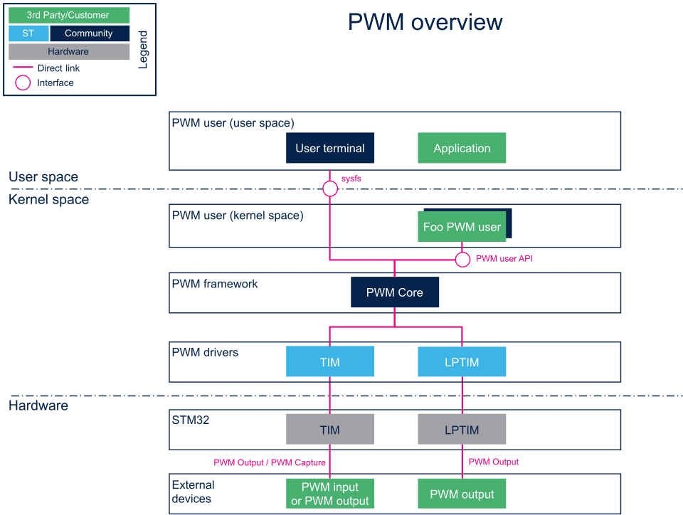
2.1. Component description[edit | edit source]
- PWM user (User space)
The user can use PWM sysfs interface, from a user terminal or a custom application, to control PWM device(s) from user space.
- PWM user (Kernel space)
User drivers can use PWM API to control PWM external device(s) from kernel space (such as back-light, vibrator, LED or fan drivers).
- PWM framework (Kernel space)
The PWM core provides sysfs interface and PWM API. They can be used to implement PWM user and PWM controller drivers.
- PWM drivers (Kernel space)
Provider drivers such as STM32 TIM Linux driver and STM32 LPTIM Linux driver that expose PWM controller(s) to the core.
- PWM hardware
PWM controller(s) such as TIM internal peripheral[1] and LPTIM internal peripheral[2] used to drive external PWM controlled devices.
2.2. API description[edit | edit source]
Documentation on PWM interface can be found under kernel Documentation/driver-api/pwm.rst[3]
2.2.1. Kernel PWM API[edit | edit source]
The main useful user API are the following:
- devm_pwm_get() or pwm_get() / pwm_put(): this API is used to look up, request, then free a PWM device.
- pwm_init_state(), pwm_get_state(), pwm_apply_state(): this API is used to initialize, retrieve and apply the current PWM device state.
- pwm_config(): this API updates the PWM device configuration (period and duty cycle).
- ...
2.2.2. Sysfs interface[edit | edit source]
In addition to Documentation/driver-api/pwm.rst[3], details on ABI are available in Documentation/ABI/testing/sysfs-class-pwm[4].
3. Configuration[edit | edit source]
3.1. Kernel configuration[edit | edit source]
Activate PWM framework in the kernel configuration through the Linux menuconfig tool, Menuconfig or how to configure kernel (CONFIG_PWM=y):
Device Drivers  --->
   [*] Pulse-Width Modulation (PWM) Support  --->
Activate PWM drivers for STM32 PWM drivers: STM32 TIM Linux driver and/or STM32 LPTIM Linux driver
3.2. Device tree configuration[edit | edit source]
- PWM generic DT bindings:
PWM DT bindings documentation[5] describes device tree properties related to standard PWM user nodes and PWM controller nodes.
- Detailed DT configuration for STM32 internal peripherals:
TIM device tree configuration and/or LPTIM device tree configuration
4. How to use the framework[edit | edit source]
PWM can be used either from the user or the kernel space.
4.1. How to use PWM with sysfs interface[edit | edit source]
The available PWM controllers are listed in sysfs:
ls /sys/class/pwm
pwmchip0
The number of channels per controller can be read in npwm (read-only)
cd /sys/class/pwm/pwmchip0
cat npwm
4
Each channel is exported (requested for sysfs activation) by writing the corresponding number in 'export'.
As an example, proceed as follows to export the first channel (TIMx_CH1, e.g. channel 0):
echo 0 > export
ls
device  export  npwm  power  pwm0  subsystem  uevent  unexport
The period and duty cycle must be configured before enabling any channel.
As an example, proceed as follows to set a period of 100 ms with a duty cycle of 60% on channel 0:
echo 100000000 > pwm0/period
echo 60000000 > pwm0/duty_cycle
echo 1 > pwm0/enable
The polarity can be inverted or set to normal by using the polarity entry:
echo "inversed" > pwm0/polarity
cat pwm0/polarity
inversed

echo "normal" > pwm0/polarity
cat pwm0/polarity
normal
4.2. How to use PWM capture with sysfs interface[edit | edit source]
PWM capture is available on some PWM controllers such as TIM internal peripheral[1] (see TIM configured in PWM input capture mode ).
# First export a channel (e.g. 0), then capture PWM input on it:
cd /sys/class/pwm/pwmchip0
echo 0 > export

cd pwm0
ls
capture  duty_cycle  enable  period  polarity  power  uevent

cat capture
10000 1002               # capture result is in nano-seconds, e.g.: 100KHz, 10% duty cycle
4.3. Example of PWM usage with kernel PWM API[edit | edit source]
Several in-kernel drivers use kernel PWM API. Below a few examples:
- pwm-beeper: drivers/input/misc/pwm-beeper.c[6] driver, Documentation/devicetree/bindings/input/pwm-beeper.yaml DT binding documentation.
- pwm-vibrator: drivers/input/misc/pwm-vibra.c[7] driver, Documentation/devicetree/bindings/input/pwm-vibrator.yaml DT binding documentation.
5. How to trace and debug the framework[edit | edit source]
5.1. How to monitor with debugfs[edit | edit source]
PWM usage can be monitored from debugfs 'pwm' entry. For example:
cd /sys/kernel/debug/
cat pwm
platform/44000000.timer:pwm, 4 PWM devices                                                               <-- One timer instance exposes 4 PWM channels.
 pwm-0   (sysfs               ): requested enabled period: 1000000 ns duty: 500000 ns polarity: normal   <-- Channel 0 has been exported, enabled and configured via sysfs
 pwm-1   ((null)              ): period: 0 ns duty: 0 ns polarity: normal
 pwm-2   ((null)              ): period: 0 ns duty: 0 ns polarity: normal                                <-- Other channels aren't used currently
 pwm-3   ((null)              ): period: 0 ns duty: 0 ns polarity: normal
5.2. Troubleshooting PWM capture[edit | edit source]
Here are some clues on how to debug possible errors in PWM capture mode.
See How to use PWM capture with sysfs interface as a pre-requisite.
cat capture
cat: capture: Connection timed out
This may be due to:
- the input signal isn't recognized as a PWM input (or there's no input signal to capture).
- a wrong alternate function number is used for the input pin configuration in the device-tree.
See "TIM configured in PWM input capture mode" for further details.
cat capture
cat: capture: Device or resource busy
This may be due to:
- a PWM channel on the same TIM instance is already running (in capture or output mode)
cat capture
cat: capture: No such device
This may be due to:
- the DMA isn't configured properly in the device-tree.
See "TIM configured in PWM input capture mode" for further details.
cat capture
cat: capture: Function not implemented
This may be due to:
- a wrong TIM instance is being used (e.g. "/sys/class/pwm/pwmchip/pwmchipN"), and it doesn't support capture (like LPTIM)
- the DMA support isn't enabled (CONFIG_DMA_ENGINE)
6. References[edit | edit source]
- ↑ 1.0 1.1 1.2 TIM internal peripheral
- ↑ LPTIM internal peripheral
- ↑ 3.0 3.1 Documentation/driver-api/pwm.rst , Pulse Width Modulation interface
- ↑ Documentation/ABI/testing/sysfs-class-pwm , Pulse Width Modulation ABI
- ↑ Documentation/devicetree/bindings/pwm/pwm.txt , PWM DT bindings documentation
- ↑ drivers/input/misc/pwm-beeper.c , Example to use kernel PWM API
- ↑ drivers/input/misc/pwm-vibra.c , Example to use kernel PWM API