Registered User mNo edit summary |
Registered User No edit summary |
||
| (43 intermediate revisions by 9 users not shown) | |||
| Line 1: | Line 1: | ||
{{ApplicableFor | |||
|MPUs list=STM32MP13x, STM32MP15x, STM32MP21x, STM32MP23x, STM32MP25x | |||
|MPUs checklist=STM32MP13x, STM32MP15x, STM32MP21x, STM32MP23x, STM32MP25x | |||
}} | |||
__FORCETOC__ | __FORCETOC__ | ||
== Generic boot sequence == | == Generic boot sequence == | ||
| Line 4: | Line 8: | ||
Starting Linux<sup>®</sup> on a processor is done in several steps that progressively initialize the platform peripherals and memories. These steps are | Starting Linux<sup>®</sup> on a processor is done in several steps that progressively initialize the platform peripherals and memories. These steps are | ||
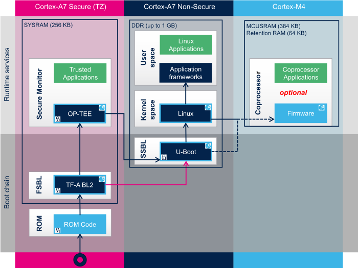
explained in the following paragraphs and illustrated by the diagram on the right, which also gives typical memory sizes for each stage. | explained in the following paragraphs and illustrated by the diagram on the right, which also gives typical memory sizes for each stage. | ||
[[File: Boot_chains_overview.png| | [[File: Boot_chains_overview.png|center|link=|Generic Linux boot chain]] | ||
==== ROM code ==== | ==== ROM code ==== | ||
The ROM code is a piece of software that takes its name from the read only memory (ROM) where it is stored. It fits in a few tens of Kbytes and maps its data in embedded RAM. It is the first code executed by the processor, and | The ROM code is a piece of software that takes its name from the read only memory (ROM) where it is stored. It fits in a few tens of Kbytes and maps its data in embedded RAM. It is the first code executed by the processor, and embeds all the logic needed to select the boot device (serial link or flash) from which the first-stage bootloader (FSBL) is loaded to the embedded RAM.<br> | ||
Most products require to trust the application that is running on the device and the ROM code is the first link in the chain of trust that must be established across all started components: this trust is established by authenticating the FSBL before starting it. In turn, the FSBL and each following component | Most products require to trust the application that is running on the device and the ROM code is the first link in the chain of trust that must be established across all started components: this trust is established by authenticating the FSBL before starting it. In turn, the FSBL and each following component authenticates the next one, up to a level defined by the product manufacturer. | ||
==== First stage | ==== First stage bootloader (FSBL) ==== | ||
Among other things, the first stage | Among other things, the first stage bootloader (FSBL) initializes (part of) the clock tree and the external RAM controller. Finally, the FSBL loads the second-stage bootloader (SSBL) into the external RAM and jumps to it.<br /> | ||
The [[TF-A overview|Trusted Firmware-A (TF-A)]] | The [[TF-A overview|Trusted Firmware-A (TF-A BL2)]] is FSBL for Cortex-A developed by TrustedFirmware.org community. | ||
==== Second-stage | ==== Second-stage bootloader (SSBL) ==== | ||
The second-stage | The second-stage bootloader (SSBL) runs in a wide RAM so it can implement complex features (such as, USB, Ethernet, display), that are very useful to make Linux kernel loading more flexible (from a storage device on USB or on a network), and user-friendly (by showing a splash screen to the user). [[U-Boot overview|U-Boot]] is commonly used as a Linux bootloader in embedded systems. | ||
==== Linux kernel space ==== | ==== Linux kernel space ==== | ||
The Linux kernel is started in the external memory and it initializes all the peripheral drivers that are needed on the platform. | The Linux kernel is started in the external memory, and it initializes all the peripheral drivers that are needed on the platform. | ||
==== Linux user space ==== | ===== Linux user space ===== | ||
Finally, the Linux kernel hands control to the user space starting the init process that runs all initialization actions described in the root file system (rootfs), including the application framework that exposes the user interface (UI) to the user.<br /> | Finally, the Linux kernel hands control to the user space starting the init process that runs all initialization actions described in the root file system (rootfs), including the application framework that exposes the user interface (UI) to the user.<br /> | ||
=== Other services start-up === | === Other services start-up === | ||
[[File: STM32MP boot chain.png | [[File: STM32MP boot chain.png|right|link=|STM32MP boot chain]] | ||
In addition to <span style="color:#FFFFFF; background:{{STDarkBlue}};"> Linux </span> startup, the boot chain also installs the secure monitor and may support coprocessor firmware loading. | In addition to <span style="color:#FFFFFF; background:{{STDarkBlue}};"> Linux </span> startup, the boot chain also installs the secure monitor and may support coprocessor firmware loading. | ||
<br /><br /> | <br /><br /> | ||
For instance, for the STM32MP15, the boot chain starts: | For instance, for the STM32MP15, the boot chain starts: | ||
* | * The <span style="color:#FFFFFF; background:{{STPink}};"> secure monitor </span>, supported by the Arm<sup>®</sup> Cortex<sup>®</sup>-A secure context (TrustZone). Examples of use of a secure monitor are user authentication, key storage, and tampering management. | ||
* | * The <span style="color:#FFFFFF; background:{{STLightBlue}};"> coprocessor </span> firmware, running on the Arm Cortex-M core. This can be used to offload real-time or low-power services. | ||
<br /> | <br /> | ||
The dotted lines in the diagram on the right mean that | The dotted lines in the diagram on the right mean that the <span style="color:#FFFFFF; background:{{STLightBlue}};"> coprocessor </span> can be started by the '''second stage bootloader (SSBL)''', known as “'''early boot'''”, or '''Linux kernel''' (by default). | ||
<br clear=all> | <br clear=all> | ||
== | == {{MicroprocessorDevice | device=1}} boot chain == | ||
{{:STM32MP1 boot chain overview}} | |||
=== | == {{MicroprocessorDevice | device=2}} boot chain == | ||
{{:STM32MP2 boot chain overview}} | |||
<noinclude> | |||
[[Category:Platform boot|0]] | |||
{{PublicationRequestId | 31755| 2024-07-22 | previous : 22726/ 2022-03-03}} | |||
</noinclude> | </noinclude> | ||
Latest revision as of 10:18, 7 October 2024
1. Generic boot sequence[edit | edit source]
1.1. Linux start-up[edit | edit source]
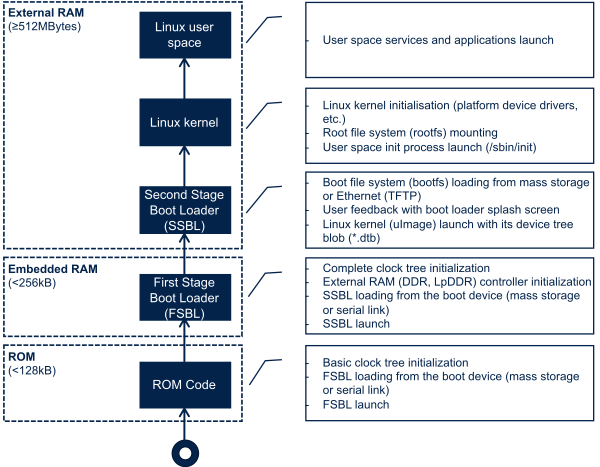
Starting Linux® on a processor is done in several steps that progressively initialize the platform peripherals and memories. These steps are explained in the following paragraphs and illustrated by the diagram on the right, which also gives typical memory sizes for each stage.
1.1.1. ROM code[edit | edit source]
The ROM code is a piece of software that takes its name from the read only memory (ROM) where it is stored. It fits in a few tens of Kbytes and maps its data in embedded RAM. It is the first code executed by the processor, and embeds all the logic needed to select the boot device (serial link or flash) from which the first-stage bootloader (FSBL) is loaded to the embedded RAM.
Most products require to trust the application that is running on the device and the ROM code is the first link in the chain of trust that must be established across all started components: this trust is established by authenticating the FSBL before starting it. In turn, the FSBL and each following component authenticates the next one, up to a level defined by the product manufacturer.
1.1.2. First stage bootloader (FSBL)[edit | edit source]
Among other things, the first stage bootloader (FSBL) initializes (part of) the clock tree and the external RAM controller. Finally, the FSBL loads the second-stage bootloader (SSBL) into the external RAM and jumps to it.
The Trusted Firmware-A (TF-A BL2) is FSBL for Cortex-A developed by TrustedFirmware.org community.
1.1.3. Second-stage bootloader (SSBL)[edit | edit source]
The second-stage bootloader (SSBL) runs in a wide RAM so it can implement complex features (such as, USB, Ethernet, display), that are very useful to make Linux kernel loading more flexible (from a storage device on USB or on a network), and user-friendly (by showing a splash screen to the user). U-Boot is commonly used as a Linux bootloader in embedded systems.
1.1.4. Linux kernel space[edit | edit source]
The Linux kernel is started in the external memory, and it initializes all the peripheral drivers that are needed on the platform.
1.1.4.1. Linux user space[edit | edit source]
Finally, the Linux kernel hands control to the user space starting the init process that runs all initialization actions described in the root file system (rootfs), including the application framework that exposes the user interface (UI) to the user.
1.2. Other services start-up[edit | edit source]
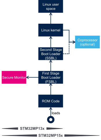
In addition to Linux startup, the boot chain also installs the secure monitor and may support coprocessor firmware loading.
For instance, for the STM32MP15, the boot chain starts:
- The secure monitor , supported by the Arm® Cortex®-A secure context (TrustZone). Examples of use of a secure monitor are user authentication, key storage, and tampering management.
- The coprocessor firmware, running on the Arm Cortex-M core. This can be used to offload real-time or low-power services.
The dotted lines in the diagram on the right mean that the coprocessor can be started by the second stage bootloader (SSBL), known as “early boot”, or Linux kernel (by default).
2. STM32MP1 series boot chain[edit | edit source]
2.1. Diagram frames and legend[edit | edit source]
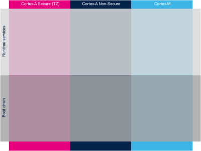
The hardware execution contexts are shown with vertical frames in the boot diagrams:
- The Arm Cortex-A secure context, in pink.
- The Arm Cortex-A nonsecure context, in dark blue.
- The Arm Cortex-M context, in light blue, for STM32MP15x lines
 only.
only.
The horizontal frame in:
- The bottom part shows the boot chain.
- The top part shows the runtime services, that are installed by the boot chain.

The legend on the right illustrates how the information about the various components shown in the frames are involved in the boot process. These are highlighted as follows:
- The box color shows the component source code origin.
- The arrows show the loading and calling actions between the components.
- The Cube logo is used on the top right corner of components that can be configured via STM32CubeMX.
- The lock shows the components that can be authenticated during the boot process.
2.2. STM32MP13 boot chain[edit | edit source]
2.2.1. Overview[edit | edit source]
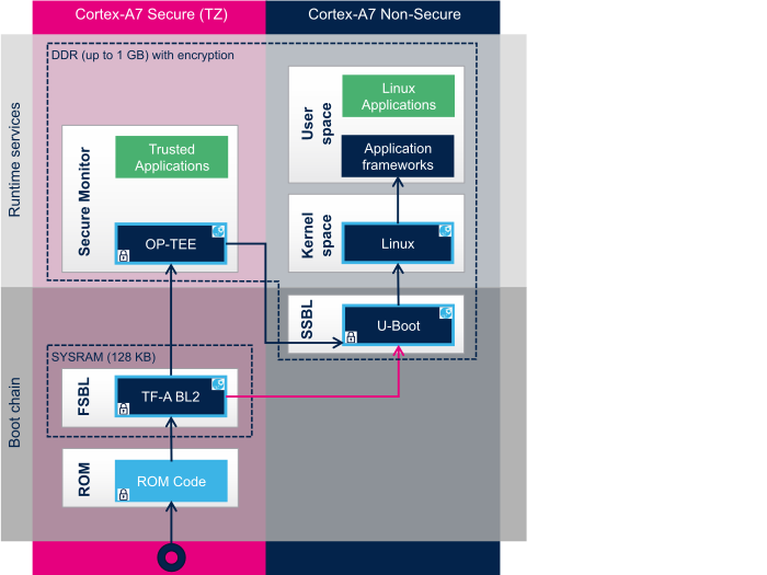
STM32MP13 boot chain uses Trusted Firmware-A (TF-A) as the FSBL in order to fulfill all the requirements for security-sensitive customers, and it uses U-Boot as the SSBL. Note that this boot chain can run on any STM32MP13 device security variant (that is, with or without the secure boot).
Refer to the security overview for an introduction of the secure features available on STM32MP13, from the secure boot up to trusted applications execution.
2.2.2. ROM code[edit | edit source]
The ROM code starts the processor in secure mode. It supports the FSBL authentication and decryption.
2.2.3. First stage bootloader (FSBL)[edit | edit source]
The FSBL is executed from the SYSRAM.
Among other things, this bootloader initializes (part of) the clock tree and the DDR controller. Finally, the FSBL loads the second-stage bootloader (SSBL) into the DDR external RAM and jumps to it.
The bootloader stage 2, so called TF-A BL2, is the Trusted Firmware-A (TF-A) binary used as FSBL on STM32MP13.
2.2.4. Second stage bootloader (SSBL)[edit | edit source]
U-Boot is commonly used as a bootloader in embedded software and it is the one used on STM32MP13.
2.2.5. Linux[edit | edit source]
Linux® OS is loaded in DDR by U-Boot and executed in the nonsecure context.
2.2.6. Secure OS / Secure monitor[edit | edit source]
The Cortex-A7 secure world supports OP-TEE secure OS.
2.3. STM32MP15 boot chain[edit | edit source]
2.3.1. Overview[edit | edit source]
STM32MP15 boot chain uses Trusted Firmware-A (TF-A) as the FSBL in order to fulfill all the requirements for security-sensitive customers, and it uses U-Boot as the SSBL. Note that the authentication is optional with this boot chain, so it can run on any STM32MP15 device security variant (that is, with or without the secure boot).
Refer to the security overview for an introduction of the secure features available on STM32MP15, from the secure boot up to trusted applications execution.
Note:
- The STM32MP15 coprocessor can be started at the SSBL level by the U-Boot early boot feature or, later, by the Linux remoteproc framework, depending on the application startup time-targets.
2.3.2. ROM code[edit | edit source]
The ROM code starts the processor in secure mode. It supports the FSBL authentication and offers authentication services to the FSBL.
2.3.3. First stage bootloader (FSBL)[edit | edit source]
The FSBL is executed from the SYSRAM.
Among other things, this bootloader initializes (part of) the clock tree and the DDR controller. Finally, the FSBL loads the second-stage bootloader (SSBL) into the DDR external RAM and jumps to it.
The bootloader stage 2, so called TF-A BL2, is the Trusted Firmware-A (TF-A) binary used as FSBL on STM32MP15.
2.3.4. Second stage bootloader (SSBL)[edit | edit source]
U-Boot is commonly used as a bootloader in embedded software and it is the one used on STM32MP15.
2.3.5. Linux[edit | edit source]
Linux® OS is loaded in DDR by U-Boot and executed in the nonsecure context.
2.3.6. Secure OS / Secure monitor[edit | edit source]
The Cortex-A7 secure world supports OP-TEE secure OS.
2.3.7. Coprocessor firmware[edit | edit source]
The coprocessor STM32Cube firmware can be started at the SSBL level by U-Boot with the remoteproc feature (rproc command) or, later, by Linux remoteproc framework, depending on the application startup time-targets.
3. STM32MP2 series boot chain[edit | edit source]
3.1. Diagram frames and legend[edit | edit source]
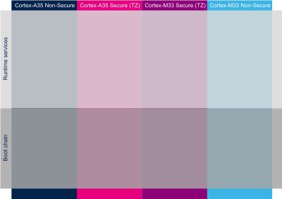
The hardware execution contexts are shown with vertical frames in the boot diagrams:
- The Arm Cortex-A secure context, in pink.
- The Arm Cortex-A nonsecure context, in dark blue.
- The Arm Cortex-M secure context, in light blue.
- The Arm Cortex-M nonsecure context, in light blue.
The horizontal frame in:
- The bottom part shows the boot chain.
- The top part shows the runtime services, that are installed by the boot chain.

The legend on the right illustrates how the information about the various components shown in the frames are involved in the boot process. These are highlighted as follows:
- The box color shows the component source code origin.
- The arrows show the loading and calling actions between the components.
- The Cube logo is used on the top right corner of components that can be configured via STM32CubeMX.
- The lock shows the components that can be authenticated during the boot process.
3.2. STM32MP2 Cortex-A35 main processor boot chain[edit | edit source]
3.2.1. Overview[edit | edit source]
When Cortex-A35 main processor mode is selected, the Cortex-A35 is booting first. Cortex-M33 is kept under reset by hardware until application request to start it.
STM32MP2 boot chain uses Trusted Firmware-A (TF-A) as the FSBL in order to fulfill all the requirements for security-sensitive customers, and it uses U-Boot as the SSBL executing in Cortex-A35 nonsecure context.
Note that the authentication is optional with this boot chain, so it can run on any STM32MP2 device security variant (that is, with or without the secure boot).
Refer to the security overview for an introduction of the secure features available on STM32MP2, from the secure boot up to trusted applications execution.
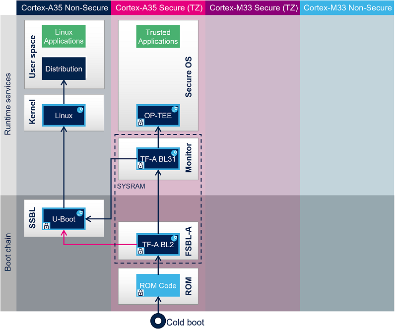
Once system is initialized (clock tree, regulators, system firewall) by OP-TEE secure OS, it is possible to start Cortex-M33 in coprocessor at SSBL level by the U-Boot early boot feature or, later, by the Linux remoteproc framework, depending on the application startup time-targets.
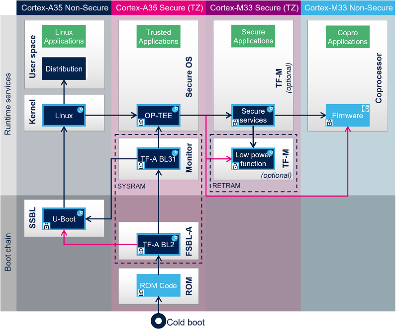
Cortex-M33 coprocessor management could directly be done by U-Boot or Linux kernel in case of non-authenticated Cortex-M33 firmware or could rely on OP-TEE remoteproc trusted application in case of authenticated Cortex-M33 firmware.
Cortex-M33 firmware could be made up of different parts depending on customer product requirements:
- Cortex-M33 nonsecure: STM32 Cube for application.
- Cortex-M33 secure: TF-M secure OS for runtime secure services (optional).
- Cortex-M33 secure: low power functions for Cortex-M33 low power entry and exit management (optional).
The following figure shows an authenticated Cortex-M33 firmware load and start by Linux kernel through OP-TEE remoteproc TA.
3.2.2. ROM code[edit | edit source]
The ROM code starts the processor in secure mode. It supports the FSBL authentication and decryption.
3.2.3. First stage bootloader (FSBL)[edit | edit source]
The FSBL is executed from the SYSRAM.
Among other things, this bootloader initializes (part of) the clock tree and the DDR controller.
The FSBL loads (and optionally authenticates) the secure monitor, the secure OS and the second-stage bootloader (SSBL) into the DDR external RAM and jumps to secure monitor.
Trusted Firmware-A (TF-A) BL2 is used as FSBL on STM32MP2 series.
3.2.4. Second stage bootloader (SSBL)[edit | edit source]
U-Boot is commonly used as a bootloader in embedded software and it is the one used on STM32 Arm® Cortex® MPUs ![]() .
.
3.2.5. Linux[edit | edit source]
Linux® OS is loaded in DDR by U-Boot and executed in the nonsecure context.
3.2.6. Secure monitor[edit | edit source]
The Cortex-A35 secure world (EL3) supports TF-A BL31 secure monitor. Its role is to manage transitions between Cortex-A35 secure and nonsecure contexts and Cortex-A35 cluster low power states.
3.2.7. Secure OS[edit | edit source]
The Cortex-A35 secure world supports OP-TEE secure OS.
3.2.8. Coprocessor firmware[edit | edit source]
The coprocessor STM32Cube firmware can be started at the SSBL level by U-Boot with the remoteproc feature (rproc command) or, later, by Linux remoteproc framework, depending on the application startup time-targets.
Thanks to a specific OP-TEE trusted application (TA) running on the Arm® TrustZone and to the Resource Isolation Framework, it is possible to authenticate the Cortex®-M33 firmware, and install it on isolated memory region to ensure its integrity during the execution. For details, please refer to How_to_protect_the_coprocessor_firmware article.