1. Article purpose[edit | edit source]
The purpose of this article is to:
- briefly introduce the FMC peripheral and its main features,
- indicate the peripheral instances assignment at boot time and their assignment at runtime (including whether instances can be allocated to secure contexts),
- list the software frameworks and drivers managing the peripheral,
- explain how to configure the peripheral.
2. Peripheral overview[edit | edit source]
The FMC peripheral includes two memory controllers:
- The NOR/PSRAM memory controller
- The NAND memory controller.
Refer to the STM32 MPU reference manuals for the complete list of features, and to the software frameworks and drivers, introduced below, to see which features are implemented.
2.1. NOR/PSRAM memory controller (or external bus interface controller)[edit | edit source]
The FMC NOR/PSRAM memory controller is used to interface static memory devices, but it is also used to interface Ethernet devices, LCD devices, and so on.
The FMC NOR/PSRAM controller generates the appropriate signal timings to drive the following types of memories:
- Asynchronous SRAM, FRAM and ROM
- 8 bits
- 16 bits
- PSRAM (CellularRAM™)
- Asynchronous mode
- Burst mode for synchronous accesses with configurable option to split burst access when crossing boundary page for CRAM 1.5.
- Multiplexed or non-multiplexed
- NOR Flash memory
- Asynchronous mode
- Burst mode for synchronous accesses
- Multiplexed or non-multiplexed
The FMC NOR/PSRAM controller supports a wide range of devices through programmable timings.
Among those programmable timings, there are:
- Programmable wait states (up to 15)
- Programmable bus turnaround cycles (up to 15)
- Programmable output enable and write enable delays (up to 15)
- Independent read and write timings and protocol to support the widest variety of memories and timings
- Programmable continuous clock output.
The FMC NOR/PSRAM controller also supports up to four external devices.
2.2. NAND Flash controller[edit | edit source]
The FMC NAND Flash controller is used to interface STM32 MPU with SLC 8-bit or 16-bit NAND Flash memory devices.
The FMC NAND Flash controller supports:
- Programmable error correction capability (ECC) using BCH8 code, BCH4 code or Hamming code
- Programmable page size of 2048, 4096 and 8192 bytes
- Programmable memory timings
- Multiple dice per package.
2.3. FMC access protection[edit | edit source]
On STM32MP2 series, FMC is a RIF-aware peripheral. It embeds dedicated RIF protection units which follow firewall rules described in Resource Isolation Framework overview. The FMC protected resources are:
- FMC_R0: common registers
- FMC_R1: NOR/PSRAM controller for chip select NE1
- FMC_R2: NOR/PSRAM controller for chip select NE2
- FMC_R3: NOR/PSRAM controller for chip select NE3
- FMC_R4: NOR/PSRAM controller for chip select NE4
- FMC_R5: NAND controller
3. Peripheral usage[edit | edit source]
This chapter is applicable in the scope of the OpenSTLinux BSP running on the Arm® Cortex®-A processor(s), and the STM32CubeMPU Package running on the Arm® Cortex®-M processor.
3.1. Boot time assignment[edit | edit source]
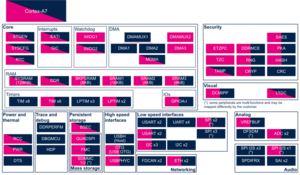
3.1.1. On STM32MP1 series[edit | edit source]
The FMC NAND Flash controller is the boot device that supports serial boot for Flash programming with STM32CubeProgrammer.
Click on ![]() to expand or collapse the legend...
to expand or collapse the legend...
Check boxes illustrate the possible peripheral allocations supported by the OpenSTLinux BSP:
- ⬚ means that the peripheral can be assigned to the given boot time context, but this configuration is not supported in OpenSTLinux BSP.
- ☐ means that the peripheral can be assigned to the given boot time context.
- ☑ means that the peripheral is assigned by default to the given boot time context and that the peripheral is mandatory for the OpenSTLinux BSP.
- ✓ is used for system peripherals that cannot be unchecked because they are hardware connected in the device.
The present chapter describes STMicroelectronics recommendations or choice of implementation. Additional possibilities might be described in STM32 MPU reference manuals.
| Domain | Peripheral | Boot time allocation | Comment | |||
|---|---|---|---|---|---|---|
| Instance | Cortex-A7 secure (ROM code) |
Cortex-A7 secure (TF-A BL2) |
Cortex-A7 nonsecure (U-Boot) | |||
| Mass storage | FMC | FMC | ☐ | ☐ | ☐ | |
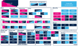
3.1.2. On STM32MP2 series[edit | edit source]
Click on ![]() to expand or collapse the legend...
to expand or collapse the legend...
Check boxes illustrate the possible peripheral allocations supported by the OpenSTLinux BSP:
- ⬚ means that the peripheral can be assigned to the given boot time context, but this configuration is not supported in OpenSTLinux BSP.
- ☐ means that the peripheral can be assigned to the given boot time context.
- ☑ means that the peripheral is assigned by default to the given boot time context and that the peripheral is mandatory for the OpenSTLinux BSP.
- ✓ is used for system peripherals that cannot be unchecked because they are hardware connected in the device.
The present chapter describes STMicroelectronics recommendations or choice of implementation. Additional possibilities might be described in STM32 MPU reference manuals.
| Domain | Peripheral | Boot time allocation | Comment | |||
|---|---|---|---|---|---|---|
| Instance | Cortex-A35 secure (ROM code) |
Cortex-A35 secure (TF-A BL2) |
Cortex-A35 nonsecure (U-Boot) | |||
| Mass storage | FMC |
FMC | ☐ | ☐ | ☐ | Shareable at internal peripheral level thanks to the RIF: see the boot time allocation per feature |
The below table shows the possible boot time allocations for the features of the FMC instance.
| Feature | Boot time allocation |
Comment | ||
|---|---|---|---|---|
| Cortex-A35 secure (ROM code) |
Cortex-A35 secure (TF-A BL2) |
Cortex-A35 nonsecure (U-Boot) | ||
| FMC_CFGR | ☐ | ☐ | ☐ | |
| FMC_NOR/PSRAM1 | ⬚ | ☐ | ||
| FMC_NOR/PSRAM2 | ⬚ | ☐ | ||
| FMC_NOR/PSRAM3 | ⬚ | ☐ | ||
| FMC_NOR/PSRAM4 | ⬚ | ☐ | ||
| FMC_NAND | ☐ | ☐ | ☐ | |
3.2. Runtime assignment[edit | edit source]
3.2.1. On STM32MP13x lines  [edit | edit source]
Click on ![]() to expand or collapse the legend...
to expand or collapse the legend...
Check boxes illustrate the possible peripheral allocations supported by the OpenSTLinux BSP:
- ⬚ means that the peripheral can be assigned to the given runtime context, but this configuration is not supported in OpenSTLinux BSP.
- ☐ means that the peripheral can be assigned to the given runtime context.
- ☑ means that the peripheral is assigned by default to the given runtime context and that the peripheral is mandatory for the OpenSTLinux BSP.
- ✓ is used for system peripherals that cannot be unchecked because they are hardware connected in the device.
Refer to How to assign an internal peripheral to an execution context for more information on how to assign peripherals manually or via STM32CubeMX.
The present chapter describes STMicroelectronics recommendations or choice of implementation. Additional possibilities might be described in STM32MP13 reference manuals.
| Domain | Peripheral | Runtime allocation | Comment | ||
|---|---|---|---|---|---|
| Instance | Cortex-A7 secure (OP-TEE) |
Cortex-A7 nonsecure (Linux) | |||
| Mass storage | FMC | FMC | ⬚ | ☐ | Assignment (single choice) |
3.2.2. On STM32MP15x lines [edit | edit source]
Click on ![]() to expand or collapse the legend...
to expand or collapse the legend...
Check boxes illustrate the possible peripheral allocations supported by the OpenSTLinux BSP:
- ⬚ means that the peripheral can be assigned to the given runtime context, but this configuration is not supported in OpenSTLinux BSP.
- ☐ means that the peripheral can be assigned to the given runtime context.
- ☑ means that the peripheral is assigned by default to the given runtime context and that the peripheral is mandatory for the OpenSTLinux BSP.
- ✓ is used for system peripherals that cannot be unchecked because they are hardware connected in the device.
Refer to How to assign an internal peripheral to an execution context for more information on how to assign peripherals manually or via STM32CubeMX.
The present chapter describes STMicroelectronics recommendations or choice of implementation. Additional possiblities might be described in STM32MP15 reference manuals.
| Domain | Peripheral | Runtime allocation | Comment | |||
|---|---|---|---|---|---|---|
| Instance | Cortex-A7 secure (OP-TEE) |
Cortex-A7 nonsecure (Linux) |
Cortex-M4 (STM32Cube) | |||
| Mass storage | FMC | FMC | ☐ | ☐ | Assignment (single choice) | |
3.2.3. On STM32MP21x lines [edit | edit source]
Click on ![]() to expand or collapse the legend...
to expand or collapse the legend...
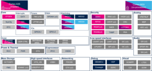
Check boxes illustrate the possible peripheral allocations supported by the OpenSTLinux BSP:
- ⬚ means that the peripheral can be assigned to the given runtime context, but this configuration is not supported in OpenSTLinux BSP.
- ☐ means that the peripheral can be assigned to the given runtime context.
- ☑ means that the peripheral is assigned by default to the given runtime context and that the peripheral is mandatory for the OpenSTLinux BSP.
- ✓ is used for system peripherals that cannot be unchecked because they are hardware connected in the device.
Refer to How to assign an internal peripheral to an execution context for more information on how to assign peripherals manually or via STM32CubeMX.
The present chapter describes STMicroelectronics recommendations or choice of implementation. Additional possibilities might be described in STM32MP21 reference manuals.
| Domain | Peripheral | Runtime allocation | Comment | ||||
|---|---|---|---|---|---|---|---|
| Instance | Cortex-A35 secure (OP-TEE / TF-A BL31) |
Cortex-A35 nonsecure (Linux) |
Cortex-M33 secure (TF-M) |
Cortex-M33 nonsecure (STM32Cube) | |||
| Mass storage | FMC |
FMC | ☐ | ☐ | ☐ | ☐ | Shareable at internal peripheral level thanks to the RIF: see the runtime allocation per feature |
The below table shows the possible runtime allocations for the features of the FMC instance.
| Feature | Runtime allocation |
Comment | |||
|---|---|---|---|---|---|
| Cortex-A35 secure (OP-TEE / TF-A BL31) |
Cortex-A35 nonsecure (Linux) |
Cortex-M33 secure (TF-M) |
Cortex-M33 nonsecure (STM32Cube) | ||
| FMC_CFGR | ☐OP-TEE | ☐ | ☐ | ☐ | |
| FMC_NOR/PSRAM1 | ⬚OP-TEE | ☐ | ⬚ | ☐ | |
| FMC_NOR/PSRAM2 | ⬚OP-TEE | ☐ | ⬚ | ☐ | |
| FMC_NOR/PSRAM3 | ⬚OP-TEE | ☐ | ⬚ | ☐ | |
| FMC_NOR/PSRAM4 | ⬚OP-TEE | ☐ | ⬚ | ☐ | |
| FMC_NAND | ⬚OP-TEE | ☐ | ⬚ | ⬚ | |
3.2.4. On STM32MP23x lines [edit | edit source]
Click on ![]() to expand or collapse the legend...
to expand or collapse the legend...
Check boxes illustrate the possible peripheral allocations supported by the OpenSTLinux BSP:
- ⬚ means that the peripheral can be assigned to the given runtime context, but this configuration is not supported in OpenSTLinux BSP.
- ☐ means that the peripheral can be assigned to the given runtime context.
- ☑ means that the peripheral is assigned by default to the given runtime context and that the peripheral is mandatory for the OpenSTLinux BSP.
- ✓ is used for system peripherals that cannot be unchecked because they are hardware connected in the device.
Refer to How to assign an internal peripheral to an execution context for more information on how to assign peripherals manually or via STM32CubeMX.
The present chapter describes STMicroelectronics recommendations or choice of implementation. Additional possibilities might be described in STM32MP23 reference manuals.
| Domain | Peripheral | Runtime allocation | Comment | ||||
|---|---|---|---|---|---|---|---|
| Instance | Cortex-A35 secure (OP-TEE / TF-A BL31) |
Cortex-A35 nonsecure (Linux) |
Cortex-M33 secure (TF-M) |
Cortex-M33 nonsecure (STM32Cube) | |||
| Mass storage | FMC |
FMC | ☐ | ☐ | ☐ | ☐ | Shareable at internal peripheral level thanks to the RIF: see the runtime allocation per feature |
The below table shows the possible runtime allocations for the features of the FMC instance.
| Feature | Runtime allocation |
Comment | |||
|---|---|---|---|---|---|
| Cortex-A35 secure (OP-TEE / TF-A BL31) |
Cortex-A35 nonsecure (Linux) |
Cortex-M33 secure (TF-M) |
Cortex-M33 nonsecure (STM32Cube) | ||
| FMC_CFGR | ☐OP-TEE | ☐ | ☐ | ☐ | |
| FMC_NOR/PSRAM1 | ⬚OP-TEE | ☐ | ⬚ | ☐ | |
| FMC_NOR/PSRAM2 | ⬚OP-TEE | ☐ | ⬚ | ☐ | |
| FMC_NOR/PSRAM3 | ⬚OP-TEE | ☐ | ⬚ | ☐ | |
| FMC_NOR/PSRAM4 | ⬚OP-TEE | ☐ | ⬚ | ☐ | |
| FMC_NAND | ⬚OP-TEE | ☐ | ⬚ | ⬚ | |
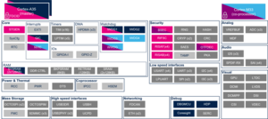
3.2.5. On STM32MP25x lines [edit | edit source]
Click on ![]() to expand or collapse the legend...
to expand or collapse the legend...
Check boxes illustrate the possible peripheral allocations supported by the OpenSTLinux BSP:
- ⬚ means that the peripheral can be assigned to the given runtime context, but this configuration is not supported in OpenSTLinux BSP.
- ☐ means that the peripheral can be assigned to the given runtime context.
- ☑ means that the peripheral is assigned by default to the given runtime context and that the peripheral is mandatory for the OpenSTLinux BSP.
- ✓ is used for system peripherals that cannot be unchecked because they are hardware connected in the device.
Refer to How to assign an internal peripheral to an execution context for more information on how to assign peripherals manually or via STM32CubeMX.
The present chapter describes STMicroelectronics recommendations or choice of implementation. Additional possibilities might be described in STM32MP25 reference manuals.
| Domain | Peripheral | Runtime allocation | Comment | |||||
|---|---|---|---|---|---|---|---|---|
| Instance | Cortex-A35 secure (OP-TEE / TF-A BL31) |
Cortex-A35 nonsecure (Linux) |
Cortex-M33 secure (TF-M) |
Cortex-M33 nonsecure (STM32Cube) |
Cortex-M0+ (STM32Cube) | |||
| Mass storage | FMC |
FMC | ☐ | ☐ | ☐ | ☐ | ☐ | Shareable at internal peripheral level thanks to the RIF: see the runtime allocation per feature |
The below table shows the possible runtime allocations for the features of the FMC instance.
| Feature | Runtime allocation |
Comment | ||||
|---|---|---|---|---|---|---|
| Cortex-A35 secure (OP-TEE / TF-A BL31) |
Cortex-A35 nonsecure (Linux) |
Cortex-M33 secure (TF-M) |
Cortex-M33 nonsecure (STM32Cube) |
Cortex-M0+ (STM32Cube) | ||
| FMC_CFGR | ☐OP-TEE | ☐ | ☐ | ☐ | ||
| FMC_NOR/PSRAM1 | ⬚OP-TEE | ☐ | ⬚ | ☐ | ||
| FMC_NOR/PSRAM2 | ⬚OP-TEE | ☐ | ⬚ | ☐ | ||
| FMC_NOR/PSRAM3 | ⬚OP-TEE | ☐ | ⬚ | ☐ | ||
| FMC_NOR/PSRAM4 | ⬚OP-TEE | ☐ | ⬚ | ☐ | ||
| FMC_NAND | ⬚OP-TEE | ☐ | ⬚ | ⬚ | ||
4. Software frameworks and drivers[edit | edit source]
Below are listed the software frameworks and drivers managing the FMC peripheral for the embedded software components listed in the above tables.
- Linux®: MTD framework and drivers (drivers/mtd/nand/raw/stm32_fmc2_nand.c , drivers/memory/stm32-fmc2-ebi.c )
- STM32Cube: FMC HAL driver
- TF-A BL2: MTD framework (drivers/mtd/nand/ ) and driver (drivers/st/fmc/stm32_fmc2_nand.c )
- U-Boot: MTD framework (drivers/mtd/nand/raw/ ) and drivers (drivers/mtd/nand/raw/stm32_fmc2_nand.c , drivers/memory/stm32-fmc2-ebi.c )
- OP-TEE: driver (core/drivers/stm32_fmc.c )
5. How to assign and configure the peripheral[edit | edit source]
The peripheral assignment can be done via the STM32CubeMX graphical tool (and manually completed if needed).
This tool also helps to configure the peripheral:
- partial device trees (pin control and clock tree) generation for the OpenSTLinux software components,
- HAL initialization code generation for the STM32CubeMPU Package.
The configuration is applied by the firmware running in the context in which the peripheral is assigned.
For Linux kernel configuration, please refer to FMC device tree configuration.
Arm® is a registered trademark of Arm Limited (or its subsidiaries) in the US and/or elsewhere. ![]()
Arm® is a registered trademark of Arm Limited (or its subsidiaries) in the US and/or elsewhere. ![]()