Registered User mNo edit summary |
Registered User mNo edit summary |
||
| Line 2: | Line 2: | ||
== Board overview == | == Board overview == | ||
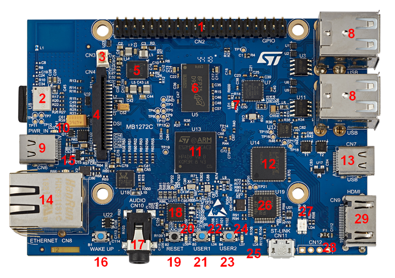
'''MB1272 motherboard STM32MP157x 12x12 with PMIC and DDR3''', revision C-0.1: part of the | '''MB1272 motherboard STM32MP157x 12x12 with PMIC and DDR3''', revision C-0.1: part of the S{{Board | type=157x-DKx}}. | ||
Note that: | Note that: | ||
* MB1272 for | * MB1272 for the '''{{Board | type=157A-DK1 | name=short}}''' and '''{{Board | type=157D-DK1 | name=short}}''' Discovery kits doesn't include the "WLAN + Bluetooth" component (muRata LBEE5KL1DX) | ||
* MB1272 for | * MB1272 for '''{{Board | type=157C-DK2 | name=short}}''' and '''{{Board | type=157F-DK2 | name=short}}''' Discovery kits includes the "WLAN + Bluetooth" component (Murata LBEE5KL1DX) | ||
{{ | {{ | ||
ImageMap|Image:MB1272_front_side.png {{!}} thumb{{!}} 800px {{!}} center{{!}} MB1272 front side (picture not contractual) | ImageMap|Image:MB1272_front_side.png {{!}} thumb{{!}} 800px {{!}} center{{!}} MB1272 front side (picture not contractual) | ||
rect 322 48 814 130 [[#GPIO | GPIO expansion]] | rect 322 48 814 130 [[#GPIO | GPIO expansion]] | ||
rect 80 243 151 310 [[#WLAN BT | WLAN + Bluetooth (muRata LBEE5KL1DX): only for | rect 80 243 151 310 [[#WLAN BT | WLAN + Bluetooth (muRata LBEE5KL1DX): only for only for STM32MP157x-DK2 Discovery kits]] | ||
rect 238 130 322 193 [[#Battery | Backup battery connector]] | rect 238 130 322 193 [[#Battery | Backup battery connector]] | ||
rect 238 193 322 454 [[#DSI | DSI LCD connector]] | rect 238 193 322 454 [[#DSI | DSI LCD connector]] | ||
Revision as of 11:51, 15 June 2020
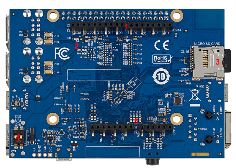
MB1272 board overview.
1. Board overview[edit | edit source]
MB1272 motherboard STM32MP157x 12x12 with PMIC and DDR3, revision C-0.1: part of the SSTM32MP157x-DKx Discovery kit ![]() .
.
Note that:
- MB1272 for the STM32MP157A-DK1
 and STM32MP157D-DK1
  Discovery kits doesn't include the "WLAN + Bluetooth" component (muRata LBEE5KL1DX)
 - MB1272 for STM32MP157C-DK2
 and STM32MP157F-DK2
  Discovery kits includes the "WLAN + Bluetooth" component (Murata LBEE5KL1DX)
Details of some LEDs:
- LD1: red if USB type A connection established
- LD2: green if power connection established
- LD3: green flashing the Ethernet connection established
- LD4: red flashing if ST-LINK/V2-1 connection not established, else green
- LD5, LD6, LD7, LD8: some user LEDs are used to reflect the system activity, whereas the others are left free and can be directly used by the application, as explained in the LEDs and buttons on STM32 MPU boards article
2. Links[edit | edit source]

