1. Article purpose[edit | edit source]
This article gives an example of high-rate transfers of data chunks from the Arm® Cortex®-M core to the Arm® Cortex®-A core.
2. Introduction[edit | edit source]
Relying on a logic analyzer sample, this article describes the mechanism and the software implemented to perform high-rate transfers. In this example, the Arm® Cortex®-M core is used to perform continuously:
- real-time operations
- simple data algorithm (masking bit)
- transfer of the resulting data to the Arm® Cortex®-A
Depending on the frequency sampling, the data is transferred using:
- either direct buffer exchange mode
- TTY RPMsg channel for control and data transfer
- low sampling frequency (less than or equal to 2 MHz)
- or indirect buffer exchange mode
- transfer using DDR buffers requiring:
- contiguous memory allocation in DDR memory
- Arm® Cortex®-M awareness of the physical address and size of the memory buffers
- mmaping of buffers to enable Linux®; user land application access to them
- rpmsg_sdb (shared data buffer) Linux® driver, developed to take care of DDR constraints. For details on this buffer exchange mechanisms, refer to the "rpmsg_sdb driver" chapter
- TTY RPMsg channel for control (especially to exchange references to the buffers between the processors)
- high sampling frequency (more than 2 MHz)
- transfer using DDR buffers requiring:
| The 2-MHz threshold indicated above between the direct buffer exchange mode and the indirect buffer exchange mode is just an indication that might varies depending on the use case (and especially on the loading of the system). >br>
See Usage chapter for example of kernel message indicating that the limit is reached. |
3. Example of context description[edit | edit source]
Let us implement a logic analyzer running on the STM32MP1 discovery kit.
From the user interface, press the START button to start the logic analyzer sampling. The logic analyzer samples GPIO PORT E bits 8 to 14, which are present on the Arduino connector. They correspond to 7 bits. The 8th bit will be reset by M4 algorithm.
The number of received data is displayed on the screen as bytes and megabytes.
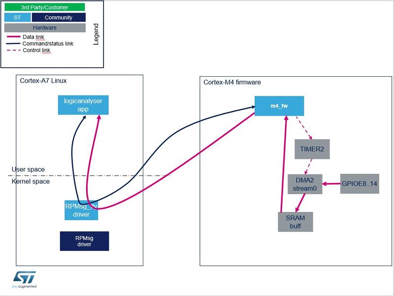
4. Example of static architecture for exchanging data buffers[edit | edit source]
The example of data buffer exchange includes:
- a Arm® Cortex®-M firmware
- a Linux® user land application
- a Linux® rpmsg_tty driver
- a Linux® rpmsg_sdb (shared data buffer) driver
Note that there is a direct correspondence between the sampling frequency and the data flow rate: thus, a sampling frequency of 8 MHz means a data flow rate of 8 MB/s (megabytes per second).
Data flow for low sampling frequency: the direct buffer exchange mode
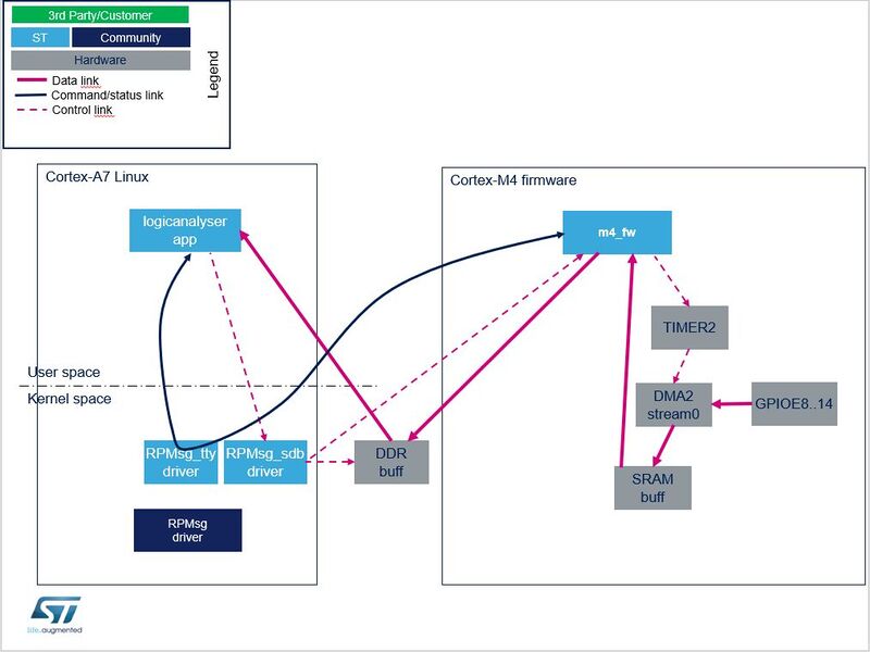
Data flow for high sampling frequency: the indirect buffer exchange mode (a.k.a. large data buffers exchange)
5. Arm Cortex-M firmware[edit | edit source]
The Arm® Cortex®-M firmware is responsible for:
- receiving a command giving of the number of DDR buffers through the TTY RPMsg channel, from the Linux® application.
- receiving messages containing the physical address and size of DDR buffer(s), from the Linux® rpmsg_sdb driver; These DDR buffers are always allocated, during the initialisation step, even if they are only used when the high sampling frequency (see below).
- receiving a command Start/Stop sampling (including sampling frequency) through the TTY RPMsg channel, from the Linux®application.
- On start request:
- sampling the data at the requested sampling frequency thanks to DMA2 stream0 from GPIOE to SRAM buffers
- masking and transferring data buffers from SRAM to Linux® application
- thanks to TTY over RPMSG buffer by packet of 256 bytes, for low sampling frequency
- thanks to copy to DDR buffer by packet of 1024 bytes, for high sampling frequency, and informing the Arm® Cortex®-A user interface (through the SDB RPMsg channel) when a DDR buffer of 1 Mbyte is filled, and roll to next DDR buffer
6. Linux user land application[edit | edit source]
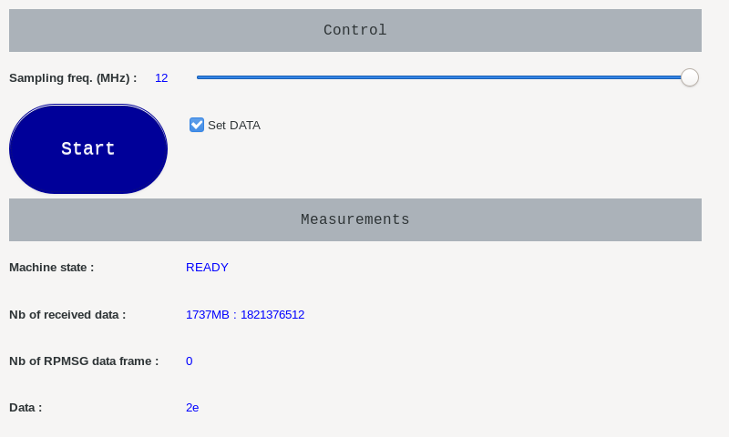
The Arm® Cortex®-A Linux® application includes a GTK user interface.
It allows controlling:
- the sampling frequency
- the start / stop of the sampling
- the data to be sampled thanks to "Set data" notch UI widget
The user interface displays:
- statistics: the number of data received by the user interface, as bytes and Mbytes
- the first data of every new received megabyte
7. Linux drivers[edit | edit source]
7.1. rpmsg_tty driver[edit | edit source]
The rpmsg_tty driver[1] simulates a serial link for communication between the Arm® Cortex®-M firmware and the Arm® Cortex®-A user land application. See also the Linux RPMsg framework overview article for information about the Linux® Remote Processor Messaging (RPMsg) framework.
7.2. rpmsg_sdb driver[edit | edit source]
The RPMsg shared data buffer (SDB)[2] driver example is in charge of:
- allocating large buffers in contiguous memory (DDR) and memory mapping them (mmap) for use by an application
- implementing the RPMsg service to share buffer information (address, size) with the remote processor
- sending events to a Linux® application (relying on the eventfd interface) when buffers are available (on RPMsg message reception)
No kernel configuration is needed. The rpmsg_sdb driver is proposed as module and can be installed using the associated Yocto recipe[2]. No device tree declaration is needed. The rpmsg_sdb driver is registered as an RPMsg driver. it is probed when the remote processor creates the "rpmsg-sdb-channel" service.
The rpmsg_sdb driver exposes a "/dev/rpmsg_sdb" sysfs that offers an interface to allocate and manage the shared buffers.
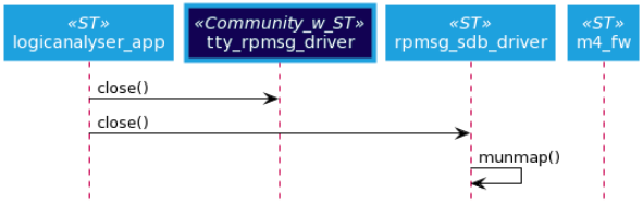
- open/close: get/release file descriptor
  int fd;
  fd= open('/dev/rpmsg_sdb');
  close(fd);
- mmap: allocate and map memories
  void *buff0_id, *buff1_id;

  buff0_id = mmap(NULL, size,  PROT_READ | PROT_WRITE, MAP_PRIVATE, fd, 0);
  buff1_id = mmap(NULL, size,  PROT_READ | PROT_WRITE, MAP_PRIVATE, fd, 0);
- RPMSG_SDB_IOCTL_SET_EFD ioctl: register event for a buffer
  typedef struct
  {
    int bufferId, eventfd;
  } rpmsg_sdb_ioctl_set_efd;

  int efd[NB_BUF];
  rpmsg_sdb_ioctl_set_efd q_set_efd;

  for (i=0;i<NB_BUF;i++){
    /* Create the evenfd, and sent it to kernel driver, for notification of buffer full */
    efd[i] = eventfd(0, 0);

    q_set_efd.bufferId = i;
    q_set_efd.eventfd = efd[i];

    ioctl(mFdSdbRpmsg, RPMSG_SDB_IOCTL_SET_EFD, &q_set_efd)
  }
- RPMSG_SDB_IOCTL_GET_DATA_SIZE ioctl: get the size of a buffer
  typedef struct
  {
    int bufferId;
    uint32_t size;
  } rpmsg_sdb_ioctl_get_data_size;

  rpmsg_sdb_ioctl_get_data_size q_get_data_size;

  q_get_data_size.bufferId = i; // i is the buffer index

  ioctl(fd, RPMSG_SDB_IOCTL_GET_DATA_SIZE, &q_get_data_size);
- Manage event
  while (1) {
    ret = poll(fds, NB_BUF, TIMEOUT * 1000);
    if (ret < 0) {
      perror("poll()");
    } else if (ret) {
      printf("Data is available now.\n");
    } else if (ret == 0) {
      printf("No data within five seconds.\n");
    }
    for (j=0;j<NB_BUF;j++){
      if (fds[j].revents & POLLIN) {
        /* Event received for the buffer j: New data is available for buffer j */
      }
    }
  }
8. Dynamic view[edit | edit source]
At startup, the Linux® application performs the following actions:
- It loads the rpmsg_sdb.ko module.
- It loads the Arm® Cortex®-M firmware, then starts it.
- It opens a rpmsg_tty channel for Arm® Cortex®-M firmware control.
- It opens a rpmsg_tty channel for Arm® Cortex®-M firmware trace debug.
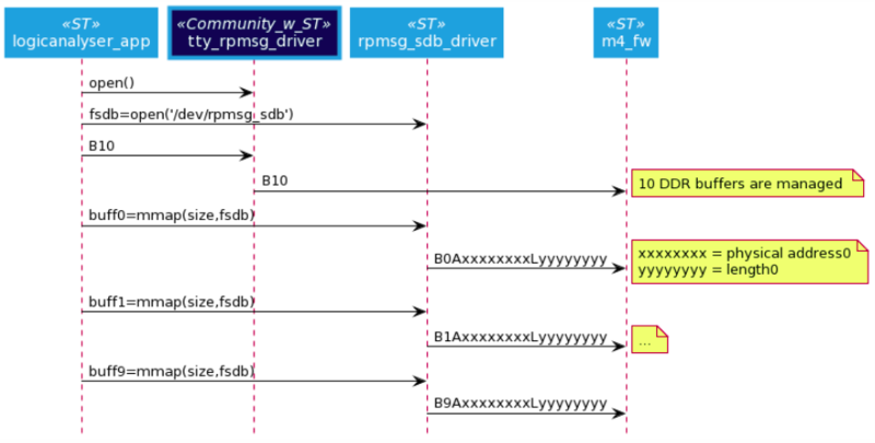
- It opens the rpmsg_sdb driver, then uses rpmsg_sdb IOCTL interface to allocate and mmap 10 buffers of 1 Mbyte in DDR memory.
When the user presses User button2, the Linux® application starts.
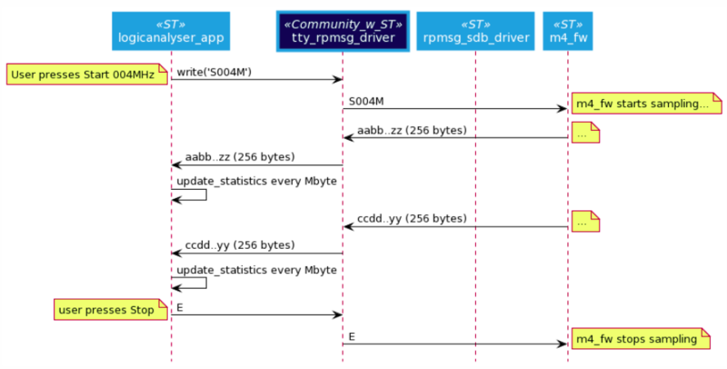
When the START button is pressed, the application sends the sampling command to the Arm® Cortex®-M firmware (including the sampling frequency).
Case 1: user selects a frequency sampling of 2 MHz => case of TTY buffers (low sampling frequency)
- When the Linux® application receives a data buffer over TTY it checks if a new Mbyte has been fully received, and in this case it updates the statistics information.
Case 2: user selects a frequency sampling of 8 MHz => case of copy to DDR buffers (high sampling frequency)
- When the Arm® Cortex®-M firmware sends a "buffer full" signal via the rpmsg_sdb driver, Linux® application updates the statistics information.
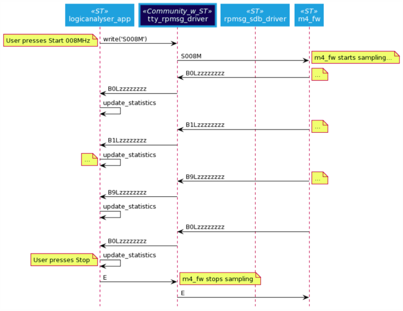
When the STOP button is pressed, the application sends the stop command to the Arm® Cortex®-M firmware.
When the user presses User button2, the Linux® application stops.
Summary of the RPMsg messages exchanged between the processors through the rpmsg_sdb driver:
- Information about the number of shared buffers is sent to the Arm® Cortex®-M. The message is structured in a string with following format: "Bx", where x is the number of shared buffers.
- Information about the buffer allocated and mmaped is sent to the Arm® Cortex®-M.
- The message is structured in a string with following format: "BxAyyyyyyyyLzzzzzzzz", where:
- x: buffer index (32 bits, decimal format, no leading zero)
- yyyyyyyy: physical address of the buffer in DDR (32 bits, 8-digit hexadecimal format, leading zero)
- zzzzzzzz: length of the buffer (32 bits, 8-digit hexadecimal format, leading zero)
- Buffer filled event is received from the Arm® Cortex®-M.
- When the Arm® Cortex®-M4 has filled a buffer, it can inform the Linux® application by sending an RPMsg with following string format: "BxLzzzzzzzz"', where:
- x: buffer index (32 bits, decimal format, no leading zero)
- zzzzzzzz: length of the buffer (32 bits, 8-digit hexadecimal format, leading zero)
In the source code example, 10 buffers of 1 Mbyte each are allocated for the exchange. 3 buffers is the minimum to guarantee the real time behavior of the application. If the number of buffer needs to be increased (more than 10), then the rpmsg_sdb_driver, the M4 firmware, and the Linux® application must be modified, as the messaging relies on a single digit for the buffer index (e.g. "BxLyyyyyyyy" => "BxxLyyyyyyyy").
9. Results[edit | edit source]
The Arm® Cortex®-M CPU performs a mask and copy data operation on 1024 bytes within 75.4 µs; This implies a maximum frequency sampling of: 1 / (75.4e-6 / 1024) => 13.58 MHz. This corresponds to the maximum frequency sampling that can be achieved. In order to let a margin, the maximum frequency sampling implemented in this example is set to 12 MHz.
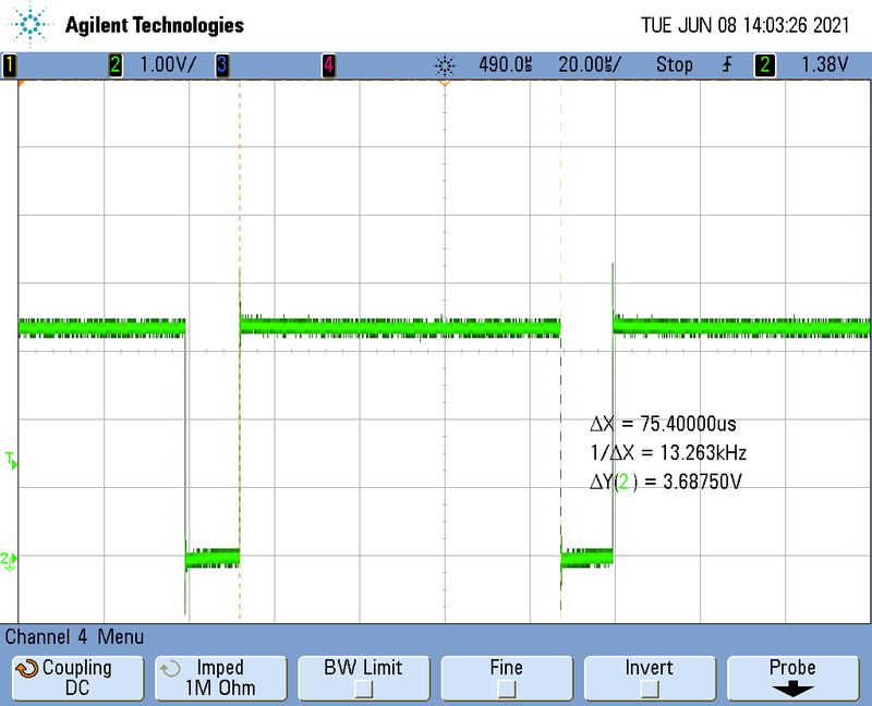
On this oscilloscope snapshot, a GPIO is set at the beginning of the data masking and copying algorithm, and reset at the end of the algorithm. So, 75.4 µs are spent to mask and copy 1024 bytes of data in DDR.
10. Source code[edit | edit source]
The source code corresponding to this use case is available as a Yocto layer at:
- https://github.com/STMicroelectronics/meta-st-stm32mpu-app-logicanalyser.git ("scarthgap" branch for the ecosystem release v6.0.0
 ).
).
The Cortex®-M4 firmware is included in the Yocto layer as an .elf file.
The source code of the Cortex®-M4 firmware is available at:
- https://github.com/STMicroelectronics/logicanalyser ("scarthgap" branch for the ecosystem release v6.0.0 ).
For firmware compilation, please have a look into: Developer Package for STM32CubeMP15.
11. Key messages[edit | edit source]
Arm® Cortex®-M is capable to perform basic algorithm on high data flow. If a more complex data treatment is needed, the data rate must be adapted to be able to treat it on Arm® Cortex®-M.
Code instrumentation and GPIO set/reset to measure data algorithm timing are highly recommended to check real time of the full system.
For a low data rate (i.e., less than or equal to 2 MB/s), TTY over RPMSG should be the preferred solution.
It is not recommended to use several DMA2 streams to deal with high data rates: using a second DMA stream to transfer data to DDR does not work if both streams work at same high rate (trials at 6 MHz proved this); in this case a DMA stream0 error occurs.
12. Usage[edit | edit source]
Please follow README.md of the Yocto layer to perform installation.
The logicanalyser application is launched/stopped by pressing User2 button of the STM32MP1 Discovery board.
Select the sampling frequency and click on Start to start the use case.
Snapshot view of user interface:
If the following log is displayed in the host console, it means that data are lost because the system is not able to process quickly enough the received data (which leads to a shortage of buffers): it might indicate that the indirect buffer exchange mode shall be used instead of the direct buffer exchange mode for this use case.
rpmsg_tty virtio0.rpmsg-tty.-1.1025: Trunc buffer: available space is 0
13. References[edit | edit source]
Arm® is a registered trademark of Arm Limited (or its subsidiaries) in the US and/or elsewhere. ![]()
Arm® is a registered trademark of Arm Limited (or its subsidiaries) in the US and/or elsewhere. ![]()