This article lists all internal peripherals embedded in STM32MP15 device and shows the assignment possibilities to the runtime contexts for each one of them.
Via this article, you can also access to individual peripheral articles in which information related to the overview and configuration can be found.
1. Internal peripherals overview[edit source]
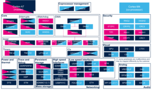
The figure below shows all peripherals embedded in STM32MP15 device, grouped per functional domains that are reused in many places of this wiki to structure the articles.
Several runtime contexts exist on STM32MP15 device[1], corresponding to the different Arm cores and associated security modes:
- Arm dual core Cortex-A7 secure (Trustzone), running a Secure Monitor or Secure OS like OP-TEE
- Arm dual core Cortex-A7 non secure , running Linux
- Arm Cortex-M4 (non-secure), running STM32Cube
Some peripherals can be strictly assigned to one runtime context: this is the case for most of the peripherals, like USART or I2C.
Other ones can be shared between several runtime contexts: this is the case for system peripherals, like PWR or RCC.
The legend below shows how assigned and shared peripherals are identified in the assignment diagram that follows:

Both the diagram below and the following summary table (in Internal peripherals assignment chapter below) are clickable in order to jump to each peripheral overview articles and get more detailed information (like software frameworks used to control them). They list STMicroelectronics recommendations. The STM32MP15 reference manual [2] may expose more possibilities than what is shown here.

2. Internal peripherals assignment[edit source]
Click on the right to expand the legend...
Check boxes illustrate the possible peripheral allocations supported by STM32 MPU Embedded Software:
- ☐ means that the peripheral can be assigned (☑) to the given runtime context.
- ⬚ means that the peripheral can be assigned to the given runtime context, but this configuration is not supported in STM32 MPU Embedded Software distribution.
- ✓ is used for system peripherals that cannot be unchecked because they are statically connected in the device.
Refer to How to assign an internal peripheral to an execution context for more information on how to assign peripherals manually or via STM32CubeMX.
The present chapter describes STMicroelectronics recommendations or choice of implementation. Additional possiblities might be described in STM32MP15 reference manuals.
3. Article purpose[edit source]
The purpose of this article is to:
- briefly introduce the ADC peripheral and its main features,
- indicate the peripheral instances assignment at boot time and their assignment at runtime (including whether instances can be allocated to secure contexts),
- list the software frameworks and drivers managing the peripheral,
- explain how to configure the peripheral.
4. Peripheral overview[edit source]
The ADC peripheral is a successive approximation analog-to-digital converter.
The STM32MP15 has one ADC block with two physical ADCs:
- Configurable resolution: 8, 10, 12, 14, 16 bits.
- Each ADC has up to 20 multiplexed channels (including 6 internal channels connected only to ADC2).
- The conversions can be performed in single, continuous, scan or discontinuous mode.
- The result can be read in a left- or right-aligned 32-bit data register by using CPU or DMA[3].
- The analog watchdog feature allows the application to detect if the input voltage goes beyond the user-defined, high or low thresholds.
- A common input clock for the two ADCs, which can be selected between 2 different clock[4] sources (Synchronous or Asynchronous clock).
- The common reference voltage can be provided by either VREFBUF[5] or any other external regulator[6] wired to VREF+ pin.
Each ADC supports two contexts to manage conversions:
- Regular conversions can be done in sequence, running in background
- Injected conversions have higher priority, and so have the ability to interrupt the regular sequence (either triggered in SW or HW). The regular sequence is resumed, in case it has been interrupted.
- Each context has its own configurable sequence and trigger: software, TIM[7], LPTIM[8] and EXTI[9].
Refer to the STM32MP15 reference manuals for the complete list of features, and to the software frameworks and drivers, introduced below, to see which features are implemented.
5. Peripheral usage[edit source]
This chapter is applicable in the scope of the OpenSTLinux BSP running on the Arm® Cortex®-A processor(s), and the STM32CubeMPU Package running on the Arm® Cortex®-M processor.
5.1. Boot time assignment[edit source]
5.1.1. On STM32MP15x lines  [edit source]
The ADC is usually not used at boot time. But it may be used by the SSBL (see Boot chain overview), to check for power supplies for example.
Click on ![]() to expand or collapse the legend...
to expand or collapse the legend...
Check boxes illustrate the possible peripheral allocations supported by STM32 MPU Embedded Software:
- ☐ means that the peripheral can be assigned to the given boot time context.
- ☑ means that the peripheral is assigned by default to the given boot time context and that the peripheral is mandatory for the STM32 MPU Embedded Software distribution.
- ⬚ means that the peripheral can be assigned to the given boot time context, but this configuration is not supported in STM32 MPU Embedded Software distribution.
- ✓ is used for system peripherals that cannot be unchecked because they are hardware connected in the device.
The present chapter describes STMicroelectronics recommendations or choice of implementation. Additional possibilities might be described in STM32 MPU reference manuals.
| Domain | Peripheral | Runtime allocation | Comment | |||
|---|---|---|---|---|---|---|
| Instance | Cortex-A7 secure (OP-TEE) |
Cortex-A7 non-secure (Linux) |
Cortex-M4 (STM32Cube) | |||
| Domain | Peripheral | Boot time allocation | Comment | |||
|---|---|---|---|---|---|---|
| Instance | Cortex-A7 secure (ROM code) |
Cortex-A7 secure (TF-A BL2) |
Cortex-A7 non-secure (U-Boot) | |||
| Analog | ADC | ADC | ☐ | |||
5.2. Runtime assignment[edit source]
5.2.1. On STM32MP15x lines [edit source]
Click on ![]() to expand or collapse the legend...
to expand or collapse the legend...
Check boxes illustrate the possible peripheral allocations supported by STM32 MPU Embedded Software:
- ☐ means that the peripheral can be assigned to the given runtime context.
- ☑ means that the peripheral is assigned by default to the given runtime context and that the peripheral is mandatory for the STM32 MPU Embedded Software distribution.
- ⬚ means that the peripheral can be assigned to the given runtime context, but this configuration is not supported in STM32 MPU Embedded Software distribution.
- ✓ is used for system peripherals that cannot be unchecked because they are hardware connected in the device.
Refer to How to assign an internal peripheral to an execution context for more information on how to assign peripherals manually or via STM32CubeMX.
The present chapter describes STMicroelectronics recommendations or choice of implementation. Additional possiblities might be described in STM32MP15 reference manuals.
| Domain | Peripheral | Runtime allocation | Comment | |||
|---|---|---|---|---|---|---|
| Instance | Cortex-A7 secure (OP-TEE) |
Cortex-A7 non-secure (Linux) |
Cortex-M4 (STM32Cube) | |||
| Analog | ADC | ADC | ☐ | ☐ | Assignment (single choice) | |
6. Software frameworks and drivers[edit source]
Below are listed the software frameworks and drivers managing the ADC peripheral for the embedded software components listed in the above tables.
- Linux®: IIO framework
- STM32Cube: HAL ADC driver
- U-Boot: U-Boot ADC driver
7. How to assign and configure the peripheral[edit source]
The peripheral assignment can be done via the STM32CubeMX graphical tool (and manually completed if needed).
This tool also helps to configure the peripheral:
- partial device trees (pin control and clock tree) generation for the OpenSTLinux software components,
- HAL initialization code generation for the STM32CubeMPU Package.
The configuration is applied by the firmware running in the context in which the peripheral is assigned.
For the Linux kernel and U-boot configuration, please refer to ADC device tree configuration article.
8. How to go further[edit source]
See application notes:
- How to get the best ADC accuracy in STM32[10].
- Getting started with STM32MP15 series hardware development (AN5031)[11].
It deals with analog domain power supply and reference voltage.
9. References[edit source]
- ↑ Category:STM32_MPU_microprocessor_devices#Multiple-core_architecture_concepts
- ↑ STM32MP15 reference manuals
- ↑ DMA internal peripheral
- ↑ RCC internal peripheral
- ↑ VREFBUF internal peripheral
- ↑ Regulator overview
- ↑ TIM internal peripheral
- ↑ LPTIM internal peripheral
- ↑ EXTI internal peripheral
- ↑ How to get the best ADC accuracy in STM32, by STMicroelectronics
- ↑ Getting started with STM32MP15 series hardware development, by STMicroelectronics
10. Article purpose[edit source]
The purpose of this article is to:
- briefly introduce the DAC peripheral and its main features,
- indicate the peripheral instances assignment at boot time and their assignment at runtime (including whether instances can be allocated to secure contexts),
- list the software frameworks and drivers managing the peripheral,
- explain how to configure the peripheral.
11. Peripheral overview[edit source]
The DAC peripheral is a voltage output digital-to-analog converter:
- It may be configured in 8- or 12-bit mode (data could be left- or right-aligned)
- It has two output channels, each with its own converter
- The dual DAC channel mode could be done independently or simultaneously
- It has built-in noise and triangle waveform generator and supports triggers for conversions, using: TIM[1], LPTIM[2] or EXTI[3]
- The DAC output buffer allows a high drive output current
- It can operate under Normal mode or low-power Sample and Hold mode (uses LSI clock, from RCC[4]).
- It may be used in conjunction with the DMA[5] controller (with underrun error detection)
- The common reference voltage, can be provided by either VREFBUF[6] or any other external regulator[7] wired to VREF+ pin.
Refer to the STM32MP15 reference manuals for the complete list of features, and to the software frameworks and drivers, introduced below, to see which features are implemented.
12. Peripheral usage[edit source]
This chapter is applicable in the scope of the OpenSTLinux BSP running on the Arm® Cortex®-A processor(s), and the STM32CubeMPU Package running on the Arm® Cortex®-M processor.
12.1. Boot time assignment[edit source]
The DAC peripheral is not used at boot time.
12.2. Runtime assignment[edit source]
12.2.1. On STM32MP15x lines [edit source]
Click on ![]() to expand or collapse the legend...
to expand or collapse the legend...
Check boxes illustrate the possible peripheral allocations supported by STM32 MPU Embedded Software:
- ☐ means that the peripheral can be assigned to the given runtime context.
- ☑ means that the peripheral is assigned by default to the given runtime context and that the peripheral is mandatory for the STM32 MPU Embedded Software distribution.
- ⬚ means that the peripheral can be assigned to the given runtime context, but this configuration is not supported in STM32 MPU Embedded Software distribution.
- ✓ is used for system peripherals that cannot be unchecked because they are hardware connected in the device.
Refer to How to assign an internal peripheral to an execution context for more information on how to assign peripherals manually or via STM32CubeMX.
The present chapter describes STMicroelectronics recommendations or choice of implementation. Additional possiblities might be described in STM32MP15 reference manuals.
| Domain | Peripheral | Runtime allocation | Comment | |||
|---|---|---|---|---|---|---|
| Instance | Cortex-A7 secure (OP-TEE) |
Cortex-A7 non-secure (Linux) |
Cortex-M4 (STM32Cube) | |||
| Analog | DAC | DAC | ☐ | ☐ | Assignment (single choice) | |
13. Software frameworks and drivers[edit source]
Below are listed the software frameworks and drivers managing the DAC peripheral for the embedded software components listed in the above tables.
- Linux®: IIO framework
- STM32Cube: HAL DAC driver
14. How to assign and configure the peripheral[edit source]
The peripheral assignment can be done via the STM32CubeMX graphical tool (and manually completed if needed).
This tool also helps to configure the peripheral:
- partial device trees (pin control and clock tree) generation for the OpenSTLinux software components,
- HAL initialization code generation for the STM32CubeMPU Package.
The configuration is applied by the firmware running in the context in which the peripheral is assigned.
For the Linux kernel configuration, please refer to DAC device tree configuration and DAC Linux driver articles.
15. References[edit source]
16. Article purpose[edit source]
The purpose of this article is to:
- briefly introduce the VREFBUF peripheral and its main features,
- indicate the peripheral instances assignment at boot time and their assignment at runtime (including whether instances can be allocated to secure contexts),
- list the software frameworks and drivers managing the peripheral,
- explain how to configure the peripheral.
17. Peripheral overview[edit source]
The VREFBUF peripheral is an internal voltage regulator.
The VREFBUF is supplied via the VDDA pin. When enabled, it can provide a reference voltage in the range of: 1,5V, 1,8V, 2,048V or 2,5V.
The VREFBUF can be used to provide an analog voltage reference for:
- ADC internal peripheral
- DAC internal peripheral
- External components through the dedicated VREF+ pin.
The VREFBUF can be left unused. In this case, an external voltage regulator can provide reference voltage to VREF+ pin.
Refer to the STM32MP15 reference manuals for the complete list of features, and to the software frameworks and drivers, introduced below, to see which features are implemented.
18. Peripheral usage[edit source]
This chapter is applicable in the scope of the OpenSTLinux BSP running on the Arm® Cortex®-A processor(s), and the STM32CubeMPU Package running on the Arm® Cortex®-M processor.
18.1. Boot time assignment[edit source]
18.1.1. On STM32MP15x lines [edit source]
The VREFBUF is not used at boot time.
18.2. Runtime assignment[edit source]
18.2.1. On STM32MP15x lines [edit source]
Click on ![]() to expand or collapse the legend...
to expand or collapse the legend...
Check boxes illustrate the possible peripheral allocations supported by STM32 MPU Embedded Software:
- ☐ means that the peripheral can be assigned to the given runtime context.
- ☑ means that the peripheral is assigned by default to the given runtime context and that the peripheral is mandatory for the STM32 MPU Embedded Software distribution.
- ⬚ means that the peripheral can be assigned to the given runtime context, but this configuration is not supported in STM32 MPU Embedded Software distribution.
- ✓ is used for system peripherals that cannot be unchecked because they are hardware connected in the device.
Refer to How to assign an internal peripheral to an execution context for more information on how to assign peripherals manually or via STM32CubeMX.
The present chapter describes STMicroelectronics recommendations or choice of implementation. Additional possiblities might be described in STM32MP15 reference manuals.
| Domain | Peripheral | Runtime allocation | Comment | |||
|---|---|---|---|---|---|---|
| Instance | Cortex-A7 secure (OP-TEE) |
Cortex-A7 non-secure (Linux) |
Cortex-M4 (STM32Cube) | |||
| Analog | VREFBUF | VREFBUF | ☐ | ☐ | Assignment (single choice) | |
19. Software frameworks and drivers[edit source]
Below are listed the software frameworks and drivers managing the VREFBUF peripheral for the embedded software components listed in the above tables.
- Linux®: regulator framework
20. How to assign and configure the peripheral[edit source]
The peripheral assignment can be done via the STM32CubeMX graphical tool (and manually completed if needed).
This tool also helps to configure the peripheral:
- partial device trees (pin control and clock tree) generation for the OpenSTLinux software components,
- HAL initialization code generation for the STM32CubeMPU Package.
The configuration is applied by the firmware running in the context in which the peripheral is assigned.
- For the Linux kernel configuration, please refer to device internal regulator. An example can be found also in ADC DT configuration examples
- In case the control of VREFBUF consumers are spread across the various cores, see also Resource manager for coprocessing
21. References[edit source]
- ↑ 1.0 1.1 Resource manager for coprocessing, focus on system resources
22. Article purpose[edit source]
The purpose of this article is to:
- briefly introduce the IPCC peripheral and its main features,
- indicate the peripheral instances assignment at boot time and their assignment at runtime (including whether instances can be allocated to secure contexts),
- list the software frameworks and drivers managing the peripheral,
- explain how to configure the peripheral.
23. Peripheral overview[edit source]
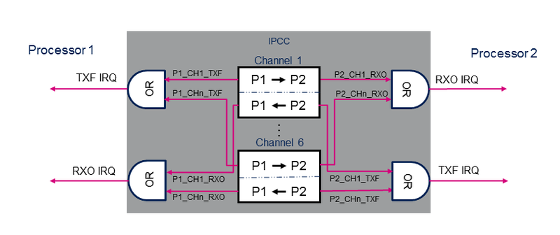
The IPCC (inter-processor communication controller) peripheral is used to exchange data between two processors. It provides a non blocking signaling mechanism to post and retrieve information in an atomic way. Note that shared memory buffers are allocated in the MCU SRAM, which is not part of the IPCC block.
The IPCC peripheral provides a hardware support to manage inter-processor communication between two processor instances. Each processor owns specific register bank and interrupts.
The IPCC provides the signaling for six bidirectional channels.
Each channel is divided into two subchannels that offer a unidirectional signaling from the "sender" processor to the "receiver" processor:
- P1_TO_P2 subchannel
- P2_TO_P1 subchannel
A subchannel consists in:
- One flag that toggles between occupied and free: the flag is set to occupied by the "sender" processor and cleared by the "receiver" processor.
- Two associated interrupts (shared with the other channels):
- RXO: RX channel occupied, connected to the "receiver" processor.
- TXF: TX channel free, connected to the "sender" processor.
- Two associated interrupt masks multiplexing channel IRQs.
The IPCC supports the following channel operating modes:
- Simplex communication mode:
- Only one subchannel is used.
- Unidirectional messages: once the "sender" processor has posted the communication data in the memory, it sets the channel status flag to occupied. The "receiver" processor clears the flag when the message is treated.
- Half-duplex communication mode:
- Only one subchannel is used.
- Bidirectional messages: once the "sender" processor has posted the communication data in the memory, it sets the channel status flag to occupied. The "receiver" processor clears the flag when the message is treated and the response is available in shared memory.
- Full-duplex communication mode:
- The subchannels are used in Asynchronous mode.
- Any processor can post asynchronously a message by setting the subchannel status flag to occupied. The "receiver" processor clears the flag when the message is treated. This mode can be considered as a combination of two simplex modes on a given channel.
Refer to the reference manuals[1][2] for the complete list of features, and to the software frameworks and drivers, introduced below, to see which features are implemented.
24. Peripheral usage[edit source]
This chapter is applicable in the scope of the OpenSTLinux BSP running on the Arm® Cortex®-A processor(s), and the STM32CubeMPU Package running on the Arm® Cortex®-M processor.
24.1. Processor interface assignment[edit source]
24.1.1. On STM32MP15x lines [edit source]
STMicroelectronics distribution uses the IPCC peripheral for inter-processor communication with the following configuration:
- The IPCC processor 1 interface (PROC1)is assigned to the Arm® Cortex®-A7, non-secure context.
- The IPCC processor 2 interface (PROC2) is assigned to the Arm® Cortex®-M4 context.
24.1.2. On STM32MP25x lines [edit source]
- The IPCC1 peripheral is dedicated for the communication between the Arm® Cortex®-A35 and the Arm® Cortex®-M33. The interfaces are assigned in hardware to the Cortexes :
- The processor 1 interface (PROC1) is assigned by hardware to the Arm® Cortex®-A35, secure and non-secure context.
- The processor 2 interface (PROC2) is assigned by hardware to the Arm® Cortex®-M33, secure and non-secure context.
- The IPCC2 peripheral is dedicated for the communication between the Arm® Cortex®-A35 or the Arm® Cortex®-M33 and the Arm® Cortex®-M0+.
- The processor 1 interface (PROC1) is assigned by hardware to the Arm® Cortex®-M0+.
- The processor 2 interface (PROC2) is assignable to the Arm® Cortex®-A35 or the Arm® Cortex®-M33, secure and non-secure context.
24.2. Boot time assignment[edit source]
24.2.1. On STM32MP15x lines [edit source]
The IPCC peripheral is not used at boot time.
24.2.2. On STM32MP25x lines [edit source]
Click on ![]() to expand or collapse the legend...
to expand or collapse the legend...
- ☐ means that the peripheral can be assigned to the given boot time context.
- ☑ means that the peripheral is assigned by default to the given boot time context and that the peripheral is mandatory for the STM32 MPU Embedded Software distribution.
- ⬚ means that the peripheral can be assigned to the given boot time context, but this configuration is not supported in STM32 MPU Embedded Software distribution.
- ✓ is used for system peripherals that cannot be unchecked because they are hardware connected in the device.
The present chapter describes STMicroelectronics recommendations or choice of implementation. Additional possibilities might be described in STM32MP25 reference manuals.
| Domain | Peripheral | Boot time allocation | Comment | |||
|---|---|---|---|---|---|---|
| Instance | Cortex-A35 secure (ROM code) |
Cortex-A35 secure (TF-A BL2) |
Cortex-A35 non-secure (U-Boot) | |||
| Coprocessor | IPCC |
IPCC1 | ⬚ | ⬚ | Shareable at internal peripheral level thanks to the RIF: see the boot time allocation per feature | |
| IPCC2 | ⬚ | ⬚ | Shareable at internal peripheral level thanks to the RIF: see the boot time allocation per feature | |||
The below table shows the possible boot time allocations for the features of the IPCC1 instance.
| Feature | Boot time allocation |
Comment | ||
|---|---|---|---|---|
| Cortex-A35 secure (ROM code) |
Cortex-A35 secure (TF-A BL2) |
Cortex-A35 non-secure (U-Boot) | ||
| PROC1 channel 1 | ⬚ | ⬚ | ||
| PROC1 channel 2 | ⬚ | ⬚ | ||
| PROC1 channel 3 | ⬚ | ⬚ | ||
| PROC1 channel 4 | ⬚ | ⬚ | ||
| PROC1 channel 5 | ⬚ | ⬚ | ||
| PROC1 channel 6 | ⬚ | ⬚ | ||
| PROC1 channel 7 | ⬚ | ⬚ | ||
| PROC1 channel 8 | ⬚ | ⬚ | ||
| PROC1 channel 9 | ⬚ | ⬚ | ||
| PROC1 channel 10 | ⬚ | ⬚ | ||
| PROC1 channel 11 | ⬚ | ⬚ | ||
| PROC1 channel 12 | ⬚ | ⬚ | ||
| PROC1 channel 13 | ⬚ | ⬚ | ||
| PROC1 channel 14 | ⬚ | ⬚ | ||
| PROC1 channel 15 | ⬚ | ⬚ | ||
| PROC1 channel 16 | ⬚ | ⬚ | ||
| PROC2 channel 1 | ||||
| PROC2 channel 2 | ||||
| PROC2 channel 3 | ||||
| PROC2 channel 4 | ||||
| PROC2 channel 5 | ||||
| PROC2 channel 6 | ||||
| PROC2 channel 7 | ||||
| PROC2 channel 8 | ||||
| PROC2 channel 9 | ||||
| PROC2 channel 10 | ||||
| PROC2 channel 11 | ||||
| PROC2 channel 12 | ||||
| PROC2 channel 13 | ||||
| PROC2 channel 14 | ||||
| PROC2 channel 15 | ||||
| PROC2 channel 16 | ||||
The below table shows the possible boot time allocations for the features of the IPCC2 instance.
| Feature | Boot time allocation |
Comment | ||
|---|---|---|---|---|
| Cortex-A35 secure (ROM code) |
Cortex-A35 secure (TF-A BL2) |
Cortex-A35 non-secure (U-Boot) | ||
| PROC1 channel 1 | ||||
| PROC1 channel 2 | ||||
| PROC1 channel 3 | ||||
| PROC1 channel 4 | ||||
| PROC2 channel 1 | ⬚ | ⬚ | ||
| PROC2 channel 2 | ⬚ | ⬚ | ||
| PROC2 channel 3 | ⬚ | ⬚ | ||
| PROC2 channel 4 | ⬚ | ⬚ | ||
24.3. Runtime assignment[edit source]
It does not make sense to allocate the IPCC to a single runtime execution context. It is consequently enabled by default for both cores in the STM32CubeMX.
24.3.1. On STM32MP15x lines [edit source]
Click on ![]() to expand or collapse the legend...
to expand or collapse the legend...
Check boxes illustrate the possible peripheral allocations supported by STM32 MPU Embedded Software:
- ☐ means that the peripheral can be assigned to the given runtime context.
- ☑ means that the peripheral is assigned by default to the given runtime context and that the peripheral is mandatory for the STM32 MPU Embedded Software distribution.
- ⬚ means that the peripheral can be assigned to the given runtime context, but this configuration is not supported in STM32 MPU Embedded Software distribution.
- ✓ is used for system peripherals that cannot be unchecked because they are hardware connected in the device.
Refer to How to assign an internal peripheral to an execution context for more information on how to assign peripherals manually or via STM32CubeMX.
The present chapter describes STMicroelectronics recommendations or choice of implementation. Additional possiblities might be described in STM32MP15 reference manuals.
| Domain | Peripheral | Runtime allocation | Comment | |||
|---|---|---|---|---|---|---|
| Instance | Cortex-A7 secure (OP-TEE) |
Cortex-A7 non-secure (Linux) |
Cortex-M4 (STM32Cube) | |||
| Coprocessor | IPCC | IPCC | ☑ | ☑ | Shared (none or both) | |
| Processor interface | Context | Comment | ||
|---|---|---|---|---|
| Cortex-A7 non-secure (Linux) |
Cortex-M4 (STM32Cube) | |||
| PROC1 channel 1 | ☑ | RPMsg transfer from Cortex-M to Cortex-A
Full-duplex communication:
| ||
| PROC1 channel 2 | ☑ | RPMsg transfer from Cortex-A to Cortex-M
Full-duplex communication:
| ||
| PROC1 channel 3 | ☑ | Simplex communication used by the remote framework to request the Cortex-M4 to shutdown. | ||
| PROC1 channel 4 | ☐ | |||
| PROC1 channel 5 | ☐ | |||
| PROC1 channel 6 | ☐ | |||
| PROC2 channel 1 | ☑ | RPMsg transfer from Cortex-M to Cortex-A
Full-duplex communication:
| ||
| PROC2 channel 2 | ☑ | RPMsg transfer from Cortex-A to Cortex-M
Full-duplex communication:
| ||
| PROC2 channel 3 | ☑ | Simplex communication used by the remote framework to request the Cortex-M4 to shutdown. | ||
| PROC2 channel 4 | ☐ | |||
| PROC2 channel 5 | ☐ | |||
| PROC2 channel 6 | ☐ | |||
24.3.2. On STM32MP25x lines [edit source]
Click on ![]() to expand or collapse the legend...
to expand or collapse the legend...
Check boxes illustrate the possible peripheral allocations supported by STM32 MPU Embedded Software:
- ☐ means that the peripheral can be assigned to the given runtime context.
- ☑ means that the peripheral is assigned by default to the given runtime context and that the peripheral is mandatory for the STM32 MPU Embedded Software distribution.
- ⬚ means that the peripheral can be assigned to the given runtime context, but this configuration is not supported in STM32 MPU Embedded Software distribution.
- ✓ is used for system peripherals that cannot be unchecked because they are hardware connected in the device.
The present chapter describes STMicroelectronics recommendations or choice of implementation. Additional possibilities might be described in STM32MP25 reference manuals.
| Domain | Peripheral | Runtime allocation | Comment | |||||
|---|---|---|---|---|---|---|---|---|
| Instance | Cortex-A35 secure (OP-TEE / TF-A BL31) |
Cortex-A35 non-secure (Linux) |
Cortex-M33 secure (TF-M) |
Cortex-M33 non-secure (STM32Cube) |
Cortex-M0+ (STM32Cube) | |||
| Coprocessor | IPCC |
IPCC1 | ☐OP-TEE | ☐ | ☐ | ☐ | Shareable at internal peripheral level thanks to the RIF: see the runtime allocation per feature | |
| IPCC2 | ☐OP-TEE | ☐ | ☐ | ☐ | ☐ | Shareable at internal peripheral level thanks to the RIF: see the runtime allocation per feature | ||
The below table shows the possible runtime allocations for the features of the IPCC1 instance.
| Feature | Runtime allocation |
Comment | ||||
|---|---|---|---|---|---|---|
| Cortex-A35 secure (OP-TEE / TF-A BL31) |
Cortex-A35 non-secure (Linux) |
Cortex-M33 secure (TF-M) |
Cortex-M33 non-secure (STM32Cube) |
Cortex-M0+ (STM32Cube) | ||
| PROC1 channel 1 | ☐OP-TEE | ☑ | RPMsg transfer from Cortex-M to Cortex-A
Full-duplex communication:
| |||
| PROC1 channel 2 | ☐OP-TEE | ☑ | RPMsg transfer from Cortex-A to Cortex-M
Full-duplex communication:
| |||
| PROC1 channel 3 | ☐OP-TEE | ☑ | Simplex communication used by the remoteproc framework to request the Cortex-M33 to shutdown. | |||
| PROC1 channel 4 | ☐OP-TEE | ☐ | ||||
| PROC1 channel 5 | ☐OP-TEE | ☐ | ||||
| PROC1 channel 6 | ☐OP-TEE | ☐ | ||||
| PROC1 channel 7 | ☐OP-TEE | ☐ | ||||
| PROC1 channel 8 | ☐OP-TEE | ☐ | ||||
| PROC1 channel 9 | ☐OP-TEE | ☐ | ||||
| PROC1 channel 10 | ☐OP-TEE | ☐ | ||||
| PROC1 channel 11 | ☐OP-TEE | ☐ | ||||
| PROC1 channel 12 | ☐OP-TEE | ☐ | ||||
| PROC1 channel 13 | ☐OP-TEE | ☐ | Allocated to secure world but not used. | |||
| PROC1 channel 14 | ☐OP-TEE | ☐ | Allocated to secure world but not used. | |||
| PROC1 channel 15 | ☐OP-TEE | ☐ | Allocated to secure world but not used. | |||
| PROC1 channel 16 | ☐OP-TEE | ☐ | Allocated to secure world but not used. | |||
| PROC2 channel 1 | ☐ | ☑ | RPMsg transfer from Cortex-M to Cortex-A
Full-duplex communication:
| |||
| PROC2 channel 2 | ☐ | ☑ | RPMsg transfer from Cortex-A to Cortex-M
Full-duplex communication:
| |||
| PROC2 channel 3 | ☐ | ☑ | Simplex communication used by the remoteproc framework to request the Cortex-M33 to shutdown. | |||
| PROC2 channel 4 | ☐ | ☐ | ||||
| PROC2 channel 5 | ☐ | ☐ | ||||
| PROC2 channel 6 | ☐ | ☐ | ||||
| PROC2 channel 7 | ☐ | ☐ | ||||
| PROC2 channel 8 | ☐ | ☐ | ||||
| PROC2 channel 9 | ☐ | ☐ | ||||
| PROC2 channel 10 | ☐ | ☐ | ||||
| PROC2 channel 11 | ☐ | ☐ | ||||
| PROC2 channel 12 | ☐ | ☐ | ||||
| PROC2 channel 13 | ☐ | ☐ | ||||
| PROC2 channel 14 | ☐ | ☐ | ||||
| PROC2 channel 15 | ☐ | ☐ | ||||
| PROC2 channel 16 | ☐ | ☐ | ||||
The below table shows the possible runtime allocations for the features of the IPCC2 instance.
| Feature | Runtime allocation |
Comment | ||||
|---|---|---|---|---|---|---|
| Cortex-A35 secure (OP-TEE / TF-A BL31) |
Cortex-A35 non-secure (Linux) |
Cortex-M33 secure (TF-M) |
Cortex-M33 non-secure (STM32Cube) |
Cortex-M0+ (STM32Cube) | ||
| PROC1 channel 1 | ☐ | |||||
| PROC1 channel 2 | ☐ | |||||
| PROC1 channel 3 | ☐ | |||||
| PROC1 channel 4 | ☐ | |||||
| PROC2 channel 1 | ☐OP-TEE | ☐ | ☐ | ☐ | ||
| PROC2 channel 2 | ☐OP-TEE | ☐ | ☐ | ☐ | ||
| PROC2 channel 3 | ☐OP-TEE | ☐ | ☐ | ☐ | ||
| PROC2 channel 4 | ☐OP-TEE | ☐ | ☐ | ☐ | ||
25. Software frameworks and drivers[edit source]
Below are listed the software frameworks and drivers managing the IPCC peripheral for the embedded software components listed in the above tables.
- Linux®: mailbox framework
- STM32Cube: IPCC HAL driver and header file of IPCC HAL module
26. How to assign and configure the peripheral[edit source]
The peripheral assignment can be done via the STM32CubeMX graphical tool (and manually completed if needed).
This tool also helps to configure the peripheral:
- partial device trees (pin control and clock tree) generation for the OpenSTLinux software components,
- HAL initialization code generation for the STM32CubeMPU Package.
The configuration is applied by the firmware running in the context in which the peripheral is assigned.The IPCC peripheral is shared between the Arm Cortex-A and Cortex-M contexts. A particular attention must therefore be paid to have a complementary configuration on both contexts.
27. Article purpose[edit source]
The purpose of this article is to:
- briefly introduce the HSEM peripheral and its main features,
- indicate the peripheral instances assignment at boot time and their assignment at runtime (including whether instances can be allocated to secure contexts),
- list the software frameworks and drivers managing the peripheral,
- explain how to configure the peripheral.
28. Peripheral overview[edit source]
The HSEM (hardware spinlock) peripheral is used to provide synchronization and mutual exclusion between heterogeneous processors.
- 32 hardware semaphores are available on the platform.
- semaphores could be accessed by the Arm® Cortex®-A7 core and the Arm® Cortex®-M4
Refer to the STM32MP15 reference manuals for the complete list of features, and to the software frameworks and drivers, introduced below, to see which features are implemented.
29. Peripheral usage[edit source]
This chapter is applicable in the scope of the OpenSTLinux BSP running on the Arm® Cortex®-A processor(s), and the STM32CubeMPU Package running on the Arm® Cortex®-M processor.
29.1. Boot time assignment[edit source]
29.1.1. On STM32MP15x lines [edit source]
The hardware semaphore is used at boot time for GPIO access protection between the Arm® Cortex®-A7 and Cortex®-M4 cores. See Protecting GPIO and EXTI system resources by hardware semaphores for details.
Click on ![]() to expand or collapse the legend...
to expand or collapse the legend...
Check boxes illustrate the possible peripheral allocations supported by STM32 MPU Embedded Software:
- ☐ means that the peripheral can be assigned to the given boot time context.
- ☑ means that the peripheral is assigned by default to the given boot time context and that the peripheral is mandatory for the STM32 MPU Embedded Software distribution.
- ⬚ means that the peripheral can be assigned to the given boot time context, but this configuration is not supported in STM32 MPU Embedded Software distribution.
- ✓ is used for system peripherals that cannot be unchecked because they are hardware connected in the device.
The present chapter describes STMicroelectronics recommendations or choice of implementation. Additional possibilities might be described in STM32 MPU reference manuals.
| Domain | Peripheral | Boot time allocation | Comment | |||
|---|---|---|---|---|---|---|
| Instance | Cortex-A7 secure (ROM code) |
Cortex-A7 secure (TF-A BL2) |
Cortex-A7 non-secure (U-Boot) | |||
| Coprocessor | HSEM | HSEM | ☐ | |||
29.2. Runtime assignment[edit source]
29.2.1. On STM32MP15x lines [edit source]
It does not make sense to allocate HSEM to a single runtime execution context, that is why it is enabled by default for both cores in the STM32CubeMX.
The hardware semaphore is used at runtime for GPIO and EXTI access protection between the Arm® Cortex®-A7 and Cortex®-M4 cores. See Protecting GPIO and EXTI system resources by hardware semaphores for details.
Click on ![]() to expand or collapse the legend...
to expand or collapse the legend...
Check boxes illustrate the possible peripheral allocations supported by STM32 MPU Embedded Software:
- ☐ means that the peripheral can be assigned to the given runtime context.
- ☑ means that the peripheral is assigned by default to the given runtime context and that the peripheral is mandatory for the STM32 MPU Embedded Software distribution.
- ⬚ means that the peripheral can be assigned to the given runtime context, but this configuration is not supported in STM32 MPU Embedded Software distribution.
- ✓ is used for system peripherals that cannot be unchecked because they are hardware connected in the device.
Refer to How to assign an internal peripheral to an execution context for more information on how to assign peripherals manually or via STM32CubeMX.
The present chapter describes STMicroelectronics recommendations or choice of implementation. Additional possiblities might be described in STM32MP15 reference manuals.
| Domain | Peripheral | Runtime allocation | Comment | |||
|---|---|---|---|---|---|---|
| Instance | Cortex-A7 secure (OP-TEE) |
Cortex-A7 non-secure (Linux) |
Cortex-M4 (STM32Cube) | |||
| Coprocessor | HSEM | HSEM | ⬚ | ☑ | ☑ | |
30. Software frameworks and drivers[edit source]
Below are listed the software frameworks and drivers managing the HSEM peripheral for the embedded software components listed in the above tables.
- Linux®: hardware spinlock framework
- STM32Cube: HSEM HAL driver and header file of HSEM HAL module
31. How to assign and configure the peripheral[edit source]
The peripheral assignment can be done via the STM32CubeMX graphical tool (and manually completed if needed).
This tool also helps to configure the peripheral:
- partial device trees (pin control and clock tree) generation for the OpenSTLinux software components,
- HAL initialization code generation for the STM32CubeMPU Package.
The configuration is applied by the firmware running in the context in which the peripheral is assigned.
The HSEM peripheral is shared between the Cortex-A and Cortex-M contexts, so a particular attention must be paid to have a complementary configuration on both contexts.
STM32MP15 RTC internal peripheral
STM32MP15 SYSCFG internal peripheral
32. Article purpose[edit source]
The purpose of this article is to:
- briefly introduce the NVIC peripheral and its main features,
- indicate the peripheral instances assignment at boot time and their assignment at runtime (including whether instances can be allocated to secure contexts),
- list the software frameworks and drivers managing the peripheral,
- explain how to configure the peripheral.
33. Peripheral overview[edit source]
The NVIC peripheral is the Arm® Cortex®-M4 and Arm® Cortex®-M33 interrupt controller. As a result, it cannot be accessed by the Arm Cortex-A7 core or Arm Cortex-A35 core.
Refer to the STM32MP15 reference manuals and STM32MP25 reference manuals for the complete list of features, and to the software frameworks and drivers, introduced below, to see which features are implemented.
34. Peripheral usage[edit source]
This chapter is applicable in the scope of the OpenSTLinux BSP running on the Arm® Cortex®-A processor(s), and the STM32CubeMPU Package running on the Arm® Cortex®-M processor.
34.1. Boot time assignment[edit source]
The NVIC peripheral is not used at boot time.
34.2. Runtime assignment[edit source]
34.2.1. On STM32MP15x lines [edit source]
Click on ![]() to expand or collapse the legend...
to expand or collapse the legend...
Check boxes illustrate the possible peripheral allocations supported by STM32 MPU Embedded Software:
- ☐ means that the peripheral can be assigned to the given runtime context.
- ☑ means that the peripheral is assigned by default to the given runtime context and that the peripheral is mandatory for the STM32 MPU Embedded Software distribution.
- ⬚ means that the peripheral can be assigned to the given runtime context, but this configuration is not supported in STM32 MPU Embedded Software distribution.
- ✓ is used for system peripherals that cannot be unchecked because they are hardware connected in the device.
Refer to How to assign an internal peripheral to an execution context for more information on how to assign peripherals manually or via STM32CubeMX.
The present chapter describes STMicroelectronics recommendations or choice of implementation. Additional possiblities might be described in STM32MP15 reference manuals.
| Domain | Peripheral | Runtime allocation | Comment | |||
|---|---|---|---|---|---|---|
| Instance | Cortex-A7 secure (OP-TEE) |
Cortex-A7 non-secure (Linux) |
Cortex-M4 (STM32Cube) | |||
| Core/Interrupts | NVIC | NVIC | ✓ | |||
34.2.2. On STM32MP25x lines [edit source]
Click on ![]() to expand or collapse the legend...
to expand or collapse the legend...
Check boxes illustrate the possible peripheral allocations supported by STM32 MPU Embedded Software:
- ☐ means that the peripheral can be assigned to the given runtime context.
- ☑ means that the peripheral is assigned by default to the given runtime context and that the peripheral is mandatory for the STM32 MPU Embedded Software distribution.
- ⬚ means that the peripheral can be assigned to the given runtime context, but this configuration is not supported in STM32 MPU Embedded Software distribution.
- ✓ is used for system peripherals that cannot be unchecked because they are hardware connected in the device.
The present chapter describes STMicroelectronics recommendations or choice of implementation. Additional possibilities might be described in STM32MP25 reference manuals.
| Domain | Peripheral | Runtime allocation | Comment | |||||
|---|---|---|---|---|---|---|---|---|
| Instance | Cortex-A35 secure (OP-TEE / TF-A BL31) |
Cortex-A35 non-secure (Linux) |
Cortex-M33 secure (TF-M) |
Cortex-M33 non-secure (STM32Cube) |
Cortex-M0+ (STM32Cube) | |||
| Core/Interrupts | NVIC | NVIC CM33 | ✓ | ✓ | ||||
| NVIC CM0+ | ✓ | |||||||
35. Software frameworks and drivers[edit source]
Below are listed the software frameworks and drivers managing the NVIC peripheral for the embedded software components listed in the above tables.
- STM32Cube: CORTEX HAL driver and header file of CORTEX HAL module for STM32MP15x lines
36. How to assign and configure the peripheral[edit source]
The peripheral assignment can be done via the STM32CubeMX graphical tool (and manually completed if needed).
This tool also helps to configure the peripheral:
- partial device trees (pin control and clock tree) generation for the OpenSTLinux software components,
- HAL initialization code generation for the STM32CubeMPU Package.
The configuration is applied by the firmware running in the context in which the peripheral is assigned.
37. Article purpose[edit source]
The purpose of this article is to:
- briefly introduce the MCU SRAM internal memory peripheral and its main features,
- indicate the peripheral instances assignment at boot time and their assignment at runtime (including whether instances can be allocated to secure contexts),
- list the software frameworks and drivers managing the peripheral,
- explain how to configure the peripheral.
38. Peripheral overview[edit source]
The MCU SRAM peripheral is 384-Kbyte wide and physically near to the Cortex®-M4 for optimized performances from this core. It is split into four separate banks:
- MCU SRAM1 (128 Kbytes)
- MCU SRAM2 (128 Kbytes)
- MCU SRAM3 (64 Kbytes)
- MCU SRAM4 (64 Kbytes)
Those banks have individual security control (see security support in the runtime assignment table below) and automatic clock gating (for power management optimization), but they are not supplied when the system goes to Standby low power mode, so their content is lost in that case.
Refer to the STM32MP15 reference manuals for the complete list of features, and to the software frameworks and drivers, introduced below, to see which features are implemented.
39. Peripheral usage[edit source]
This chapter is applicable in the scope of the OpenSTLinux BSP running on the Arm® Cortex®-A processor(s), and the STM32CubeMPU Package running on the Arm® Cortex®-M processor.
39.1. Boot time assignment[edit source]
39.1.1. On STM32MP15x lines [edit source]
The ROM code uses the MCU SRAM1 to store the USB context during a boot on USB for Flash programming (with STM32CubeProgrammer).
Linux remoteproc framework (running on the Cortex®-A7) loads the Cortex®-M4 firmware code into the MCU SRAM, except the exception table that must be loaded in the RETRAM since the Cortex®-M4 is looking for its reset entry point at address 0x00000000. The overall memory mapping is shown in the platform memory mapping section.
Click on ![]() to expand or collapse the legend...
to expand or collapse the legend...
Check boxes illustrate the possible peripheral allocations supported by STM32 MPU Embedded Software:
- ☐ means that the peripheral can be assigned to the given boot time context.
- ☑ means that the peripheral is assigned by default to the given boot time context and that the peripheral is mandatory for the STM32 MPU Embedded Software distribution.
- ⬚ means that the peripheral can be assigned to the given boot time context, but this configuration is not supported in STM32 MPU Embedded Software distribution.
- ✓ is used for system peripherals that cannot be unchecked because they are hardware connected in the device.
The present chapter describes STMicroelectronics recommendations or choice of implementation. Additional possibilities might be described in STM32 MPU reference manuals.
| Domain | Peripheral | Boot time allocation | Comment | |||
|---|---|---|---|---|---|---|
| Instance | Cortex-A7 secure (ROM code) |
Cortex-A7 secure (TF-A BL2) |
Cortex-A7 non-secure (U-Boot) | |||
| Core/RAM | MCU SRAM | Any instance | ✓ | ☑ | ☐ | |
39.2. Runtime assignment[edit source]
39.2.1. On STM32MP15x lines [edit source]
Click on ![]() to expand or collapse the legend...
to expand or collapse the legend...
Check boxes illustrate the possible peripheral allocations supported by STM32 MPU Embedded Software:
- ☐ means that the peripheral can be assigned to the given runtime context.
- ☑ means that the peripheral is assigned by default to the given runtime context and that the peripheral is mandatory for the STM32 MPU Embedded Software distribution.
- ⬚ means that the peripheral can be assigned to the given runtime context, but this configuration is not supported in STM32 MPU Embedded Software distribution.
- ✓ is used for system peripherals that cannot be unchecked because they are hardware connected in the device.
Refer to How to assign an internal peripheral to an execution context for more information on how to assign peripherals manually or via STM32CubeMX.
The present chapter describes STMicroelectronics recommendations or choice of implementation. Additional possiblities might be described in STM32MP15 reference manuals.
| Domain | Peripheral | Runtime allocation | Comment | |||
|---|---|---|---|---|---|---|
| Instance | Cortex-A7 secure (OP-TEE) |
Cortex-A7 non-secure (Linux) |
Cortex-M4 (STM32Cube) | |||
| Core/RAM | MCU SRAM | SRAM1 | ☐ | ☐ | ☐ | Assignment (between A7 S and A7 NS / M4) Shareable (between A7 NS and M4) |
| SRAM2 | ☐ | ☐ | ☐ | Assignment (between A7 S and A7 NS / M4) Shareable (between A7 NS and M4) | ||
| SRAM3 | ☐ | ☐ | ☐ | Assignment (between A7 S and A7 NS / M4) Shareable (between A7 NS and M4) | ||
| SRAM4 | ☐ | ☐ | ☐ | Assignment (between A7 S and A7 NS / M4) Shareable (between A7 NS and M4) | ||
40. Software frameworks and drivers[edit source]
Below are listed the software frameworks and drivers managing the XXX peripheral for the embedded software components listed in the above tables.
- Linux®: reserved memory, that is used by the dmaengine (for DMA buffers management) or RPMsg for interprocess communication with the coprocessor
- OP-TEE: OP-TEE
- STM32Cube: STM32Cube
Notice the and/or allocation between Cortex®-A7 non-secure and Cortex®-M4, meaning that it is possible to share banks between those cores, typically to realize inter process communication between RPMsg on Linux side and OpenAMP on STM32Cube side.
The default assignement set in STMicroelectronics distribution is in line with the platform memory mapping, that can be adapted by the platform user.
41. How to assign and configure the peripheral[edit source]
The peripheral assignment can be done via the STM32CubeMX graphical tool (and manually completed if needed).
This tool also helps to configure the peripheral:
- partial device trees (pin control and clock tree) generation for the OpenSTLinux software components,
- HAL initialization code generation for the STM32CubeMPU Package.
The configuration is applied by the firmware running in the context in which the peripheral is assigned.
The several SRAM banks are accessible via different address ranges in order to benefit from the Cortex-M4 multiple ports.
42. Article purpose[edit source]
The purpose of this article is to:
- briefly introduce the RETRAM internal memory peripheral and its main features,
- indicate the peripheral instances assignment at boot time and their assignment at runtime (including whether instances can be allocated to secure contexts),
- list the software frameworks and drivers managing the peripheral,
- explain how to configure the peripheral.
43. Peripheral overview[edit source]
The RETRAM internal memory is located in the VSW power domain, allowing it to be supplied during Standby low power mode, and to retain retention firmware or data in Standby mode.
43.1. STM32MP15x lines [edit source]
On STM32MP15x lines ![]() , the RETRAM internal memory is 64 Kbytes wide and is physically near to the Arm® Cortex®-M4 for optimized performance from the core and to execute very quickly by the Cortex-M4 on wake up from Standby mode.
, the RETRAM internal memory is 64 Kbytes wide and is physically near to the Arm® Cortex®-M4 for optimized performance from the core and to execute very quickly by the Cortex-M4 on wake up from Standby mode.
The Cortex-M4 firmware has to be loaded to the RETRAM , starting at address 0x00000000. At least, it must load the part of the firmware containing the vector table, since the Arm® Cortex®-M4 reset entry point is address 0x00000004. The rest of the firmware code is loaded into the MCU SRAM. The overall memory mapping is shown in the platform memory mapping section.
While going to Standby low power mode, the RETRAM can remain supplied, so it can preserve a (small) Arm® Cortex®-M4 piece of retention firmware that is executed on wake up when the ROM code (running on Arm® Cortex®-A7) restarts the Arm® Cortex®-M4.
43.2. STM32MP2 series[edit source]
On STM32MP2 series, the RETRAM internal memory is 128 Kbytes wide and mainly dedicated to the Arm® Cortex®-M33 for autonomous wakeup from low power Standby mode.
The Cortex-M33 firmware with low power functions has to be loaded to the "RETRAM" with associated reference CRC by the main processor (TDCID) following the procedure described in the SRAM configuration controller (RAMCFG) chapter of STM32MP25 reference manuals.
On Standby exit, in case of wake up event assigned to Arm® Cortex®-M33, the SoC will verify the RETRAM integrity thanks to associated HW ECC and then the Cortex-M33 firmware integrity by checking CRC. In case of success, the SoC will start Cortex-M33 at start address of the RETRAM. Else an error will be generated and sent to main processor or a system reset generated according to system configuration.
Moreover RETRAM is protected by a RISAB memory firewall which allows to define some memory regions with different access rights with a 4kB granularity. Each region can be assigned to the different execution contexts of the plateform.
Refer to the STM32 MPU reference manuals for the complete list of features, and to the software frameworks and drivers, introduced below, to see which features are implemented.
44. Peripheral usage[edit source]
This chapter is applicable in the scope of the OpenSTLinux BSP running on the Arm® Cortex®-A processor(s), and the STM32CubeMPU Package running on the Arm® Cortex®-M processor.
44.1. Boot time assignment[edit source]
44.1.1. On STM32MP15x lines [edit source]
At boot time, The RETRAM internal memory can contain the Arm® Cortex®-M4 firmware, but could also be dedicated to some other usages.
Click on ![]() to expand or collapse the legend...
to expand or collapse the legend...
Check boxes illustrate the possible peripheral allocations supported by STM32 MPU Embedded Software:
- ☐ means that the peripheral can be assigned to the given boot time context.
- ☑ means that the peripheral is assigned by default to the given boot time context and that the peripheral is mandatory for the STM32 MPU Embedded Software distribution.
- ⬚ means that the peripheral can be assigned to the given boot time context, but this configuration is not supported in STM32 MPU Embedded Software distribution.
- ✓ is used for system peripherals that cannot be unchecked because they are hardware connected in the device.
The present chapter describes STMicroelectronics recommendations or choice of implementation. Additional possibilities might be described in STM32 MPU reference manuals.
| Domain | Peripheral | Boot time allocation | Comment | |||
|---|---|---|---|---|---|---|
| Instance | Cortex-A7 secure (ROM code) |
Cortex-A7 secure (TF-A BL2) |
Cortex-A7 non-secure (U-Boot) | |||
| Core/RAM | RETRAM | RETRAM | ☐ | |||
44.1.2. On STM32MP2 series[edit source]
At boot time, The RETRAM internal memory can contain the Arm® Cortex®-M33 firmware, but could also be dedicated to some other usages. Arm® Cortex®-A35 FSBL (TF-A BL2) uses the end of RETRAM to store DDR parameters to be restored on low power mode exit.
Click on ![]() to expand or collapse the legend...
to expand or collapse the legend...
- ☐ means that the peripheral can be assigned to the given boot time context.
- ☑ means that the peripheral is assigned by default to the given boot time context and that the peripheral is mandatory for the STM32 MPU Embedded Software distribution.
- ⬚ means that the peripheral can be assigned to the given boot time context, but this configuration is not supported in STM32 MPU Embedded Software distribution.
- ✓ is used for system peripherals that cannot be unchecked because they are hardware connected in the device.
The present chapter describes STMicroelectronics recommendations or choice of implementation. Additional possibilities might be described in STM32MP25 reference manuals.
| Domain | Peripheral | Boot time allocation | Comment | |||
|---|---|---|---|---|---|---|
| Instance | Cortex-A35 secure (ROM code) |
Cortex-A35 secure (TF-A BL2) |
Cortex-A35 non-secure (U-Boot) | |||
| Core/RAM | RETRAM | RETRAM | ☑ | DDR parameters are stored in RETRAM by TF-A BL2. | ||
44.2. Runtime assignment[edit source]
44.2.1. On STM32MP15x lines [edit source]
At runtime the RETRAM can be allocated to:
- the Arm® Cortex®-M4 (default) for use with the STM32Cube MPU Package, either for runtime firmware that can be mapped in both RETRAM and MCU SRAM, or for retention firmware that only fits into the RETRAM ,
or
- the Arm® Cortex®-A7 secure to be used under OP-TEE,
or
- the Arm® Cortex®-A7 non-secure to be used under Linux as reserved memory.
Click on ![]() to expand or collapse the legend...
to expand or collapse the legend...
Check boxes illustrate the possible peripheral allocations supported by STM32 MPU Embedded Software:
- ☐ means that the peripheral can be assigned to the given runtime context.
- ☑ means that the peripheral is assigned by default to the given runtime context and that the peripheral is mandatory for the STM32 MPU Embedded Software distribution.
- ⬚ means that the peripheral can be assigned to the given runtime context, but this configuration is not supported in STM32 MPU Embedded Software distribution.
- ✓ is used for system peripherals that cannot be unchecked because they are hardware connected in the device.
Refer to How to assign an internal peripheral to an execution context for more information on how to assign peripherals manually or via STM32CubeMX.
The present chapter describes STMicroelectronics recommendations or choice of implementation. Additional possiblities might be described in STM32MP15 reference manuals.
| Domain | Peripheral | Runtime allocation | Comment | |||
|---|---|---|---|---|---|---|
| Instance | Cortex-A7 secure (OP-TEE) |
Cortex-A7 non-secure (Linux) |
Cortex-M4 (STM32Cube) | |||
| Core/RAM | RETRAM | RETRAM | ⬚ | ⬚ | ☑ | Assignment to the Arm® Cortex®-M4 if used |
44.2.2. On STM32MP25x lines [edit source]
At runtime the RETRAM can be allocated to different contexts thanks to RISAB5 memory firewall:
- the Arm Arm® Cortex®-M33 secure for use with TF-M for mainly low power functions that allows Arm® Cortex®-M33 to exit from low power Standby mode by itself.
- the Arm® Cortex®-M33 non-secure for use with the STM32Cube MPU Package. Could be used in combination with other memories like SRAM or DDR
- the Arm® Cortex®-A35 secure to be used under OP-TEE,
- the Arm® Cortex®-A35 secure to be used under TF-A BL31
- the Arm® Cortex®-A35 non-secure to be used under Linux as reserved memory,
Click on ![]() to expand or collapse the legend...
to expand or collapse the legend...
Check boxes illustrate the possible peripheral allocations supported by STM32 MPU Embedded Software:
- ☐ means that the peripheral can be assigned to the given runtime context.
- ☑ means that the peripheral is assigned by default to the given runtime context and that the peripheral is mandatory for the STM32 MPU Embedded Software distribution.
- ⬚ means that the peripheral can be assigned to the given runtime context, but this configuration is not supported in STM32 MPU Embedded Software distribution.
- ✓ is used for system peripherals that cannot be unchecked because they are hardware connected in the device.
The present chapter describes STMicroelectronics recommendations or choice of implementation. Additional possibilities might be described in STM32MP25 reference manuals.
| Domain | Peripheral | Runtime allocation | Comment | |||||
|---|---|---|---|---|---|---|---|---|
| Instance | Cortex-A35 secure (OP-TEE / TF-A BL31) |
Cortex-A35 non-secure (Linux) |
Cortex-M33 secure (TF-M) |
Cortex-M33 non-secure (STM32Cube) |
Cortex-M0+ (STM32Cube) | |||
| Core/RAM | RETRAM | RETRAM | ☐OP-TEE
☐TF-A BL31 |
⬚ | ☑ | ☐ | ||
45. Software frameworks and drivers[edit source]
The RETRAM is the minimum (and default) memory for the Arm® Cortex®-M4 firmware.The software frameworks and component managing the RETRAM device to host the Arm® Cortex®-M4 firmware are listed below.
- Linux®: Linux reserved memory and Linux remoteproc framework
- OP-TEE: OP-TEE remoteproc source code
- STM32Cube: STM32CubeMP15 Package and STM32CubeMP2 Package
- TF-M:TF-M overview
46. How to assign and configure the peripheral[edit source]
The peripheral assignment can be done via the STM32CubeMX graphical tool (and manually completed if needed).
This tool also helps to configure the peripheral:
- partial device trees (pin control and clock tree) generation for the OpenSTLinux software components,
- HAL initialization code generation for the STM32CubeMPU Package.
The configuration is applied by the firmware running in the context in which the peripheral is assigned.
47. Article purpose[edit source]
The purpose of this article is to:
- briefly introduce the WWDG peripheral and its main features,
- indicate the peripheral instances assignment at boot time and their assignment at runtime (including whether instances can be allocated to secure contexts),
- list the software frameworks and drivers managing the peripheral,
- explain how to configure the peripheral.
48. Peripheral overview[edit source]
The WWDG peripheral is a watchdog unit that can be used to protect the Cortex®-M based coprocessor firmware from endless loops or to monitor some real-time activities. This peripheral is clocked by the bus on which it is connected, thus it is frozen as soon as the system goes to Stop or Standby low power mode (except if the Stop emulation mode is enabled via DBGSTOP bit in DBGMCU_CR register). This block has an early interrupt feature that allows to get an interrupt (on GIC or NVIC) one cycle before reaching the final reset: this can allow to trigger a recovery mechanism on Cortex®-M or on Cortex®-A.
On WWDG expiration, a MCU reset is generated, reseting Cortex®-M sub-system and the WWDG itself. This MCU reset also generates an interrupt on GIC thanks to EXTI. This allows Cortex®-A to detect Cortex®-M crashed and to recover it by stopping associated services, reloading Cortex®-M firmware and restarting Cortex®-M.
Refer to the STM32 MPU reference manuals for the complete list of features, and to the software frameworks and drivers, introduced below, to see which features are implemented.
49. Peripheral usage[edit source]
This chapter is applicable in the scope of the OpenSTLinux BSP running on the Arm® Cortex®-A processor(s), and the STM32CubeMPU Package running on the Arm® Cortex®-M processor.
49.1. Boot time assignment[edit source]
The WWDG peripheral is not used at boot time.
49.2. Runtime assignment[edit source]
49.2.1. On STM32MP15x lines [edit source]
Click on ![]() to expand or collapse the legend...
to expand or collapse the legend...
Check boxes illustrate the possible peripheral allocations supported by STM32 MPU Embedded Software:
- ☐ means that the peripheral can be assigned to the given runtime context.
- ☑ means that the peripheral is assigned by default to the given runtime context and that the peripheral is mandatory for the STM32 MPU Embedded Software distribution.
- ⬚ means that the peripheral can be assigned to the given runtime context, but this configuration is not supported in STM32 MPU Embedded Software distribution.
- ✓ is used for system peripherals that cannot be unchecked because they are hardware connected in the device.
Refer to How to assign an internal peripheral to an execution context for more information on how to assign peripherals manually or via STM32CubeMX.
The present chapter describes STMicroelectronics recommendations or choice of implementation. Additional possiblities might be described in STM32MP15 reference manuals.
| Domain | Peripheral | Runtime allocation | Comment | |||
|---|---|---|---|---|---|---|
| Instance | Cortex-A7 secure (OP-TEE) |
Cortex-A7 non-secure (Linux) |
Cortex-M4 (STM32Cube) | |||
| Core/Watchdog | WWDG | WWDG | ☐ | |||
49.2.2. On STM32MP25x lines [edit source]
Click on ![]() to expand or collapse the legend...
to expand or collapse the legend...
Check boxes illustrate the possible peripheral allocations supported by STM32 MPU Embedded Software:
- ☐ means that the peripheral can be assigned to the given runtime context.
- ☑ means that the peripheral is assigned by default to the given runtime context and that the peripheral is mandatory for the STM32 MPU Embedded Software distribution.
- ⬚ means that the peripheral can be assigned to the given runtime context, but this configuration is not supported in STM32 MPU Embedded Software distribution.
- ✓ is used for system peripherals that cannot be unchecked because they are hardware connected in the device.
The present chapter describes STMicroelectronics recommendations or choice of implementation. Additional possibilities might be described in STM32MP25 reference manuals.
| Domain | Peripheral | Runtime allocation | Comment | |||||
|---|---|---|---|---|---|---|---|---|
| Instance | Cortex-A35 secure (OP-TEE / TF-A BL31) |
Cortex-A35 non-secure (Linux) |
Cortex-M33 secure (TF-M) |
Cortex-M33 non-secure (STM32Cube) |
Cortex-M0+ (STM32Cube) | |||
| Core/Watchdog | WWDG | WWDG1 | ⬚ | ☐ | ||||
| WWDG2 | ☐ | |||||||
50. Software frameworks and drivers[edit source]
Below are listed the software frameworks and drivers managing the WWDG peripheral for the embedded software components listed in the above tables.
As there is only one WWDG counter cycle between the WWDG early interrupt and the WWDG reset generation, ST preconizes to allocate the WWDG early interrupt to Cortex®-M for a better reactivity and not to Cortex®-A.
- STM32Cube: WWDG HAL driver and header file of WWDG HAL module
51. How to assign and configure the peripheral[edit source]
The peripheral assignment can be done via the STM32CubeMX graphical tool (and manually completed if needed).
This tool also helps to configure the peripheral:
- partial device trees (pin control and clock tree) generation for the OpenSTLinux software components,
- HAL initialization code generation for the STM32CubeMPU Package.
The configuration is applied by the firmware running in the context in which the peripheral is assigned.
52. Article purpose[edit source]
The purpose of this article is to:
- briefly introduce the PWR peripheral and its main features,
- indicate the peripheral instances assignment at boot time and their assignment at runtime (including whether instances can be allocated to secure contexts),
- list the software frameworks and drivers managing the peripheral,
- explain how to configure the peripheral.
53. Peripheral overview[edit source]
The PWR peripheral is used to control the device power supply configuration.
It has 6 input pins (named wakeup pins) which can be programmed to wake the system up from low power. The wakeup pins are listed with WKUP prefix in the STM32MP15 Datasheet.
These pins can be used by the Cortex®-A7 non secure (via Cortex®-A7 secure services) or the Cortex®-M4.
The PWR peripheral provides 2 output hardware lines named PWR_ON and PWR_LP:
- In STPMIC1 configuration, PWR_ON allows to select the register bank (active or low power). PWR_LP is not used.
- In the power discrete solution they drive VDDcore which feeds the Cortex®-A7, the Cortex®-M4 and the peripherals. They also control the DDR power supplies (VDD_DDR, VREF_DDR, VTT_DDR).
Refer to the STM32MP15 reference manuals for the complete list of features, and to the software frameworks and drivers, introduced below, to see which features are implemented.
54. Peripheral usage[edit source]
This chapter is applicable in the scope of the OpenSTLinux BSP running on the Arm® Cortex®-A processor(s), and the STM32CubeMPU Package running on the Arm® Cortex®-M processor.
54.1. Boot time assignment[edit source]
54.1.1. On STM32MP15x lines [edit source]
The PWR is closely configured together with RCC by all the boot components: the ROM code, the FSBL, the SSBL and up to Linux® kernel. Its configuration is carried by the device tree.
Click on ![]() to expand or collapse the legend...
to expand or collapse the legend...
Check boxes illustrate the possible peripheral allocations supported by STM32 MPU Embedded Software:
- ☐ means that the peripheral can be assigned to the given boot time context.
- ☑ means that the peripheral is assigned by default to the given boot time context and that the peripheral is mandatory for the STM32 MPU Embedded Software distribution.
- ⬚ means that the peripheral can be assigned to the given boot time context, but this configuration is not supported in STM32 MPU Embedded Software distribution.
- ✓ is used for system peripherals that cannot be unchecked because they are hardware connected in the device.
The present chapter describes STMicroelectronics recommendations or choice of implementation. Additional possibilities might be described in STM32 MPU reference manuals.
| Domain | Peripheral | Boot time allocation | Comment | |||
|---|---|---|---|---|---|---|
| Instance | Cortex-A7 secure (ROM code) |
Cortex-A7 secure (TF-A BL2) |
Cortex-A7 non-secure (U-Boot) | |||
| Power & Thermal | PWR | PWR | ✓ | ✓ | ✓ | |
54.2. Runtime assignment[edit source]
54.2.1. On STM32MP15x lines [edit source]
Click on ![]() to expand or collapse the legend...
to expand or collapse the legend...
Check boxes illustrate the possible peripheral allocations supported by STM32 MPU Embedded Software:
- ☐ means that the peripheral can be assigned to the given runtime context.
- ☑ means that the peripheral is assigned by default to the given runtime context and that the peripheral is mandatory for the STM32 MPU Embedded Software distribution.
- ⬚ means that the peripheral can be assigned to the given runtime context, but this configuration is not supported in STM32 MPU Embedded Software distribution.
- ✓ is used for system peripherals that cannot be unchecked because they are hardware connected in the device.
Refer to How to assign an internal peripheral to an execution context for more information on how to assign peripherals manually or via STM32CubeMX.
The present chapter describes STMicroelectronics recommendations or choice of implementation. Additional possiblities might be described in STM32MP15 reference manuals.
| Domain | Peripheral | Runtime allocation | Comment | |||
|---|---|---|---|---|---|---|
| Instance | Cortex-A7 secure (OP-TEE) |
Cortex-A7 non-secure (Linux) |
Cortex-M4 (STM32Cube) | |||
| Power & Thermal | PWR | PWR | ✓ | ✓ | ✓ | |
55. Software frameworks and drivers[edit source]
Below are listed the software frameworks and drivers managing the PWR peripheral for the embedded software components listed in the above tables.
- Linux®: power management, regulator framework and interrupt framework
- OP-TEE:
- U-Boot: arch/arm/mach-stm32mp/stm32mp1/pwr_regulator.c
- STM32Cube: PWR HAL driver
56. How to assign and configure the peripheral[edit source]
The peripheral assignment can be done via the STM32CubeMX graphical tool (and manually completed if needed).
This tool also helps to configure the peripheral:
- partial device trees (pin control and clock tree) generation for the OpenSTLinux software components,
- HAL initialization code generation for the STM32CubeMPU Package.
The configuration is applied by the firmware running in the context in which the peripheral is assigned:
57. How to go further[edit source]
The PWR is interfaced with the hardware debug port (HDP) of the STM32MP15. This link offers the flexibility to observe the main PWR state signals on debug pins.
Please refer to STM32MP15 reference manuals for the exact list of signals that can be monitored.
STM32MP15 RCC internal peripheral
STM32MP15 ETZPC internal peripheral STM32MP15 HASH internal peripheral STM32MP15 RNG internal peripheral
STM32MP15 TAMP internal peripheral
ETM internal peripheral STM internal peripheral
58. Article purpose[edit source]
The purpose of this article is to:
- briefly introduce the CEC peripheral and its main features,
- indicate the peripheral instances assignment at boot time and their assignment at runtime (including whether instances can be allocated to secure contexts),
- list the software frameworks and drivers managing the peripheral,
- explain how to configure the peripheral.
59. Peripheral overview[edit source]
The CEC (consumer electronics control) or HDMI-CEC peripheral is used to receive/send messages from/to devices, such as TV or tuner, through a HDMI cable.
Refer to the STM32MP15 reference manuals for the complete list of features, and to the software frameworks and drivers, introduced below, to see which features are implemented.
Refer to the STM32 CEC presentation [3] for an overview of the CEC hardware block capabilities.
60. Peripheral usage[edit source]
This chapter is applicable in the scope of the OpenSTLinux BSP running on the Arm® Cortex®-A processor(s), and the STM32CubeMPU Package running on the Arm® Cortex®-M processor.
60.1. Boot time assignment[edit source]
The CEC peripheral is not used at boot time.
60.2. Runtime assignment[edit source]
60.2.1. On STM32MP15x lines [edit source]
Click on ![]() to expand or collapse the legend...
to expand or collapse the legend...
Check boxes illustrate the possible peripheral allocations supported by STM32 MPU Embedded Software:
- ☐ means that the peripheral can be assigned to the given runtime context.
- ☑ means that the peripheral is assigned by default to the given runtime context and that the peripheral is mandatory for the STM32 MPU Embedded Software distribution.
- ⬚ means that the peripheral can be assigned to the given runtime context, but this configuration is not supported in STM32 MPU Embedded Software distribution.
- ✓ is used for system peripherals that cannot be unchecked because they are hardware connected in the device.
Refer to How to assign an internal peripheral to an execution context for more information on how to assign peripherals manually or via STM32CubeMX.
The present chapter describes STMicroelectronics recommendations or choice of implementation. Additional possiblities might be described in STM32MP15 reference manuals.
| Domain | Peripheral | Runtime allocation | Comment | |||
|---|---|---|---|---|---|---|
| Instance | Cortex-A7 secure (OP-TEE) |
Cortex-A7 non-secure (Linux) |
Cortex-M4 (STM32Cube) | |||
| Visual | CEC | CEC | ☐ | ☐ | Assignment (single choice) | |
61. Software frameworks and drivers[edit source]
Below are listed the software frameworks and drivers managing the CEC peripheral for the embedded software components listed in the above tables.
- Linux®: CEC framework
- STM32Cube: STM32Cube CEC HAL driver and header file of CEC HAL module
62. How to assign and configure the peripheral[edit source]
The peripheral assignment can be done via the STM32CubeMX graphical tool (and manually completed if needed).
This tool also helps to configure the peripheral:
- partial device trees (pin control and clock tree) generation for the OpenSTLinux software components,
- HAL initialization code generation for the STM32CubeMPU Package.
The configuration is applied by the firmware running in the context in which the peripheral is assigned.
See also additional information in the CEC device tree configuration article for Linux®.
63. How to go further[edit source]
Refer to the STM32 CEC application note (AN4066) [4] for a detailed description of the CEC peripheral and applicable use-cases.
Even if this application note is related to STM32 microcontrollers, it also applies to STM32 MPUs.
64. References[edit source]
65. Article purpose[edit source]
The purpose of this article is to:
- briefly introduce the DCMI peripheral and its main features,
- indicate the peripheral instances assignment at boot time and their assignment at runtime (including whether instances can be allocated to secure contexts),
- list the software frameworks and drivers managing the peripheral,
- explain how to configure the peripheral.
66. Peripheral overview[edit source]
The DCMI (digital camera memory interface) peripheral is used to receive some video data from an external parallel camera sensor device or any other digital video equipment supporting parallel interface.
The DCMI hardware block can receive raw data frames in RGB565 and YUV422 formats as well as JPEG compressed data.
Refer to the STM32 MPU reference manuals for the complete list of features, and to the software frameworks and drivers, introduced below, to see which features are implemented.
Refer to STM32 DCMI presentation [1] for an overview of DCMI hardware block and its capabilities.
67. Peripheral usage[edit source]
This chapter is applicable in the scope of the OpenSTLinux BSP running on the Arm® Cortex®-A processor(s), and the STM32CubeMPU Package running on the Arm® Cortex®-M processor.
67.1. Boot time assignment[edit source]
67.1.1. On STM32MP1 series[edit source]
The DCMI peripheral is not used at boot time.
67.1.2. On STM32MP2 series[edit source]
Click on ![]() to expand or collapse the legend...
to expand or collapse the legend...
- ☐ means that the peripheral can be assigned to the given boot time context.
- ☑ means that the peripheral is assigned by default to the given boot time context and that the peripheral is mandatory for the STM32 MPU Embedded Software distribution.
- ⬚ means that the peripheral can be assigned to the given boot time context, but this configuration is not supported in STM32 MPU Embedded Software distribution.
- ✓ is used for system peripherals that cannot be unchecked because they are hardware connected in the device.
The present chapter describes STMicroelectronics recommendations or choice of implementation. Additional possibilities might be described in STM32MP25 reference manuals.
| Domain | Peripheral | Boot time allocation | Comment | |||
|---|---|---|---|---|---|---|
| Instance | Cortex-A35 secure (ROM code) |
Cortex-A35 secure (TF-A BL2) |
Cortex-A35 non-secure (U-Boot) | |||
| Visual | DCMI | DCMI | ⬚ | |||
67.2. Runtime assignment[edit source]
67.2.1. On STM32MP15x lines [edit source]
Click on ![]() to expand or collapse the legend...
to expand or collapse the legend...
Check boxes illustrate the possible peripheral allocations supported by STM32 MPU Embedded Software:
- ☐ means that the peripheral can be assigned to the given runtime context.
- ☑ means that the peripheral is assigned by default to the given runtime context and that the peripheral is mandatory for the STM32 MPU Embedded Software distribution.
- ⬚ means that the peripheral can be assigned to the given runtime context, but this configuration is not supported in STM32 MPU Embedded Software distribution.
- ✓ is used for system peripherals that cannot be unchecked because they are hardware connected in the device.
Refer to How to assign an internal peripheral to an execution context for more information on how to assign peripherals manually or via STM32CubeMX.
The present chapter describes STMicroelectronics recommendations or choice of implementation. Additional possiblities might be described in STM32MP15 reference manuals.
| Domain | Peripheral | Runtime allocation | Comment | |||
|---|---|---|---|---|---|---|
| Instance | Cortex-A7 secure (OP-TEE) |
Cortex-A7 non-secure (Linux) |
Cortex-M4 (STM32Cube) | |||
| Visual | DCMI | DCMI | ☑ | ☐ | Assignment (single choice) | |
67.2.2. On STM32MP25x lines [edit source]
Click on ![]() to expand or collapse the legend...
to expand or collapse the legend...
Check boxes illustrate the possible peripheral allocations supported by STM32 MPU Embedded Software:
- ☐ means that the peripheral can be assigned to the given runtime context.
- ☑ means that the peripheral is assigned by default to the given runtime context and that the peripheral is mandatory for the STM32 MPU Embedded Software distribution.
- ⬚ means that the peripheral can be assigned to the given runtime context, but this configuration is not supported in STM32 MPU Embedded Software distribution.
- ✓ is used for system peripherals that cannot be unchecked because they are hardware connected in the device.
The present chapter describes STMicroelectronics recommendations or choice of implementation. Additional possibilities might be described in STM32MP25 reference manuals.
| Domain | Peripheral | Runtime allocation | Comment | |||||
|---|---|---|---|---|---|---|---|---|
| Instance | Cortex-A35 secure (OP-TEE / TF-A BL31) |
Cortex-A35 non-secure (Linux) |
Cortex-M33 secure (TF-M) |
Cortex-M33 non-secure (STM32Cube) |
Cortex-M0+ (STM32Cube) | |||
| Visual | DCMI | DCMI | ⬚OP-TEE | ☑ | ⬚ | ☐ | ||
68. Software frameworks and drivers[edit source]
Below are listed the software frameworks and drivers managing the DCMI peripheral for the embedded software components listed in the above tables.
- Linux®: V4L2 framework
- STM32Cube:
- for STM32MP15x lines : DCMI HAL driver and header file of DCMI HAL module
- for STM32MP25x lines : DCMI HAL driver and header file of DCMI HAL module
- for STM32MP15x lines
69. How to assign and configure the peripheral[edit source]
The peripheral assignment can be done via the STM32CubeMX graphical tool (and manually completed if needed).
This tool also helps to configure the peripheral:
- partial device trees (pin control and clock tree) generation for the OpenSTLinux software components,
- HAL initialization code generation for the STM32CubeMPU Package.
The configuration is applied by the firmware running in the context in which the peripheral is assigned.
See also additional information in the DCMI device tree configuration article for Linux®.
70. How to go further[edit source]
Refer to STM32 DCMI Application Note (AN5020)[2] for a detailed description of the DCMI peripheral and applicable use-cases.
This application note is related to STM32 microcontrollers but it is also applicable to STM32 MPUs. This document can help to better understand stm32-dcmi V4L2 kernel driver and debug camera sensor and DCMI interactions.
71. References[edit source]
72. Article purpose[edit source]
The purpose of this article is to:
- briefly introduce the DSI peripheral and its main features,
- indicate the peripheral instances assignment at boot time and their assignment at runtime (including whether instances can be allocated to secure contexts),
- list the software frameworks and drivers managing the peripheral,
- explain how to configure the peripheral.
73. Peripheral overview[edit source]
The DSI peripheral implements all the protocol functions defined in the MIPI® Display Serial Interface (MIPI® DSI) specification. It provides an interface to communicate with a DSI-compliant display. The MIPI® DSI is part of a group of communication protocols defined by the MIPI® Alliance [1].
On STM32MP15x lines ![]() , the DSI peripheral:
, the DSI peripheral:
- supports up to 2 D-PHY data lanes.
On STM32MP25x lines ![]() , the DSI peripheral:
, the DSI peripheral:
- supports up to 4 D-PHY data lanes.
- supports the RIF security architecture: The RISUP differentiates the access right of accesses performed toward the following RIF protected peripheral ID:
- "DSI common": DSI common registers for DSI-wrapper and DSI-Host
- "DSI_TRIG": DSI Wrapper trigger-A to update a smart panel
- "DSI_RD": DSI-Host read access to a smart panel
Refer to the STM32 MPU reference manuals for the complete list of features, and to the software frameworks and drivers, introduced below, to see which features are implemented.
74. Peripheral usage[edit source]
This chapter is applicable in the scope of the OpenSTLinux BSP running on the Arm® Cortex®-A processor(s), and the STM32CubeMPU Package running on the Arm® Cortex®-M processor.
Even if some MIPI DSI modes are supported by the DSI internal peripheral, in practice:
- software frameworks like U-Boot or Linux® kernel do not support all the possible modes.
- hardware integration constraints such as support for all the clock values or the pll configurations make it difficult to use all possible modes.
Select a MIPI DSI panel or bridge supporting the DSI video burst mode [2] because this mode is supported by all software frameworks and is easier to fine tune. Please consider the following recommendations when selecting a MIPI DSI panel or bridge for your project:
- Pixel data transmission
- in DSI command mode: not supported by neither U-Boot nor Linux® kernel, use instead the DSI video burst mode.
- in DSI video mode:
- burst mode: supported
- non-burst mode with sync events or pulses: supported with clock constraints to be considered [2].
- Command transmission (initialization sequence, backlight...)
If non-burst mode has to be used for a specific MIPI DSI panel or bridge, check non-burst mode constraints.
74.1. Boot time assignment[edit source]
74.1.1. On STM32MP15x lines [edit source]
The DSI is used at boot time for displaying a splash screen through the U-Boot framework.
Click on ![]() to expand or collapse the legend...
to expand or collapse the legend...
Check boxes illustrate the possible peripheral allocations supported by STM32 MPU Embedded Software:
- ☐ means that the peripheral can be assigned to the given boot time context.
- ☑ means that the peripheral is assigned by default to the given boot time context and that the peripheral is mandatory for the STM32 MPU Embedded Software distribution.
- ⬚ means that the peripheral can be assigned to the given boot time context, but this configuration is not supported in STM32 MPU Embedded Software distribution.
- ✓ is used for system peripherals that cannot be unchecked because they are hardware connected in the device.
The present chapter describes STMicroelectronics recommendations or choice of implementation. Additional possibilities might be described in STM32 MPU reference manuals.
| Domain | Peripheral | Boot time allocation | Comment | |||
|---|---|---|---|---|---|---|
| Instance | Cortex-A7 secure (ROM code) |
Cortex-A7 secure (TF-A BL2) |
Cortex-A7 non-secure (U-Boot) | |||
| Visual | DSI | DSI | ☐ | |||
74.1.2. On STM32MP25x lines [edit source]
Click on ![]() to expand or collapse the legend...
to expand or collapse the legend...
- ☐ means that the peripheral can be assigned to the given boot time context.
- ☑ means that the peripheral is assigned by default to the given boot time context and that the peripheral is mandatory for the STM32 MPU Embedded Software distribution.
- ⬚ means that the peripheral can be assigned to the given boot time context, but this configuration is not supported in STM32 MPU Embedded Software distribution.
- ✓ is used for system peripherals that cannot be unchecked because they are hardware connected in the device.
The present chapter describes STMicroelectronics recommendations or choice of implementation. Additional possibilities might be described in STM32MP25 reference manuals.
| Domain | Peripheral | Boot time allocation | Comment | |||
|---|---|---|---|---|---|---|
| Instance | Cortex-A35 secure (ROM code) |
Cortex-A35 secure (TF-A BL2) |
Cortex-A35 non-secure (U-Boot) | |||
| Visual | DSI |
DSI | ☐ | ☐ | ☐ | Shareable at internal peripheral level thanks to the RIF: see the boot time allocation per feature |
The below table shows the possible boot time allocations for the features of the DSI instance.
| Feature | Boot time allocation |
Comment | ||
|---|---|---|---|---|
| Cortex-A35 secure (ROM code) |
Cortex-A35 secure (TF-A BL2) |
Cortex-A35 non-secure (U-Boot) | ||
| CMN | ☑ | |||
| RDFIFO | ☑ | |||
| TRIG | ☑ | |||
74.2. Runtime assignment[edit source]
74.2.1. On STM32MP15x lines [edit source]
Click on ![]() to expand or collapse the legend...
to expand or collapse the legend...
Check boxes illustrate the possible peripheral allocations supported by STM32 MPU Embedded Software:
- ☐ means that the peripheral can be assigned to the given runtime context.
- ☑ means that the peripheral is assigned by default to the given runtime context and that the peripheral is mandatory for the STM32 MPU Embedded Software distribution.
- ⬚ means that the peripheral can be assigned to the given runtime context, but this configuration is not supported in STM32 MPU Embedded Software distribution.
- ✓ is used for system peripherals that cannot be unchecked because they are hardware connected in the device.
Refer to How to assign an internal peripheral to an execution context for more information on how to assign peripherals manually or via STM32CubeMX.
The present chapter describes STMicroelectronics recommendations or choice of implementation. Additional possiblities might be described in STM32MP15 reference manuals.
| Domain | Peripheral | Runtime allocation | Comment | |||
|---|---|---|---|---|---|---|
| Instance | Cortex-A7 secure (OP-TEE) |
Cortex-A7 non-secure (Linux) |
Cortex-M4 (STM32Cube) | |||
| Visual | DSI | DSI | ☐ | |||
74.2.2. On STM32MP25x lines [edit source]
Click on ![]() to expand or collapse the legend...
to expand or collapse the legend...
Check boxes illustrate the possible peripheral allocations supported by STM32 MPU Embedded Software:
- ☐ means that the peripheral can be assigned to the given runtime context.
- ☑ means that the peripheral is assigned by default to the given runtime context and that the peripheral is mandatory for the STM32 MPU Embedded Software distribution.
- ⬚ means that the peripheral can be assigned to the given runtime context, but this configuration is not supported in STM32 MPU Embedded Software distribution.
- ✓ is used for system peripherals that cannot be unchecked because they are hardware connected in the device.
The present chapter describes STMicroelectronics recommendations or choice of implementation. Additional possibilities might be described in STM32MP25 reference manuals.
| Domain | Peripheral | Runtime allocation | Comment | |||||
|---|---|---|---|---|---|---|---|---|
| Instance | Cortex-A35 secure (OP-TEE / TF-A BL31) |
Cortex-A35 non-secure (Linux) |
Cortex-M33 secure (TF-M) |
Cortex-M33 non-secure (STM32Cube) |
Cortex-M0+ (STM32Cube) | |||
| Visual | DSI |
DSI | ☐OP-TEE | ☐ | ☐ | ☐ | ☐ | Shareable at internal peripheral level thanks to the RIF: see the runtime allocation per feature |
The below table shows the possible runtime allocations for the features of the DSI instance.
| Feature | Runtime allocation |
Comment | ||||
|---|---|---|---|---|---|---|
| Cortex-A35 secure (OP-TEE / TF-A BL31) |
Cortex-A35 non-secure (Linux) |
Cortex-M33 secure (TF-M) |
Cortex-M33 non-secure (STM32Cube) |
Cortex-M0+ (STM32Cube) | ||
| CMN | ⬚OP-TEE | ☑ | ⬚ | ☐ | ||
| RDFIFO | ⬚OP-TEE | ☑ | ⬚ | ☐ | ||
| TRIG | ⬚OP-TEE | ☑ | ⬚ | ☐ | ||
75. Software frameworks and drivers[edit source]
Below are listed the software frameworks and drivers managing the DSI peripheral for the embedded software components listed in the above tables.
- Linux®: DRM/KMS framework
- U-Boot: U-Boot framework (for the display splash screen)
- STM32Cube: DSI HAL driver and header file of DSI HAL module
76. How to assign and configure the peripheral[edit source]
The peripheral assignment can be done via the STM32CubeMX graphical tool (and manually completed if needed).
This tool also helps to configure the peripheral:
- partial device trees (pin control and clock tree) generation for the OpenSTLinux software components,
- HAL initialization code generation for the STM32CubeMPU Package.
The configuration is applied by the firmware running in the context in which the peripheral is assigned.
See also additional information in the DSI device tree configuration article for Linux®.
77. How to go further[edit source]
Refer to the STM32 DSI application note (AN4860) [2] for a detailed description of the DSI peripheral and applicable use-cases.
Even if this application note is related to STM32 microcontrollers, it also applies to STM32 MPUs.
77.1. Non-burst mode constraints[edit source]
In MIPI® DSI video burst mode, the setting for the DSI peripheral's PLL is quite relaxed. The DSI peripheral can send out pixel data in bursts, at rate higher that the pixel clock frequency. The consumer of the pixel data (the MIPI DSI display panel or bridge) will internally re-sample such data to the correct clock frequency. This makes easy to configure the DSI in video burst mode.
In MIPI® DSI video non-burst mode, instead, the DSI peripheral must send out the pixel data at the exact pixel clock frequency required by the MIPI DSI display panel or bridge. But, the set of pixel clock frequencies allowed by the DSI peripheral is limited by:
- the input frequency of the DSI peripheral's PLL (linked to the HSE oscillator on STM32MP15x lines or to a flexgen clock on STM32MP25x lines );
- the programmability of the DSI peripheral's PLL;
- the min and max frequency of the VCO of the DSI peripheral's PLL;
- the selected bit per pixel.
77.1.1. On STM32MP15x lines [edit source]
The following script dumps all the possible pixel clock frequencies allowed, that can be checked against the pixel clock frequency required by the MIPI DSI panel or bridge.
- !/bin/bash
hse=24000000 vcomin=1000000000 vcomax=2000000000 n_lanes=2
- 24 bpp
byte_per_pixel=3
for i in {1..7}; do
  for n in {10..125}; do
    vco=$(($hse*2*$n/$i))
    if [ $vco -lt $vcomin -o $vco -gt $vcomax ]; then
      continue
    fi
    for o in 1 2 4 8; do
      hs_clk=$(($hse*$n/($i*$o)))
      echo $(($hs_clk*$n_lanes/(8*$byte_per_pixel)))
    done
  done
done | sort -nu
If the required frequency is not listed, you can either:
- check the spec or contact the vendor of the MIPI DSI panel or bridge to identify other pixel clock frequencies allowed;
- consider using a different frequency for the HSE oscillator.
It is possible to change the value of the variables in the script to dump the pixel clock frequencies for different HSE oscillators. Please also check in ROM code overview the values of HSE oscillator's frequency accepted by the BootROM. By changing the HSE oscillator, the Clock device tree configuration in TF-A and OP-Tee device tree must be aligned too.
77.1.2. On STM32MP25x lines [edit source]
The DSI internal peripheral and related clock programmability on STM32MP25x lines ![]() is good enough for supporting the MIPI® DSI video non-burst mode without modifying the HSE clock frequency.
is good enough for supporting the MIPI® DSI video non-burst mode without modifying the HSE clock frequency.
78. References[edit source]
79. Article purpose[edit source]
The purpose of this article is to:
- briefly introduce the GPU peripheral and its main features,
- indicate the peripheral instances assignment at boot time and their assignment at runtime (including whether instances can be allocated to secure contexts),
- list the software frameworks and drivers managing the peripheral,
- explain how to configure the peripheral.
80. Peripheral overview[edit source]
The GPU peripheral is a dedicated graphics processing unit. It accelerates numerous 3D graphics applications such as graphical user interface (GUI), menu display or animations. It works together with an optimized software stack designed for industry-standard APIs and supporting AndroidTM and Linux® embedded development platforms (read the STM32 MPU reference manual [1] for more details).
80.1. On STM32MP15x lines [edit source]
The GPU peripheral main API supports are:
- OpenGL® ES 1.1 and 2.0
- OpenVG® 1.1
- EGL™ 1.4
Refer to the STM32 MPU reference manuals for the complete list of features, and to the software frameworks and drivers, introduced below, to see which features are implemented.
80.2. On STM32MP25x lines [edit source]
The GPU peripheral provides a powerful hardware acceleration means for all modern Graphic, but also Neural, and general parallel computing applications.
Main API are the same as on STM32MP15x lines ![]() , with the following extra ones:
, with the following extra ones:
- OpenGL® ES 3.2.8 (backward compatible: OpenGL® ES 2.1 & OpenGL® ES 1.1)
- Vulkan 1.3
- OpenVG® 1.3
- OpenCL® 3.0
- OpenVX® 1.3
Refer to the STM32 MPU reference manuals for the complete list of features, and to the software frameworks and drivers, introduced below, to see which features are implemented.
81. Peripheral usage[edit source]
This chapter is applicable in the scope of the OpenSTLinux BSP running on the Arm® Cortex®-A processor(s), and the STM32CubeMPU Package running on the Arm® Cortex®-M processor.
81.1. Boot time assignment[edit source]
81.1.1. On STM32MP1 series[edit source]
The GPU peripheral is not used at boot time.
81.1.2. On STM32MP2 series[edit source]
Click on ![]() to expand or collapse the legend...
to expand or collapse the legend...
- ☐ means that the peripheral can be assigned to the given boot time context.
- ☑ means that the peripheral is assigned by default to the given boot time context and that the peripheral is mandatory for the STM32 MPU Embedded Software distribution.
- ⬚ means that the peripheral can be assigned to the given boot time context, but this configuration is not supported in STM32 MPU Embedded Software distribution.
- ✓ is used for system peripherals that cannot be unchecked because they are hardware connected in the device.
The present chapter describes STMicroelectronics recommendations or choice of implementation. Additional possibilities might be described in STM32MP25 reference manuals.
| Domain | Peripheral | Boot time allocation | Comment | |||
|---|---|---|---|---|---|---|
| Instance | Cortex-A35 secure (ROM code) |
Cortex-A35 secure (TF-A BL2) |
Cortex-A35 non-secure (U-Boot) | |||
| Visual | GPU | GPU | ⬚ | |||
81.2. Runtime assignment[edit source]
81.2.1. On STM32MP15x lines [edit source]
Click on ![]() to expand or collapse the legend...
to expand or collapse the legend...
Check boxes illustrate the possible peripheral allocations supported by STM32 MPU Embedded Software:
- ☐ means that the peripheral can be assigned to the given runtime context.
- ☑ means that the peripheral is assigned by default to the given runtime context and that the peripheral is mandatory for the STM32 MPU Embedded Software distribution.
- ⬚ means that the peripheral can be assigned to the given runtime context, but this configuration is not supported in STM32 MPU Embedded Software distribution.
- ✓ is used for system peripherals that cannot be unchecked because they are hardware connected in the device.
Refer to How to assign an internal peripheral to an execution context for more information on how to assign peripherals manually or via STM32CubeMX.
The present chapter describes STMicroelectronics recommendations or choice of implementation. Additional possiblities might be described in STM32MP15 reference manuals.
| Domain | Peripheral | Runtime allocation | Comment | |||
|---|---|---|---|---|---|---|
| Instance | Cortex-A7 secure (OP-TEE) |
Cortex-A7 non-secure (Linux) |
Cortex-M4 (STM32Cube) | |||
| Visual | GPU | GPU | ☐ | |||
81.2.2. On STM32MP25x lines [edit source]
Click on ![]() to expand or collapse the legend...
to expand or collapse the legend...
Check boxes illustrate the possible peripheral allocations supported by STM32 MPU Embedded Software:
- ☐ means that the peripheral can be assigned to the given runtime context.
- ☑ means that the peripheral is assigned by default to the given runtime context and that the peripheral is mandatory for the STM32 MPU Embedded Software distribution.
- ⬚ means that the peripheral can be assigned to the given runtime context, but this configuration is not supported in STM32 MPU Embedded Software distribution.
- ✓ is used for system peripherals that cannot be unchecked because they are hardware connected in the device.
The present chapter describes STMicroelectronics recommendations or choice of implementation. Additional possibilities might be described in STM32MP25 reference manuals.
| Domain | Peripheral | Runtime allocation | Comment | |||||
|---|---|---|---|---|---|---|---|---|
| Instance | Cortex-A35 secure (OP-TEE / TF-A BL31) |
Cortex-A35 non-secure (Linux) |
Cortex-M33 secure (TF-M) |
Cortex-M33 non-secure (STM32Cube) |
Cortex-M0+ (STM32Cube) | |||
| Visual | GPU | GPU | ⬚OP-TEE | ☑ | ⬚ | ⬚ | ||
82. Software frameworks and drivers[edit source]
Below are listed the software frameworks and drivers managing the GPU peripheral for the embedded software components listed in the above tables.
- Linux®: OpenGL® ES framework
| Add a link to "GPU framework overview" article when available. |
83. How to assign and configure the peripheral[edit source]
The peripheral assignment can be done via the STM32CubeMX graphical tool (and manually completed if needed).
This tool also helps to configure the peripheral:
- partial device trees (pin control and clock tree) generation for the OpenSTLinux software components,
- HAL initialization code generation for the STM32CubeMPU Package.
The configuration is applied by the firmware running in the context in which the peripheral is assigned.
See also additional information in the GPU device tree configuration article for Linux®.
84. How to go further[edit source]
Please go through the articles belonging to the GPU category.
85. References[edit source]
- ↑ STM32 MPU reference manuals for more details
86. References[edit source]
Arm® is a registered trademark of Arm Limited (or its subsidiaries) in the US and/or elsewhere. ![]()