1. Framework purpose[edit source]
The purpose of this article is to explain how to handle the STM32 Arm® Cortex® MPUs ![]() low-power modes:
low-power modes:
- Low-power modes available on the device
- Linux software overview for Power Management (on/off support, Suspend / Resume, Idle behavior, policy and control)
- How to enter and exit a platform low-power mode
2. Software overview[edit source]
The Linux® Power Management (PM) is spitted in:
- Static PM or System-Wide Power Management:
- suspend framework, used to trigger a low-power mode entry/exit sequence.
- power off
- Dynamic PM or Working-State Power Management or Active Power Management based on other frameworks:
- CPUfreq, Devfreq (see the page How to change the CPU frequency for details)
- OPP with link to thermal framework
- Genpd (performance states)
- Runtime PM: dynamically disable the resources of the peripherals (clocks and power supply when applicable) in case of inactivity (see power/runtime_pm.html).
- Clocks
- Regulators
- SCMI framework for system resources
Refer to Linux documentation for more details, for example pages in Documentation/power and in Documentation/admin-guide/pm.
The OpenSTLinux power management support is based on Arm® interface specifications:
2.1. STM32MP1 series[edit source]
On STM32MP1 series, the "System-Wide Power Management" is supported:
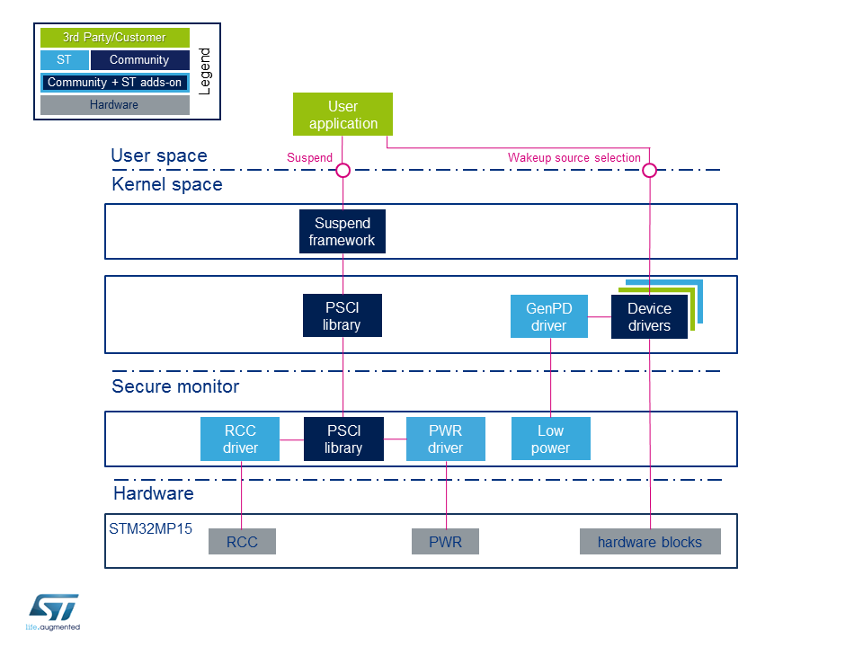
The user application issues a suspend request to the kernel. This request is handled by the suspend Framework, which notifies all the device drivers to prepare for low-power entry. It then calls the PSCI service.
2.2. STM32MP2 series[edit source]
The "System-Wide Power Management" is supported:
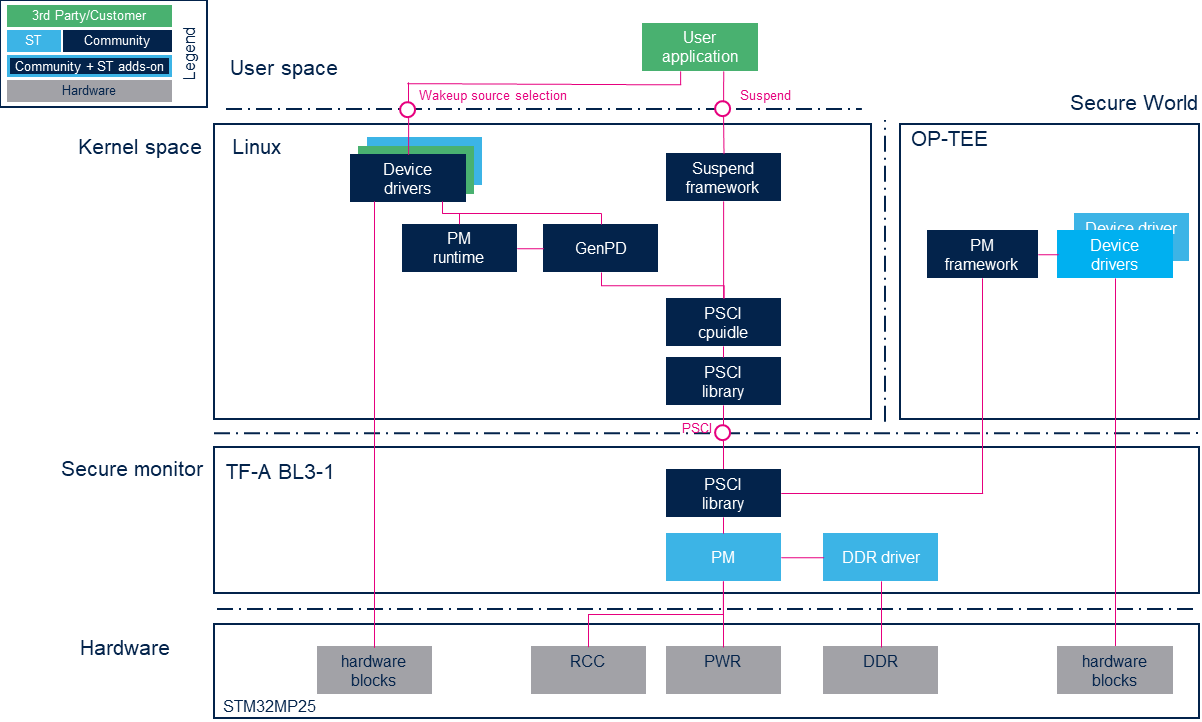
When the user application sent a suspend request to the kernel (static), it is treated by the suspend framework with the PSCI suspend support.
For OS initiated low power mode (dynamic), the application idle is detected when the Linux scheduler has no thread to run and treated by CPUIdle PSCI driver and the low power mode is selected with generic power domains (GenPD).
2.3. Component description[edit source]
Kernel components for low power:
- Suspend framework: this framework schedules the overall sequence by stopping all the ongoing tasks
- GenPD: generic power domain framework, based on runtime PM
- GenPD driver: this STMicrolectronics driver is used for low-power mode selection according to the activated wakeup sources on STM32MP1 series.
- PM runtime: device activity framework, used by each device driver
- PSCI library: this is a set of standardized functions to request a low-power service to the secure monitor
- PSCI cpuidle: CPU activity driver based on CPUIdle framework to handle Idle
- Device driver: any peripheral driver which needs to control power.
Secure monitor and secure world components (OP-TEE) on AArch32 platforms for STM32MP1 series :
- Low power driver: the role of this driver is to choose the low-power mode according to the programmed wakeup source(s)
- PWR driver: this driver is responsible for configuring the low-power mode
- RCC driver: this driver handles the circuit secure clocks
- PSCI libray: generic PSCI stack
Secure world components (OP-TEE) on AArch64 platforms for STM32MP2 series:
- PM framework: call the low-power callback of each device on the call of TF-A BL31 hooks.
- Device drivers: driver of secure device
Secure monitor components (TF-A BL31) on AArch64 platforms for STM32MP2 series
- PM manage PSCI topology and modes and DDR self refresh
- PSCI libray: generic PSCI stack
- DDR driver: DDR driver
STM32 peripherals (Hardware):
2.4. API description[edit source]
The suspend process is triggered from the user space through standard commands (see next chapter for details).
The system sleep control file is the state file, located under: /sys/power/
Further details can be found in admin-guide/pm/sleep-states.html and in power/interface.html.
The sysfs ABI are described in sysfs-power and sysfs-devices-power.
The device power API are described in driver-api/pm/index.html, in particular in driver-api/pm/devices.html.
3. Configuration[edit source]
The objective of this chapter is to explain how to configure the Linux kernel and device tree to have the Power Management (PM) framework activated.
3.1. Kernel configuration[edit source]
The Power Management framework is activated by default in ST deliveries.
It can be deactivated through the kernel menuconfig using Power management options/Suspend to RAM and standby: Menuconfig or how to configure kernel .
3.2. Device tree configuration[edit source]
3.2.1. STM32MP1 series[edit source]
The default system low-power mode mapping can be modified through the secure monitor device tree, as described OP-TEE documentation/devicetree/bindings/regulator/st,stm32mp1-pwr-reg.yaml .
Below an example in OP-TEE core/arch/arm/dts/stm32mp135f-dk.dts
 &pwr_regulators {
 	system_suspend_supported_soc_modes = <
 		STM32_PM_CSLEEP_RUN
 		STM32_PM_CSTOP_ALLOW_LP_STOP
 		STM32_PM_CSTOP_ALLOW_LPLV_STOP
 		STM32_PM_CSTOP_ALLOW_LPLV_STOP2
 		STM32_PM_CSTOP_ALLOW_STANDBY_DDR_SR
 	>;

 	system_off_soc_mode = <STM32_PM_SHUTDOWN>;
 };
3.2.2. STM32MP2 series[edit source]
The SoC device tree describes the PSCI topology in sub-nodes of cpus/domain-idle-states:
- for Linux in arch/arm64/boot/dts/st/stm32mp251.dtsi , one node for each PSCI_CPU_SUSPEND supported parameter (only the Stop1 modes):
domain-idle-states {
	STOP1: domain-stop1 {
		compatible = "domain-idle-state";
		arm,psci-suspend-param = <0x00000011>;
	};
	LP_STOP1: domain-lp-stop1 {
		compatible = "domain-idle-state";
		arm,psci-suspend-param = <0x0000021>;
	};
	LPLV_STOP1: domain-lplv-stop1 {
		compatible = "domain-idle-state";
		arm,psci-suspend-param = <0x00000211>;
	};
};
- for TF-A BL31 secure monitor, in fdts/stm32mp251.dtsi , one node by state supported in PSCI topology:
domain-idle-states {
	stop1 {
		compatible = "domain-idle-state";
		arm,psci-suspend-param = <0x00000011>;
	};
	lp-stop1 {
		compatible = "domain-idle-state";
		arm,psci-suspend-param = <0x00000021>;
	};
	lplv-stop1 {
		compatible = "domain-idle-state";
		arm,psci-suspend-param = <0x00000211>;
	};
	stop2 {
		compatible = "domain-idle-state";
		arm,psci-suspend-param = <0x40001333>;
	};
	lp-stop2 {
		compatible = "domain-idle-state";
		arm,psci-suspend-param = <0x40002333>;
	};
	lplv-stop2 {
		compatible = "domain-idle-state";
		arm,psci-suspend-param = <0x40023333>;
	};
	standby {
		compatible = "domain-idle-state";
		arm,psci-suspend-param = <0x40033333>;
	};
};
The selected PSCI power level is indicated to OP-TEE with Secure-EL1 Payload Dispatcher (SPD) PSCI hooks. The STPMIC25 driver in OP-TEE configures the different regulators according to the selected low power mode as described in device tree by regulator-state-XXX subnodes. Please refer to PMIC OP-TEE page for details and to OP-TEE device tree in core/arch/arm/dts/stm32mp257f-ev1.dts for configuration example.
The unsupported low power modes and associated references in domain-idle-states power domain nodes must be deleted from TF-A BL31 and Linux board device-tree files.
For example on board without STPMIC25, if the PWR_LP pins control the reduced voltage mode of the VDDCORE and VDDCPU regulators, then only LPLV-StopX modes can be reached. LP-StopX modes must be deleted.
- in TF-A BL31 device tree
/ {
	cpus {
		domain-idle-states {
			/delete-node/ lp-stop1;
			/delete-node/ lp-stop2;
		};
	};
};
- in Linux device tree (CLUSTER_PD
domain-idle-states = <&STOP1>, <&LP_STOP1>;for CLUSTER_PD in arch/arm64/boot/dts/st/stm32mp251.dts ):
/ {
	cpus {
		domain-idle-states {
			/delete-node/ domain-lp-stop1;
		};
	};
};

&CLUSTER_PD {
	domain-idle-states = <&STOP1>;
};
4. How to use the framework[edit source]
The power framework is managed with userfs API.
For Weston OpenSTLinux distribution, the direct access to sysfs must be avoided and must be replaced by systemctl command to correctly stop the systemd services and avoid issues on next wake-up.
| Linux mode | userFS API | command | STM32MP1 series | STM32MP2 series |
|---|---|---|---|---|
| S2Idle Suspend-to-Idle (or freeze) |
echo freeze > /sys/power/state | with SuspendState=freeze in /etc/systemd/sleep.confsystemctl suspend |
not supported | Stop1 LP-Stop1 LPLV-Stop1 |
| S2RAM Suspend-to-RAM (or deep) |
echo mem > /sys/power/state[mem 1] | with SuspendState=mem in /etc/systemd/sleep.confsystemctl suspend |
Stop LPLV-Stop Standby |
Stop2 LP-Stop2 LPLV-Stop2 Standby1 |
| power off | shutdown -P now systemctl poweroff |
Standby (DDR off) | Standby2 VBAT |
- ↑ "deep" for S2RAM is the default suspend variants associated with the "mem" string in the ``state`` file
cat /sys/power/mem_sleep
s2idle [deep]
See next chapters for low power more details on each family.
In OpenSTLinux, the low power modes are selected with devices activity and with activated wake up sources.
Each sysfs device in /sys/devices/ that supports wake up contains the file wakeup in a device's power sub directory. The file contains wake up trigger's status and can be written to as well. See device page to known the sysfs path in platform sub-directory and you can foudn all the possible wake up with:
find /sys/devices/platform | grep 'power/wakeup$'
You can check or control the wake up source with:
 cat /sys/devices/platform/<device>/power/wakeup
 echo enabled > /sys/devices/platform/<device>/power/wakeup
 echo disabled > /sys/devices/platform/<device>/power/wakeup
The platform also selects the allowed modes depending also the coprocessor state, so you need to call the expected low-power mode for MCU side or stop the MCU firmware. Please refer to Coprocessor power management for Arm® Cortex®-M commands or the MCU firmware can also be stopped before entering in low power (it is mandatory if this firmware is running in DDR).
4.1. Examples[edit source]
With default wake up source (RTC, Wakeup pins), the deepest platform mode is selected: Standby on STM32MP1 series / Standby1 on On STM32MP2 series.
The activation of other wake-up sources prevents entering into this deepest low-power mode.
4.1.1. PWR WKUP pins[edit source]
If PWR wake-up pins are enabled, for example see the WKUP button on STMicroelectronics boards, you can directly use the next command to call the low power entry:
 systemctl suspend                      for weston
 echo mem > /sys/power/state            for distribution without systemctl
Press the WKUP button on STMicroelectronics boards to wake up the board.
4.1.2. RTC wake up[edit source]
The RTC wake up is activated by default in Linux (/sys/devices/platform/*/*.rtc/power/wakeup), so you just need to program the alarm.
The tools rtcwake is used to enter a system sleep state until specified wake up time, for example 5 seconds with:
rtcwake --date +5sec -m mem
4.1.3. Serial wake-up[edit source]
With USART wake-up enabled, the low-power mode is limited to
- LPLV-Stop on STM32MP13x lines

- LP-Stop on STM32MP15x lines
- LP-Stop2 on STM32MP2 series.
Enable serial wake up on associated TTY wake up source, for example
echo enabled > /sys/class/tty/ttySTM0/power/wakeup
Call the low-power entry command
 systemctl suspend                      for weston
 echo mem > /sys/power/state            for distribution without systemctl
The MPU is now in low power mode (LP-Stop/LPLV-Stop/LP-Stop2) and can be woken up by sending a character to the console.
4.1.4. GPIO wake-up[edit source]
For GPIO wake-up enabled, the low-power mode is limited at LPLV-Stop on STM32MP1 series / LPLV-Stop2 on STM32MP2 series.
To enable test GPIO wake up, adds the wake up support with the property wakeup-source on a GPIO button (comaptible "gpio-keys") and is enabled in Linux by default (refer to Overview of GPIO pins for more details).
This property is not present on GPIO button in Linux device tree for St Microelectronics, so you just need to add it:
- STM32MP13x lines
&user-pa13 {
	wakeup-source;
};
- STM32MP15x lines
/ {
	gpio-keys {
		compatible = "gpio-keys";
		/* gpio needs vdd core in retention for wakeup */
		power-domains = <&pd_core_ret>;

		button-1 {
				label = "PA13";
				linux,code = <BTN_1>;
				gpios = <&gpioa 13 (GPIO_ACTIVE_LOW | GPIO_PULL_UP)>;
				wakeup-source;
		};
	};
- STM32MP25x lines
&button-user-1 {
	wakeup-source;
};
Call the low-power entry command:
 systemctl suspend                      for weston
 echo mem > /sys/power/state            for distribution without systemctl
The MPU is now in low power mode (LPLV-Stop or LPLVStop2) and you can wake up by the GPIO button.
You can dynamically check and deactivate the wake up capability for GPIO associated to the button.
cat /sys/class/gpio/gpio<n>/power/wakeup
echo enabled > /sys/class/gpio/gpio<n>/power/wakeup
4.1. Low-power modes on STM32MP1 series[edit source]
Refer to STM32MP13 reference manuals or STM32MP15 reference manuals for the full description of low-power modes.
The modes are handled by the RCC and the PWR peripherals.
Only the Suspend-to-RAM (S2RAM) target is supported for STM32MP1 series: the whole system activity is stopped and a low-power mode is entered. The software selects the deepest mode according to the activated wakeup source(s).
STM32MP1 series STMicroelectronics deliveries propose a default mapping of the low-power modes for each type of board, this default mapping can be changed thanks to the device tree as explain in the previous paragraph.
4.1.1. On STM32MP13x lines [edit source]
The table below summarizes the device hardware states corresponding to each low-power mode.
| MPU mode | Platform mode | VDDCORE state | VDDCPU state | Clocks state |
|---|---|---|---|---|
| CRun | Run | On | On | On |
| CStop | Stop/LPLV-Stop | On/Retention | On/Retention | Off/Off |
| CStandby | Stop/LPLV-Stop/LPLVL-STOP2/Standby | On/Retention/Retention/Off | On/Retention/Off/Off | Off/Off/Off/Off |
The following tables give the list of wake-up sources available in each mode.
| Platform mode | Available wake-up sources |
|---|---|
| Stop | BOR, PVD, AVD, Vbat mon, Temp mon, HSE CSS, LSE CSS, RTC, TAMP, USBH, OTG, ETH, USART, I2C, SPI, DTS, LPTIM, IWDG, GPIO, Wakeup pins (from PWR) |
| LPLV-Stop LPLV-Stop2 |
BOR, PVD, AVD, Vbat mon, Temp mon, LSE CSS, RTC, TAMP, USART, I2C, SPI, DTS, LPTIM, IWDG, GPIO, Wakeup pins (from PWR) |
| Standby | BOR, Vbat mon, Temp mon, LSE CSS, RTC, TAMP, IWDG, Wakeup pins (from PWR) |
4.1.2. On STM32MP15x lines [edit source]
The AN5109 low-power application note also gives much more information on these modes, including:
- the detailed description of the operating modes,
- the low-power mode entry and exit sequences,
- the low-power mode control registers.
- the wake-up sources and the software mechanism that ensures the consistency between the low-power mode and the activated wake-up source,
The table below summarizes the device hardware states corresponding to each low-power mode.
The term "subsystem" either refers to Arm® Cortex®-A7 (also called MPU) or to Arm® Cortex®-M4 (also called MCU). A mode prefixed by 'C' corresponds to a subsystem mode.
| Level | Mode | VDDCORE state | Subsystem Clocks state |
|---|---|---|---|
| MPU Subsystem | MPU CRun | on | on |
| MPU CStop | on | off | |
| MPU CStandby | on | off | |
| MCU Subsystem | MCU CRun | on | on |
| MCU CStop | on | off |
A platform mode is the combination of MPU and MCU modes.
| MPU mode | MCU mode | Platform mode | VDDCORE state | Clocks state |
|---|---|---|---|---|
| CRun/CStop/CStandby | CRun | Run | On | On |
| CStop/CStandby | CStop | Stop (LPDS = 0) | On | Off |
| CStop/CStandby | CStop | LP-Stop or LPLV-Stop (LPDS = 1) | Retention | Off |
| CStandby | CStop MCU PDDS = 1 |
Standby | Off | Off |
The following tables give the list of wake-up sources available in each mode.
| Plaform mode | Available wake-up sources |
|---|---|
| Stop LP-Stop |
BOR, PVD, AVD, Vbat mon, Temp mon, LSE CSS, RTC, TAMP, USB, CEC, ETH, USART, I²C, SPI, LPTIM, IWDG, GPIO, Wakeup pins (from PWR) |
| LPLV-Stop | BOR, PVD, AVD, Vbat mon, Temp mon, LSE CSS, RTC, TAMP, IWDG, GPIO, Wakeup pins (from PWR) |
| Standby | BOR, Vbat mon, Temp mon, LSE CSS, RTC, TAMP, IWDG, Wakeup pins (from PWR) |
This list of Wake-up capability peripheral for each mode is defined in the Table 35. Functionalities depending on system operating mode of the STM32MP15 reference manuals.
4.2. Low-power modes on STM32MP2 series[edit source]
Refer to STM32MP25 reference manuals for the full description of low-power modes.
The AN5726 Guidelines for using low-power modes on STM32MP2 MPU also gives much more information on these modes and on associated the wake-up sources.
| System mode | Linux Command | Power consumption | Wake-up time | VDDCPU | VDDCORE | DDR state |
|---|---|---|---|---|---|---|
| Stop1 | freeze (s2idle) |
Medium | Low | ON | ON | SR, VTT on |
| LP-Stop1 | Medium | Low | SR, VTT off | |||
| LPLV-Stop1 | Medium | Medium | ON (reduced) | ON (reduced) | ||
| Stop2 | mem (deep) |
Low | Low | OFF | ON | SR, VTT off |
| LP-Stop2 | Low | Medium | ||||
| LPLV-Stop2 | Low | Medium | ON (reduced) | |||
| Standby1 | Low | High | OFF | |||
| Standby2 | shutdown | Very-Low | High | Off | ||
| VBAT | Very-Low | Very-High |
OpenSTLinux sets the DDR in Self Refresh mode (SR) in all the low-power modes except power off (Standby2 and VBAT). For LP-Stop1 and LP-Stop2 modes, the DDR VTT supply is also switched off on STMicroelectronics reference design thought the PWR_LP signal connected to PWRCTRL1 pin of STPMIC25.
This list of Wake-up capability peripheral for each mode is defined in the Table 94. Functionalities depending on system operating mode of the STM32MP25 reference manuals.
The following tables give the list of wake-up sources available in each mode.
| Plaform mode | Available wake-up sources |
|---|---|
| Stop1/2 and LP-Stop1/2 |
Group1 : Group2 + HPDMAx (x = 1, 2, 3), HSI frequency monitoring, USB, UCPD1, ETHx (x = 1,2), USARTx (x = 1 to 9), I2Cx (x = 1 to 7), I3Cx (x = 1 to 3), SPIx (x = 1 to 7), DTS, LPTIMx (x = 1, 2) |
| LPLV-Stop1/2 | Group2 : Group3 + PVD, PVM, GPIOs |
| Standby1 | Group3 : Group4 + CPU3, DBG, LPDMA, LPUART1[note 1], I2C8[note 1], I3C4[note 1], SPI8[note 1], ADF1[note 1], LPTIMy (y = 3, 4, 5), WWDG2, MBOX2, HSEM, GPIOZ |
| Standby2 | Group4 : Group5 + 6 x WKUP pins |
| VBAT | Group5 : BOR, VBATH/VBATL, TEMPH/TEMPL, LSE CSS, RTC/auto wake-up, tamper pins, IWDGx |
4.2.1. PSCI topology[edit source]
The low power modes for STM32MP2 use the PSCI stack in TF-A BL31, including the PSCI OSI mode (v2.9).
The PSCI topology is defined in TF-A PM driver: plat/st/stm32mp2/stm32mp2_pm.c .
Each low power more is associated to a PSCI State-id, which uses the ARM Recommended StateID Encoding with OS initiated support, based on the PSCI state system topology defined in plat/st/stm32mp2/include/platform_def.h with:
PLAT_MAX_PWR_LVL= 4, for Core(0), D1(1), D1LPLV(2), D2(3), D2_LPLV(3)PLAT_MIN_SUSPEND_PWR_LVL=2, limit level forPSCI_CPU_SUSPENDsupportPLAT_NUM_PWR_DOMAINS= 6 (2 cores and 4 power level)
and with the power domain states:
STM32MP_LOCAL_STATE_RUN(0)STM32MP_LOCAL_STATE_RET(1)STM32MP_LOCAL_STATE_LP(2)STM32MP_LOCAL_STATE_OFF(3)
For PSCI suspend requests, STM32MP25 supports 5 power levels in the PSCI topology to handle the regulators configuration done in OP-TEE for STPMIC25, in particular to differentiate the voltages for LP and the LPLV modes.
The composite PSCI State-id are used in PSCI_CPU_SUSPEND requests and in device tree (for S2Idle and for OS initiated support) and for used internal in TF-A BL31 for PSCI_CPU_SUSPEND request (Deep).
This State-id encoding use the extended format and a simple additive composition method, with one nibble as a local state index for each power level (bits 27:0) and StateType(bit 30):
| PSCI request | Name | State-id | StateType | D2_LPLV | D2 | D1_LPLV | D1 | Core |
|---|---|---|---|---|---|---|---|---|
| PSCI_CPU_SUSPEND | Sleep (WFI) | 0x00000001 | STANDBY | RUN | RUN | RUN | RUN | RET |
| Stop1 | 0x00000011 | STANDBY | RUN | RUN | RUN | RET | RET | |
| LP-Stop1 | 0x00000021 | STANDBY | RUN | RUN | RUN | LP | RET | |
| LPLV-Stop1 | 0x00000211 | STANDBY | RUN | RUN | LP | RET | RET | |
| PSCI_SYSTEM_SUSPEND | Stop2 | 0x40001333 | POWERDOWN | RUN | RET | OFF | OFF | OFF |
| LP-Stop2 | 0x40002333 | POWERDOWN | RUN | LP | OFF | OFF | OFF | |
| LPLV-Stop2 | 0x40023333 | POWERDOWN | LP | OFF | OFF | OFF | OFF | |
| Standby | 0x40002333 | POWERDOWN | OFF | OFF | OFF | OFF | OFF |
4.2.2. PSCI in Linux (PSCI_CPU_SUSPEND)[edit source]
In Linux the power domain and associated low power modes for OS initiated mode are described in SoC device tree (in arch/arm64/boot/dts/st/stm32mp251.dtsi and in arch/arm64/boot/dts/st/stm32mp253.dtsi ) using the hierarchical model as described in Documentation/devicetree/bindings/arm/psci.yaml .
/ {
	cpus {
		idle-states {
			entry-method = "psci";

			CPU_PWRDN: cpu-power-down {
				compatible = "arm,idle-state";
				arm,psci-suspend-param = <0x00000001>;
			};
		};

		domain-idle-states {
			STOP1: domain-stop1 {
				compatible = "domain-idle-state";
				arm,psci-suspend-param = <0x00000011>;
			};

			LP_STOP1: domain-lp-stop1 {
				compatible = "domain-idle-state";
				arm,psci-suspend-param = <0x0000021>;
			};

			LPLV_STOP1: domain-lplv-stop1 {
				compatible = "domain-idle-state";
				arm,psci-suspend-param = <0x00000211>;
			};
		};
	};

	psci {
		compatible = "arm,psci-1.0";
		method = "smc";
		CPU_PD0: power-domain-cpu0 {
			#power-domain-cells = <0>;
			domain-idle-states = <&CPU_PWRDN>;
			power-domains = <&CLUSTER_PD>;
		};
		CPU_PD1: power-domain-cpu1 {
			#power-domain-cells = <0>;
			domain-idle-states =  <&CPU_PWRDN>;
			power-domains = <&CLUSTER_PD>;
		};
		CLUSTER_PD: power-domain-cluster {
			#power-domain-cells = <0>;
			domain-idle-states = <&STOP1>, <&LP_STOP1>;
			power-domains = <&RET_PD>;
		};
		RET_PD: power-domain-retention {
			#power-domain-cells = <0>;
			domain-idle-states = <&LPLV_STOP1>;
		};
	};
This power domain hierarchy is used in generic power domain (GenPD) for S2IDLE request and for dynamic power management, based PSCI OS initiated mode PM runtime: Linux kernel selects the lowest possible low power mode with the associated PSCI State Id, according the state of each power domain (device in the power domain is running, wake-up source is activated) and which respects the OS constraint (wake-up latency in OS initiated mode for example).
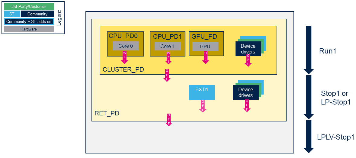
The devices are assigned to a domain in Soc device tree according the Table 94. Functionalities depending on system operating mode of the reference manuals (autonomous mode is not managed in OpenSTLinux).
- CLUSTER_PD for peripherals not functional in "Stop1/2 and LP-Stop1/2"
- RET_PD for peripherals not functional in "LPLV-Stop1/2"
The EXTI1 driver manages also the activated wake up source: LPLV-Stop1 mode is not not allowed for Group2 wake up source.
The dynamic power management is based on driver activity, with device PM runtime and GenPD, so you need to stop ALL the STM32MP25 peripherals activity, including console to allow low power modes.
4.2.3. PSCI in TF-A (PSCI_SYSTEM_SUSPEND)[edit source]
For deep request the PSCI_SYSTEM_SUSPEND is sent to T-FA when the secondary core is stopped and all the process are frozen. The activated wake-up are consolidated in TF-A BL31 to select the lowest POWERDOWN supported mode in stm32_get_sys_suspend_power_state() .
If a low power mode is not supported by a board design, it must be removed in TF-A BL31 device tree.
You can limit the maximum supported mode with wake-up sources, but you can't force Stop2 mode by Linux command if LP-Stop2 is supported (same functionalities, same supported wake-up sources).
To debug purpose, you can force the selected mode in stm32_get_sys_suspend_power_state(), for example:
/* Search the max supported POWERDOWN modes  <= max_pwr_state */
for (i = ARRAY_SIZE(stm32mp_supported_pwr_states) - 1U; i > 0U; i--) {
	pwr_state = stm32mp_supported_pwr_states[i];
	if ((pwr_state != 0U) && (pwr_state <= max_pwr_state) &&
		(psci_get_pstate_type(pwr_state) == PSTATE_TYPE_POWERDOWN)) {
	break;
	}
}

pwr_state = PWRSTATE_STOP2;

state_id = psci_get_pstate_id(pwr_state);
or remove some states in TF-A device tree , for example remove LP-Stop2 mode to allow Stop2 selection:
/ {
	cpus {
		domain-idle-states {
			/delete-node/ lp-stop2;
		};
	};
};
5. Source code location[edit source]
The source files are located inside the Linux kernel.
- power core:
- power drivers:
- drivers/base/power
- GENPD driver: domain.c
- CPUIdle driver: drivers/cpuidle/
- PSCI drivers:
- STM32MP specific driver:
- drivers/soc/st/stm32_pm_domain.c for STM32MP1 series
- drivers/base/power
- bindings:
For the framework used in Linux power management, see the associated pages:
And drivers in other software component for each internal peripheral or external component are described in the associated pages:
6. How to trace and debug[edit source]
The suspend/resume process execution is logged in the MPU console. It gives useful information on the platform state (sleeping or active).
 root@stm32mp1:~# echo mem > /sys/power/state
 [ 1072.267571] PM: suspend entry (deep)
 [ 1072.269687] PM: Syncing filesystems ... done.
 [ 1072.279114] Freezing user space processes ... (elapsed 0.008 seconds) done.
 [ 1072.292835] OOM killer disabled.
 [ 1072.296046] Freezing remaining freezable tasks ... (elapsed 0.001 seconds) done.
 [ 1072.303431] Suspending console(s) (use no_console_suspend to debug)
 [ 1072.332520] dwc2 49000000.usb-otg: suspending usb gadget configfs-gadget
 [ 1072.332537] dwc2 49000000.usb-otg: dwc2_hsotg_ep_disable: called for ep0
 [ 1072.332546] dwc2 49000000.usb-otg: dwc2_hsotg_ep_disable: called for ep0
 [ 1072.468536] Disabling non-boot CPUs ...
 [ 1072.507876] CPU1 killed.
 [ 1072.509635] Enabling non-boot CPUs ...
 [ 1072.510508] CPU1 is up
 [ 1072.527553] dwmac4: Master AXI performs any burst length
 [ 1072.527583] stm32-dwmac 5800a000.ethernet eth0: No Safety Features support found
 [ 1072.527621] stm32-dwmac 5800a000.ethernet eth0: ERROR failed to create debugfs directory
 [ 1072.527631] stm32-dwmac 5800a000.ethernet eth0: stmmac_hw_setup: failed debugFS registration
 [ 1072.588234] dwc2 49000000.usb-otg: resuming usb gadget configfs-gadget
 [ 1072.738469] OOM killer enabled.
 [ 1072.741575] Restarting tasks ... done.
 [ 1072.752596] PM: suspend exit
Get more debug information from the console with the following commands:
echo N > /sys/module/printk/parameters/console_suspend
This command allows to see the last linux kernel trace and also the PSCI stack traces, in OP-TEE for STM32MP1 and the the TF-A BL31 traces for STM32MP2 (which indicate the selected low power mode).
You can also activate the dynamic debug in Linux:
echo "func pm_dev_dbg +p" > /sys/kernel/debug/dynamic_debug/control
 echo "func pm_pr_dbg +p" > /sys/kernel/debug/dynamic_debug/control
 echo "func dpm_show_time +p" > /sys/kernel/debug/dynamic_debug/control
 echo "func s2idle_loop +p" > /sys/kernel/debug/dynamic_debug/control
And use power sysfs sysfs-devices-power, for example:
 echo 1 > /sys/power/pm_debug_messages
 echo 0 > /sys/power/pm_async
You can also activate PM_DEBUG and PM_TRACE.
To go further see the kernel documentation power/basic-pm-debugging.rst and power/s2ram.rst.
It is also possible to monitor the hardware signals related to the system low-power modes thanks to the HDP internal peripheral.
Please refer to HDP Linux driver for its configuration.
7. To go further[edit source]
Refer to reference manual for a detailed description of low-power modes and peripheral wakeup sources:
The next application notes gives additional information on the hardware settings used for low-power management:
8. References[edit source]
- ↑ Arm Power State Coordination Interface (PSCI):
https://developer.arm.com/documentation/den0022 - ↑ Arm System Control and Management Interface Platform Design Document (SCMI) specification:
https://developer.arm.com/documentation/den0056
Arm® is a registered trademark of Arm Limited (or its subsidiaries) in the US and/or elsewhere. ![]()
Arm® is a registered trademark of Arm Limited (or its subsidiaries) in the US and/or elsewhere. ![]()