This article gives information about the Linux® V4L2 camera framework.
1. Framework purpose[edit source]
The V4L2 Linux kernel framework[1] allows to control both an external camera sensor and the camera interface in order to capture raw frames in various pixel formats or encoded stream data such as JPEG.
This could be typically used, with the help of other Linux multimedia frameworks and applications, to take snapshot, to make preview, to make a video recording or even remotely stream images from the camera sensor.
2. System overview[edit source]
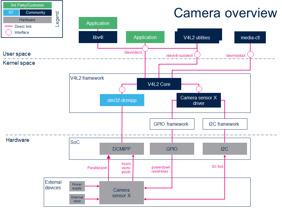
2.1. Component description[edit source]
- media-ctl (User space)
A V4L2 utility relying on Media Controller Linux kernel interface[2] aiming to configure and link each sub devices composing the camera subsystem in order to configure it.
- Application (User space)
Any application relying on V4L2 Linux kernel interface[3] or libv4l abstraction layer. GStreamer framework provides such application.
- V4L2 utilities (User space)
A set of tools to test, configure and use the whole camera subsystem, including the external camera sensor and the camera interface. V4l2-ctl is one of the most usefull utility.
- V4L2 libraries (libv4l) (User space)
A set of libraries on top of the V4L2 Linux kernel interface[3] which abstract the kernel interface in order to simplify, keep compatibility or add some hooks between V4L-based applications and the V4L2 kernel interface.
- V4L2 core (Kernel space)
This layer represents the standard Linux kernel V4L2 Framework.
- stm32-dcmipp (Kernel space)
This V4L2 DCMIPP Linux device driver handles the DCMIPP hardware block.
- Camera sensor X driver (Kernel space)
This V4L2 Linux device driver handles the camera sensor X external peripheral, handles some GPIOs lines and potentially power supplies to power-up/down the camera sensor. The communication with camera sensor is done through the i2c bus.
- DCMIPP (Hardware)
The Digital Camera Memory Interface Pixel Processor hardware block.
- Camera sensor X (Hardware)
The camera sensor external peripheral.
2.2. APIs description[edit source]
The V4L2 userland API is documented in the Linux Media subsystem documentation[3]
The V4L2 kernel framework internal API is documented in the V4L2 Kernel Support section of the Linux Kernel documentation[4]
The Media Controller API is documented in the Linux Media subsystem documentation[2]
3. Configuration[edit source]
3.1. Kernel configuration[edit source]
The STM32 camera interface and OV5640 camera sensor are enabled by default in STMicroelectronics deliveries.
Nevertheless this is not the case when using upstream kernel version. In this case, the DCMI V4L2 driver can be enabled using Linux kernel menuconfig tool:
[*] Device Drivers --->
    [*] Multimedia support --->
        [*] V4L platform devices  --->
            [*] STM32 Digital Camera Memory Interface Pixel Processor (DCMIPP) support
The external camera sensor connected to the camera interface must also be enabled, here is an example with the OV5640 Omnivision camera sensor located on the MB1723 camera daughter board[5] connected to the CN1 camera connector[6] of the STM32MP13 discovery board[7]:
[*] Device Drivers --->
    [*] Multimedia support --->
        I2C Encoders, decoders, sensors and other helper chips  --->
            [*] OmniVision OV5640 sensor support
DCMIPP hardware block interconnects with the camera sensor connected on CN1 through the MIPID02 CSI-2 to parallel bridge soldered on STM32MP13 discovery board. Hence MIPID02 driver must be enabled too:
[*] Device Drivers --->
    [*] Multimedia support --->
        Media ancillary drivers  --->
            Miscellaneous helper chips  --->
               [*] STMicroelectronics MIPID02 CSI-2 to PARALLEL bridge
3.2. Device tree configuration[edit source]
Refer to DCMIPP device tree configuration article for a complete view of DCMIPP & sensor configuration thanks to Linux kernel device tree mechanism.
4. How to use the framework[edit source]
The use cases described here are enabled using media-ctl, V4l2-ctl, gst-launch or gst-play command line utilities.
4.1. List the video devices and their capabilities[edit source]
List all the available video devices using --list-devices option:
v4l2-ctl --list-devices
dcmipp_bytecap (platform:dcmipp):
        /dev/video0
        /dev/media0
If several devices are available, use -d option after any V4l2-ctl commands to target a specific device. If -d option is not specified, /dev/video0 is targeted by default.
In order to have information on a specific device, use -D option:
v4l2-ctl -d /dev/video0 -D
Driver Info:
        Driver name      : dcmipp
        Card type        : dcmipp_bytecap
        Bus info         : platform:dcmipp
        Driver version   : 5.15.0
        Capabilities     : 0x85200001
                Video Capture
                Read/Write
                Streaming
                Extended Pix Format
                Device Capabilities
        Device Caps      : 0x05200001
                Video Capture
                Read/Write
                Streaming
                Extended Pix Format
Media Driver Info:
        Driver name      : dcmipp
        Model            : DCMIPP MDEV
        Serial           :
        Bus info         : platform:dcmipp
        Media version    : 5.15.0
        Hardware revision: 0x00000000 (0)
        Driver version   : 5.15.0
Interface Info:
        ID               : 0x03000009
        Type             : V4L Video
Entity Info:
        ID               : 0x00000007 (7)
        Name             : dcmipp_dump_capture
        Function         : V4L2 I/O
        Pad 0x01000008   : 0: Sink
          Link 0x0200000d: from remote pad 0x1000006 of entity 'dcmipp_dump_postproc': Data, Enabled, Immutable
4.2. Get the topology of camera subsystem[edit source]
Print the topology of camera subsystem using -p media-ctl option:
media-ctl -p
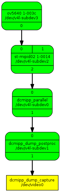
Media controller API version 5.15.0

Media device information
------------------------
driver          dcmipp
model           DCMIPP MDEV
serial
bus info        platform:dcmipp
hw revision     0x0
driver version  5.15.0

Device topology
- entity 1: dcmipp_parallel (2 pads, 2 links)
            type V4L2 subdev subtype Unknown flags 0
            device node name /dev/v4l-subdev0
        pad0: Sink
                [fmt:RGB565_2X8_LE/640x480 field:none]
                <- "st-mipid02 1-0014":2 [ENABLED,IMMUTABLE]
        pad1: Source
                [fmt:RGB565_2X8_LE/640x480 field:none]
                -> "dcmipp_dump_postproc":0 [ENABLED,IMMUTABLE]

- entity 4: dcmipp_dump_postproc (2 pads, 2 links)
            type V4L2 subdev subtype Unknown flags 0
            device node name /dev/v4l-subdev1
        pad0: Sink
                [fmt:RGB565_2X8_LE/640x480 field:none]
                <- "dcmipp_parallel":1 [ENABLED,IMMUTABLE]
        pad1: Source
                [fmt:RGB565_2X8_LE/640x480 field:none
                 crop.bounds:(0,0)/640x480
                 crop:(0,0)/640x480]
                -> "dcmipp_dump_capture":0 [ENABLED,IMMUTABLE]

- entity 7: dcmipp_dump_capture (1 pad, 1 link)
            type Node subtype V4L flags 0
            device node name /dev/video0
        pad0: Sink
                <- "dcmipp_dump_postproc":1 [ENABLED,IMMUTABLE]

- entity 15: st-mipid02 1-0014 (3 pads, 2 links)
             type V4L2 subdev subtype Unknown flags 0
             device node name /dev/v4l-subdev2
        pad0: Sink
                [fmt:RGB565_2X8_LE/640x480 field:none colorspace:srgb xfer:srgb ycbcr:601 quantization:full-range]
                <- "ov5640 1-003c":0 [ENABLED,IMMUTABLE]
        pad1: Sink
        pad2: Source
                [fmt:RGB565_2X8_LE/640x480 field:none colorspace:srgb xfer:srgb ycbcr:601 quantization:full-range]
                -> "dcmipp_parallel":0 [ENABLED,IMMUTABLE]

- entity 21: ov5640 1-003c (1 pad, 1 link)
             type V4L2 subdev subtype Sensor flags 0
             device node name /dev/v4l-subdev3
        pad0: Source
                [fmt:RGB565_2X8_LE/640x480@1/15 field:none colorspace:srgb xfer:srgb ycbcr:601 quantization:full-range]
                -> "st-mipid02 1-0014":0 [ENABLED,IMMUTABLE]
This gives either the current links between camera subdevices and each subdevice current pads configuration: format, resolution, framerate...
This topology can also be displayed in a human readable graphical form thanks to --print-dot option:
media-ctl --print-dot > graph.dot
Retrieve then this .dot file into your host PC in order to convert it to .png:
dot -Tpng -Nfontname=Roboto -Nfontsize=10 -Efontname=Roboto -Efontsize=10 graph.dot > graph.png
4.3. Camera subsystem setup[edit source]
In order to be able to capture frames from video device node with v4l2-ctl or GStreamer, the camera subsystem must be first configured. To do so use media-ctl --set-v4l2 command giving the subdevice name & pad, the desired format, resolution and framerate:
media-ctl -d /dev/media0 --set-v4l2 "'ov5640 1-003c':0[fmt:RGB565_2X8_LE/640x480@1/30 field:none]"
Configuration must be done from source to sink. Here is a configuration allowing to capture RGB565 480x272 frames (the display size of the MP13 discovery board):
media-ctl -d /dev/media0 --set-v4l2 "'ov5640 1-003c':0[fmt:RGB565_2X8_LE/640x480@1/30 field:none]"
media-ctl -d /dev/media0 --set-v4l2 "'dcmipp_parallel':0[fmt:RGB565_2X8_LE/640x480]"
media-ctl -d /dev/media0 --set-v4l2 "'dcmipp_dump_postproc':0[fmt:RGB565_2X8_LE/640x480]"
media-ctl -d /dev/media0 --set-v4l2 "'dcmipp_dump_postproc':1[fmt:RGB565_2X8_LE/640x480]"
media-ctl -d /dev/media0 --set-v4l2 "'dcmipp_dump_postproc':1[crop:(80,104)/480x272]"
Sensor is configured in 640x480 RGB565 at 30fps, then DCMIPP is configured to crop area 480x272 in the middle of the 640x480 frame output by sensor. Configuration can be read back displaying the topology of graph, see #Get the topology of camera subsystem Then any application that read frames from V4L2 video device node can be executed:
gst-launch-1.0 v4l2src ! video/x-raw, format=RGB16, width=480,height=272, framerate=30/1 ! queue ! waylandsink fullscreen=true
4.4. Controlling camera sensor[edit source]
In order to control camera sensor, its corresponding entity device node must be found in the topology. To do so, the first entity of the graph must be found, ie the entity having no sink pad:
- entity 21: ov5640 1-003c (1 pad, 1 link)
             type V4L2 subdev subtype Sensor flags 0
             device node name /dev/v4l-subdev3
        pad0: Source
                [fmt:RGB565_2X8_LE/640x480@1/15 field:none colorspace:srgb xfer:srgb ycbcr:601 quantization:full-range]
                -> "st-mipid02 1-0014":0 [ENABLED,IMMUTABLE]
Here it is /dev/v4l-subdev3.
Use then V4l2-ctl with -L option to get the list of supported controls:
v4l2-ctl -d /dev/v4l-subdev3 -L
User Controls
                       contrast 0x00980901 (int)    : min=0 max=255 step=1 default=0 value=0 flags=slider
                     saturation 0x00980902 (int)    : min=0 max=255 step=1 default=64 value=64 flags=slider
                            hue 0x00980903 (int)    : min=0 max=359 step=1 default=0 value=0 flags=slider
        white_balance_automatic 0x0098090c (bool)   : default=1 value=1 flags=update
                    red_balance 0x0098090e (int)    : min=0 max=4095 step=1 default=0 value=0 flags=inactive, slider
                   blue_balance 0x0098090f (int)    : min=0 max=4095 step=1 default=0 value=0 flags=inactive, slider
                 gain_automatic 0x00980912 (bool)   : default=1 value=1 flags=update
                horizontal_flip 0x00980914 (bool)   : default=0 value=0
                  vertical_flip 0x00980915 (bool)   : default=0 value=0
           power_line_frequency 0x00980918 (menu)   : min=0 max=3 default=1 value=1
                                0: Disabled
                                1: 50 Hz
                                2: 60 Hz
                                3: Auto

Image Processing Controls
                 link_frequency 0x009f0901 (intmenu): min=0 max=8 default=0 value=2 flags=read-only
                                0: 63136800 (0x3c36420)
                                1: 83954880 (0x5010cc0)
                                2: 92145600 (0x57e07c0)
                                3: 126273600 (0x786c840)
                                4: 167909760 (0xa021980)
                                5: 184291200 (0xafc0f80)
                                6: 191116800 (0xb643600)
                                7: 335819520 (0x14043300)
                                8: 382233600 (0x16c86c00)
                     pixel_rate 0x009f0902 (int64)  : min=0 max=2147483647 step=1 default=92145600 value=46072800 flags=read-only
                   test_pattern 0x009f0903 (menu)   : min=0 max=4 default=0 value=0
                                0: Disabled
                                1: Color bars
                                2: Color bars w/ rolling bar
                                3: Color squares
                                4: Color squares w/ rolling bar
The control value can be changed thanks to --set-ctrl option, for example:
v4l2-ctl -d /dev/v4l-subdev3 --set-ctrl test_pattern=1
The control value can be changed dynamically. In the following example, the color bar is enabled/disabled while preview is running:
- Start preview in background
gst-launch-1.0 v4l2src ! "video/x-raw, format=RGB16, width=480, height=272, framerate=(fraction)30/1" ! queue ! waylandsink fullscreen=true -e &
- Then alternate the color bar activation or not
v4l2-ctl -d /dev/v4l-subdev3 --set-ctrl test_pattern=1;sleep 1;v4l2-ctl -d /dev/v4l-subdev3 --set-ctrl test_pattern=0;sleep 1;v4l2-ctl -d /dev/v4l-subdev3 --set-ctrl test_pattern=1;sleep 1;v4l2-ctl -d /dev/v4l-subdev3 --set-ctrl test_pattern=0;killall gst-launch-1.0
- Horizontal/vertical flip can also be changed while preview is running:
v4l2-ctl -d /dev/v4l-subdev3 --set-ctrl horizontal_flip=1;sleep 2;v4l2-ctl -d /dev/v4l-subdev3 --set-ctrl horizontal_flip=0;sleep 2;v4l2-ctl -d /dev/v4l-subdev3 --set-ctrl vertical_flip=1;sleep 2;v4l2-ctl -d /dev/v4l-subdev3 --set-ctrl vertical_flip=0;killall gst-launch-1.0
4.5. Set the pixel format, resolution and framerate[edit source]
Camera sensor only supports a discrete set of formats, resolutions and framerates that can be get thanks to v4l2-ctl options --list-subdev-mbus-codes, --list-subdev-framesizes and --list-subdev-frameintervals:
v4l2-ctl -d /dev/v4l-subdev3 --list-subdev-mbus-codes
ioctl: VIDIOC_SUBDEV_ENUM_MBUS_CODE (pad=0)
        0x4001: MEDIA_BUS_FMT_JPEG_1X8
        0x2006: MEDIA_BUS_FMT_UYVY8_2X8
        0x200f: MEDIA_BUS_FMT_UYVY8_1X16
        0x2008: MEDIA_BUS_FMT_YUYV8_2X8
        0x2011: MEDIA_BUS_FMT_YUYV8_1X16
        0x1008: MEDIA_BUS_FMT_RGB565_2X8_LE
        0x1007: MEDIA_BUS_FMT_RGB565_2X8_BE
        0x3001: MEDIA_BUS_FMT_SBGGR8_1X8
        0x3013: MEDIA_BUS_FMT_SGBRG8_1X8
        0x3002: MEDIA_BUS_FMT_SGRBG8_1X8
        0x3014: MEDIA_BUS_FMT_SRGGB8_1X8
v4l2-ctl -d /dev/v4l-subdev3 --list-subdev-framesizes pad=0
ioctl: VIDIOC_SUBDEV_ENUM_FRAME_SIZE (pad=0)
        Size Range: 160x120 - 160x120
        Size Range: 176x144 - 176x144
        Size Range: 320x240 - 320x240
        Size Range: 640x480 - 640x480
        Size Range: 720x480 - 720x480
        Size Range: 720x576 - 720x576
        Size Range: 1024x768 - 1024x768
        Size Range: 1280x720 - 1280x720
        Size Range: 1920x1080 - 1920x1080
        Size Range: 2592x1944 - 2592x1944
Framerate depends on resolution, so precise it when asking for frame intervals:
v4l2-ctl -d /dev/v4l-subdev3 --list-subdev-frameintervals pad=0,width=640,height=480
ioctl: VIDIOC_SUBDEV_ENUM_FRAME_INTERVAL (pad=0)
        Interval: 0.067s (15.000 fps)
        Interval: 0.033s (30.000 fps)
Now that camera sensor capabilities are known, the wanted configuration can be set in #Camera subsystem setup. For example here to make a QVGA preview at 15fps:
media-ctl -d /dev/media0 --set-v4l2 "'ov5640 1-003c':0[fmt:RGB565_2X8_LE/320x240@1/15 field:none]"
media-ctl -d /dev/media0 --set-v4l2 "'dcmipp_parallel':0[fmt:RGB565_2X8_LE/320x240]"
media-ctl -d /dev/media0 --set-v4l2 "'dcmipp_dump_postproc':0[fmt:RGB565_2X8_LE/320x240]"
media-ctl -d /dev/media0 --set-v4l2 "'dcmipp_dump_postproc':1[fmt:RGB565_2X8_LE/320x240]"
media-ctl -d /dev/media0 --set-v4l2 "'dcmipp_dump_postproc':1[crop:(0,0)/320x240]"
gst-launch-1.0 v4l2src ! video/x-raw, format=RGB16, width=320,height=240, framerate=15/1 ! queue ! autovideosink
Here is another example to capture 100 QVGA JPEG files at 30fps:
media-ctl -d /dev/media0 --set-v4l2 "'ov5640 1-003c':0[fmt:JPEG_1X8/320x240@1/30 field:none]"
media-ctl -d /dev/media0 --set-v4l2 "'dcmipp_parallel':0[fmt:JPEG_1X8/320x240]"
media-ctl -d /dev/media0 --set-v4l2 "'dcmipp_dump_postproc':0[fmt:JPEG_1X8/320x240]"
media-ctl -d /dev/media0 --set-v4l2 "'dcmipp_dump_postproc':1[fmt:JPEG_1X8/320x240]"
media-ctl -d /dev/media0 --set-v4l2 "'dcmipp_dump_postproc':1[crop:(0,0)/320x240]"
v4l2-ctl --set-fmt-video=width=320,height=240,pixelformat=JPEG --set-parm=30 --stream-mmap --stream-count=100 --stream-to=pics.jpeg
Replay using gst-play:
gst-play-1.0 pics.jpeg --videosink="videorate ! video/x-raw, framerate=30/1 ! autovideosink"
4.6. Grab a raw frame[edit source]
Capture a QVGA RGB565 raw frame on disk:
media-ctl -d /dev/media0 --set-v4l2 "'ov5640 1-003c':0[fmt:RGB565_2X8_LE/320x240@1/30 field:none]"
media-ctl -d /dev/media0 --set-v4l2 "'dcmipp_parallel':0[fmt:RGB565_2X8_LE/320x240]"
media-ctl -d /dev/media0 --set-v4l2 "'dcmipp_dump_postproc':0[fmt:RGB565_2X8_LE/320x240]"
media-ctl -d /dev/media0 --set-v4l2 "'dcmipp_dump_postproc':1[fmt:RGB565_2X8_LE/320x240]"
media-ctl -d /dev/media0 --set-v4l2 "'dcmipp_dump_postproc':1[crop:(0,0)/320x240]"
v4l2-ctl --set-fmt-video=width=320,height=240,pixelformat=RGBP --stream-mmap --stream-count=1 --stream-to=grab-320x240-rgb565.raw
In order to display it, this raw frame must be converted first to JPEG:
gst-launch-1.0 filesrc location= grab-320x240-rgb565.raw blocksize=153600 ! "video/x-raw, format=(string)RGB16, width=(int)320, height=(int)240, framerate=(fraction)30/1" ! videoconvert ! jpegenc ! filesink location=grab-320x240-rgb565.jpeg
Then weston-image utility can be used to display this JPEG file:
weston-image grab-320x240-rgb565.jpeg
4.7. Fullscreen preview[edit source]
media-ctl -d /dev/media0 --set-v4l2 "'ov5640 1-003c':0[fmt:RGB565_2X8_LE/640x480@1/30 field:none]"
media-ctl -d /dev/media0 --set-v4l2 "'dcmipp_parallel':0[fmt:RGB565_2X8_LE/640x480]"
media-ctl -d /dev/media0 --set-v4l2 "'dcmipp_dump_postproc':0[fmt:RGB565_2X8_LE/640x480]"
media-ctl -d /dev/media0 --set-v4l2 "'dcmipp_dump_postproc':1[fmt:RGB565_2X8_LE/640x480]"
media-ctl -d /dev/media0 --set-v4l2 "'dcmipp_dump_postproc':1[crop:(80,104)/480x272]"
gst-launch-1.0 v4l2src ! "video/x-raw, format=RGB16, width=480, height=272, framerate=(fraction)15/1" ! queue ! autovideosink -e
4.8. Take a picture[edit source]
Capture a 5Mp JPEG:
media-ctl -d /dev/media0 --set-v4l2 "'ov5640 1-003c':0[fmt:JPEG_1X8/640x480@1/15 field:none]"
media-ctl -d /dev/media0 --set-v4l2 "'ov5640 1-003c':0[fmt:JPEG_1X8/2592x1944@1/15 field:none]"
media-ctl -d /dev/media0 --set-v4l2 "'dcmipp_parallel':0[fmt:JPEG_1X8/2592x1944]"
media-ctl -d /dev/media0 --set-v4l2 "'dcmipp_dump_postproc':0[fmt:JPEG_1X8/2592x1944]"
media-ctl -d /dev/media0 --set-v4l2 "'dcmipp_dump_postproc':1[fmt:JPEG_1X8/2592x1944]"
media-ctl -d /dev/media0 --set-v4l2 "'dcmipp_dump_postproc':1[crop:(0,0)/2592x1944]"
v4l2-ctl --set-fmt-video=width=2592,height=1944,pixelformat=JPEG --stream-mmap --stream-count=1 --stream-skip=3 --stream-to=pic-5Mp.jpeg
Then display it:
weston-image pic-5Mp.jpeg
You can check the picture resolution using gst-typefind:
gst-typefind-1.0 pic-5Mp.jpeg
pic-5Mp.jpeg - image/jpeg, width=(int)2592, height=(int)1944, sof-marker=(int)0
4.9. Pictures streaming over network[edit source]
Refer to How to stream camera over network article to get some examples on how to stream camera content over network.
5. How to trace and debug[edit source]
5.1. How to monitor[edit source]
5.1.1. Check of devicetree configuration[edit source]
Here are some commands to verify that DCMIPP is enabled, check which camera sensor is used and log other details about devicetree configuration:
echo "#!/bin/bash" > dtdumpentry.sh;echo "hexdump -e '\"=\"'  -e '20/1 \"%c\"\"\t\"' -e '20/1 \"%02x\"\"\n\"' \$1" >> dtdumpentry.sh;chmod +x dtdumpentry.sh
echo "#!/bin/bash" > dtdump.sh;echo "find  \$1* -type f -print0 -exec ./dtdumpentry.sh {} \;" >> dtdump.sh;chmod +x dtdump.sh
rm devicetree.txt
echo "[devicetree]" >> devicetree.txt
echo "|-[dcmipp]" >> devicetree.txt
./dtdump.sh /proc/device-tree/soc/dcmi | sed 's/\/proc\/device-tree\/soc\//| |-/' >> devicetree.txt
echo "|" >> devicetree.txt
echo "|-[camera:" | tr -d "\n" >> devicetree.txt
cat /proc/device-tree/soc/i2c*/camera*/compatible >> devicetree.txt
echo "]" >> devicetree.txt
./dtdump.sh /proc/device-tree/soc/i2c*/camera* -type f -print0 -exec ./dtdump.sh {} \; | sed 's/\/proc\/device-tree\/soc\//| |-/' >> devicetree.txt
echo "|" >> devicetree.txt
echo "|-[mipi bridge:" | tr -d "\n" >> devicetree.txt
cat /proc/device-tree/soc/i2c*/*mipi*/compatible >> devicetree.txt
echo "]" >> devicetree.txt
./dtdump.sh /proc/device-tree/soc/i2c*/*mipi* -type f -print0 -exec ./dtdump.sh {} \; | sed 's/\/proc\/device-tree\/soc\//| |-/' >> devicetree.txt
echo "" >> devicetree.txt
cat devicetree.txt
[devicetree]
|-[dcmipp]
| |-dcmipp@5a000000/compatible=st,stm32mp13-dcmipp      73742c73746d33326d7031332d64636d69707000
| |-dcmipp@5a000000/clocks=�    000000050000008f
| |-dcmipp@5a000000/resets=5�   00000005000035c1
| |-dcmipp@5a000000/pinctrl-1=& 00000026
| |-dcmipp@5a000000/port/endpoint/hsync-active= 00000000
| |-dcmipp@5a000000/port/endpoint/vsync-active= 00000000
| |-dcmipp@5a000000/port/endpoint/remote-endpoint='     00000027
| |-dcmipp@5a000000/port/endpoint/pclk-max-frequency='  07270e00
| |-dcmipp@5a000000/port/endpoint/bus-width=    00000008
| |-dcmipp@5a000000/port/endpoint/pclk-sample=  00000000
| |-dcmipp@5a000000/port/endpoint/phandle=�     0000001d
| |-dcmipp@5a000000/port/endpoint/name=endpoint 656e64706f696e7400
| |-dcmipp@5a000000/port/name=port      706f727400
| |-dcmipp@5a000000/clock-names=kclk    6b636c6b00
| |-dcmipp@5a000000/status=okay 6f6b617900
| |-dcmipp@5a000000/interrupts=O�       000000000000004f00000004
| |-dcmipp@5a000000/phandle=^   0000005e
| |-dcmipp@5a000000/reg=Z�      5a00000000000400
| |-dcmipp@5a000000/pinctrl-0=% 00000025
| |-dcmipp@5a000000/name=dcmipp 64636d69707000
| |-dcmipp@5a000000/pinctrl-names=defaultsleep  64656661756c7400736c65657000
|
|-[camera:ovti,ov5640]
| |-i2c@4c006000/camera@3c/compatible=ovti,ov5640       6f7674692c6f763536343000
| |-i2c@4c006000/camera@3c/powerdown-gpios=�    0000001b0000000300000001
| |-i2c@4c006000/camera@3c/DOVDD-supply=        00000018
| |-i2c@4c006000/camera@3c/clocks=�     0000001e
| |-i2c@4c006000/camera@3c/port/endpoint/remote-endpoint=�      0000001f
| |-i2c@4c006000/camera@3c/port/endpoint/data-lanes=��  0000000100000002
| |-i2c@4c006000/camera@3c/port/endpoint/clock-lanes=   00000000
| |-i2c@4c006000/camera@3c/port/endpoint/phandle=�      0000001c
| |-i2c@4c006000/camera@3c/port/endpoint/name=endpoint  656e64706f696e7400
| |-i2c@4c006000/camera@3c/port/name=port       706f727400
| |-i2c@4c006000/camera@3c/clock-names=xclk     78636c6b00
| |-i2c@4c006000/camera@3c/status=okay  6f6b617900
| |-i2c@4c006000/camera@3c/reset-gpios=�        0000001b0000000400000001
| |-i2c@4c006000/camera@3c/phandle=K    0000004b
| |-i2c@4c006000/camera@3c/reg=<        0000003c
| |-i2c@4c006000/camera@3c/name=camera  63616d65726100
|
|-[mipi bridge:st,st-mipid02]
  |-i2c@4c006000/stmipi@14/compatible=st,st-mipid02     73742c73742d6d69706964303200
  |-i2c@4c006000/stmipi@14/clocks=�     00000019
  |-i2c@4c006000/stmipi@14/VDDIN-supply=        0000001a
  |-i2c@4c006000/stmipi@14/clock-names=xclk     78636c6b00
  |-i2c@4c006000/stmipi@14/ports/#address-cells=�       00000001
  |-i2c@4c006000/stmipi@14/ports/#size-cells=   00000000
  |-i2c@4c006000/stmipi@14/ports/port@2/endpoint/hsync-active=  00000000
  |-i2c@4c006000/stmipi@14/ports/port@2/endpoint/vsync-active=  00000000                   Minicom2.7Minicom2.7
  |-i2c@4c006000/stmipi@14/ports/port@2/endpoint/remote-endpoint=�      0000001d
  |-i2c@4c006000/stmipi@14/ports/port@2/endpoint/bus-width=     00000008
  |-i2c@4c006000/stmipi@14/ports/port@2/endpoint/pclk-sample=   00000000
  |-i2c@4c006000/stmipi@14/ports/port@2/endpoint/phandle='      00000027
  |-i2c@4c006000/stmipi@14/ports/port@2/endpoint/name=endpoint  656e64706f696e7400
  |-i2c@4c006000/stmipi@14/ports/port@2/reg=�   00000002
  |-i2c@4c006000/stmipi@14/ports/port@2/name=port       706f727400
  |-i2c@4c006000/stmipi@14/ports/port@0/endpoint/remote-endpoint=�      0000001c
  |-i2c@4c006000/stmipi@14/ports/port@0/endpoint/data-lanes=��  0000000100000002
  |-i2c@4c006000/stmipi@14/ports/port@0/endpoint/phandle=�      0000001f
  |-i2c@4c006000/stmipi@14/ports/port@0/endpoint/lane-polarities=       000000000000000000000000
  |-i2c@4c006000/stmipi@14/ports/port@0/endpoint/name=endpoint  656e64706f696e7400
  |-i2c@4c006000/stmipi@14/ports/port@0/reg=    00000000
  |-i2c@4c006000/stmipi@14/ports/port@0/name=port       706f727400
  |-i2c@4c006000/stmipi@14/ports/name=ports     706f72747300
  |-i2c@4c006000/stmipi@14/status=okay  6f6b617900
  |-i2c@4c006000/stmipi@14/reset-gpios=�        0000001b0000000200000001
  |-i2c@4c006000/stmipi@14/VDDE-supply= 0000001a
  |-i2c@4c006000/stmipi@14/phandle=J    0000004a
  |-i2c@4c006000/stmipi@14/reg=�        00000014
  |-i2c@4c006000/stmipi@14/name=stmipi  73746d69706900
5.2. How to trace[edit source]
5.2.1. V4L2 userland API tracing[edit source]
Tracing of V4L2 userland API[3] can be enabled using command:
echo 0x3 > /sys/devices/platform/soc/*.dcmi/video4linux/video*/dev_debug
Traces are output in kernel log buffer:
dmesg
[10130.641469] video0: VIDIOC_TRY_FMT: type=vid-cap, width=640, height=480, pixelformat=YUYV, field=none, bytesperline=
1280, sizeimage=614400, colorspace=8, flags=0x0, ycbcr_enc=1, quantization=1, xfer_func=2
[10130.641550] video0: VIDIOC_S_FMT: type=vid-cap, width=640, height=480, pixelformat=YUYV, field=none, bytesperline=12
80, sizeimage=614400, colorspace=8, flags=0x0, ycbcr_enc=1, quantization=1, xfer_func=2
[10130.641597] video0: VIDIOC_G_PARM: type=vid-cap, capability=0x1000, capturemode=0x0, timeperframe=1/30, extendedmode
=0, readbuffers=2
[10130.641638] video0: VIDIOC_G_PARM: type=vid-cap, capability=0x1000, capturemode=0x0, timeperframe=1/30, extendedmode
=0, readbuffers=2
[10130.641681] video0: VIDIOC_S_PARM: type=vid-cap, capability=0x1000, capturemode=0x0, timeperframe=1/30, extendedmode
=0, readbuffers=2
[10130.641740] video0: VIDIOC_G_CTRL: error -22: id=0x980927, value=0
[10130.642770] video0: VIDIOC_REQBUFS: count=0, type=vid-cap, memory=mmap
[10130.642819] video0: VIDIOC_CREATE_BUFS: index=0, count=0, memory=mmap, type=vid-cap, width=640, height=480, pixelfor
mat=YUYV, field=none, bytesperline=1280, sizeimage=614400, colorspace=8, flags=0x0, ycbcr_enc=1, quantization=1, xfer_f
unc=2
[10130.658541] video0: VIDIOC_G_CTRL: error -22: id=0x980927, value=0
[10130.662770] video0: VIDIOC_REQBUFS: count=3, type=vid-cap, memory=mmap
[10130.662852] video0: VIDIOC_QUERYBUF: 00:00:00.00000000 index=0, type=vid-cap, flags=0x00002000, field=any, sequence=
0, memory=mmap, bytesused=0, offset/userptr=0x0, length=614400
[10130.662892] timecode=00:00:00 type=0, flags=0x00000000, frames=0, userbits=0x00000000
[10130.662917] video0: VIDIOC_QUERYBUF: 00:00:00.00000000 index=1, type=vid-cap, flags=0x00002000, field=any, sequence=
0, memory=mmap, bytesused=0, offset/userptr=0x96000, length=614400
[10130.662952] timecode=00:00:00 type=0, flags=0x00000000, frames=0, userbits=0x00000000
[10130.662967] video0: VIDIOC_QUERYBUF: 00:00:00.00000000 index=2, type=vid-cap, flags=0x00002000, field=any, sequence=
0, memory=mmap, bytesused=0, offset/userptr=0x12c000, length=614400
[10130.663002] timecode=00:00:00 type=0, flags=0x00000000, frames=0, userbits=0x00000000
[10130.666880] video0: VIDIOC_STREAMON: type=vid-cap
[10130.857484] video0: VIDIOC_CREATE_BUFS: index=3, count=1, memory=mmap, type=vid-cap, width=640, height=480, pixelfor
mat=YUYV, field=none, bytesperline=1280, sizeimage=614400, colorspace=8, flags=0x0, ycbcr_enc=1, quantization=1, xfer_f
unc=2
[10130.857585] video0: VIDIOC_QUERYBUF: 00:00:00.00000000 index=3, type=vid-cap, flags=0x00002000, field=any, sequence=
0, memory=mmap, bytesused=0, offset/userptr=0x1c2000, length=614400
[10130.857627] timecode=00:00:00 type=0, flags=0x00000000, frames=0, userbits=0x00000000
[10131.022069] video0: VIDIOC_STREAMOFF: type=vid-cap
5.2.2. V4L2 core framework tracing[edit source]
Tracing of the V4L2 core framework[4] can be enabled using commands:
 echo 0x3 > /sys/module/videobuf2_core/parameters/debug
 echo 0x3 > /sys/module/videobuf2_v4l2/parameters/debug
Traces are output in kernel log buffer:
dmesg
[11875.487933] vb2-core: __setup_offsets: buffer 0, plane 0 offset 0x00000000
[11875.501731] vb2-core: __setup_offsets: buffer 1, plane 0 offset 0x001fb000
[11875.514901] vb2-core: __setup_offsets: buffer 2, plane 0 offset 0x003f6000
[11875.532298] vb2-core: __setup_offsets: buffer 3, plane 0 offset 0x005f1000
[11875.540019] vb2-core: __vb2_queue_alloc: allocated 4 buffers, 1 plane(s) each
[11875.563689] vb2_dc_mmap: mapped dma addr 0xf1900000 at 0xb4f05000, size 2076672
[11875.571174] vb2-core: vb2_mmap: buffer 0, plane 0 successfully mapped
[11875.589656] vb2-core: vb2_core_qbuf: qbuf of buffer 0 succeeded
[11875.595684] vb2_dc_mmap: mapped dma addr 0xf1b00000 at 0xb4d0a000, size 2076672
[11875.603062] vb2-core: vb2_mmap: buffer 1, plane 0 successfully mapped
[11875.609668] vb2-core: vb2_core_qbuf: qbuf of buffer 1 succeeded
[11875.615642] vb2_dc_mmap: mapped dma addr 0xf1d00000 at 0xb4b0f000, size 2076672
[11875.623016] vb2-core: vb2_mmap: buffer 2, plane 0 successfully mapped
[11875.629628] vb2-core: vb2_core_qbuf: qbuf of buffer 2 succeeded
[11875.635617] vb2_dc_mmap: mapped dma addr 0xf1f00000 at 0xb4914000, size 2076672
[11875.642952] vb2-core: vb2_mmap: buffer 3, plane 0 successfully mapped
[11875.649715] vb2-core: vb2_core_qbuf: qbuf of buffer 3 succeeded
[11875.734058] vb2-core: vb2_core_streamon: successful
[11875.961291] vb2-core: vb2_buffer_done: done processing on buffer 0, state: 6
[11875.967036] vb2-core: vb2_core_dqbuf: returning done buffer
[11875.972437] vb2-core: vb2_core_dqbuf: dqbuf of buffer 0, with state 0
[11876.094639] vb2-core: vb2_buffer_done: done processing on buffer 1, state: 6
[11876.100367] vb2-core: vb2_core_dqbuf: returning done buffer
[11876.105788] vb2-core: vb2_core_dqbuf: dqbuf of buffer 1, with state 0
5.2.3. DCMI V4L2 kernel driver tracing[edit source]
DCMI dynamic debug traces[8] can be enabled using command:
echo "module stm32_dcmi +p" > /sys/kernel/debug/dynamic_debug/control
Here is an example with a 5Mp jpeg capture:
 gst-launch-1.0 v4l2src ! image/jpeg, width=2592, height=1944 ! fakesink
 dmesg
[12706.715949] stm32-dcmi 4c006000.dcmi: Sensor format set to 0x4001 2592x1944
[12706.721548] stm32-dcmi 4c006000.dcmi: Buffer format set to JPEG 2592x1944
[12707.365947] stm32-dcmi 4c006000.dcmi: Sensor format set to 0x4001 2592x1944
[12707.371551] stm32-dcmi 4c006000.dcmi: Buffer format set to JPEG 2592x1944
[12707.437537] stm32-dcmi 4c006000.dcmi: Sensor format set to 0x4001 2592x1944
[12707.443042] stm32-dcmi 4c006000.dcmi: Buffer format set to JPEG 2592x1944
[12707.459767] stm32-dcmi 4c006000.dcmi: Setup queue, count=4, size=5038848
[12707.518914] stm32-dcmi 4c006000.dcmi: buffer[0] phy=0xf1900000 size=5038848
[12707.526068] stm32-dcmi 4c006000.dcmi: buffer[1] phy=0xf1e00000 size=5038848
[12707.533299] stm32-dcmi 4c006000.dcmi: buffer[2] phy=0xf2300000 size=5038848
[12707.541456] stm32-dcmi 4c006000.dcmi: buffer[3] phy=0xf2800000 size=5038848
[12707.551443] stm32-dcmi 4c006000.dcmi: Start streaming, starting capture
[12707.820885] stm32-dcmi 4c006000.dcmi: buffer[0] done seq=0, bytesused=499936
[12708.087436] stm32-dcmi 4c006000.dcmi: buffer[1] done seq=1, bytesused=447472
[12708.306415] stm32-dcmi 4c006000.dcmi: Stop streaming, errors=0 (overrun=0), buffers=2
[12708.319095] stm32-dcmi 4c006000.dcmi: Start streaming, starting capture
[12708.333571] stm32-dcmi 4c006000.dcmi: Stop streaming, errors=0 (overrun=0), buffers=0
5.3. How to debug[edit source]
5.3.1. Errors[edit source]
Errors are unconditionnaly traced in kernel log:
 dmesg
[   87.233672] stm32-dcmi 4c006000.dcmi: Some errors found while streaming: errors=1 (overrun=1), buffers=24
5.3.2. Memory tracking[edit source]
Frames require large chunks of contiguous memory, they are allocated by V4L2 framework through DMA backend. Those allocations can be traced using:
 echo "module dma_contiguous +p" > /sys/kernel/debug/dynamic_debug/control
 echo "module videobuf2_dma_contig +p" > /sys/kernel/debug/dynamic_debug/control
Here is the trace after a VGA preview
[11311.617688] vb2_dc_mmap: mapped dma addr 0xf1900000 at 0xb3b6a000, size 614400
[11311.617986] vb2_dc_mmap: mapped dma addr 0xf1a00000 at 0xb3ad4000, size 614400
[11311.618071] vb2_dc_mmap: mapped dma addr 0xf1b00000 at 0xb3a3e000, size 614400
[11311.764146] vb2_dc_mmap: mapped dma addr 0xf1c00000 at 0xb307c000, size 614400
4 frames of VGA YUV422 frames: 640x480x2=614400 bytes
6. Source code location[edit source]
6.1. User space[edit source]
6.2. Kernel space[edit source]
7. References[edit source]
- ↑ Information about V4L2 Linux kernel framework on wikipedia.
- ↑ 2.0 2.1 Linux Media Infrastructure userspace API » Part IV - Media Controller API
- ↑ 3.0 3.1 3.2 3.3 Linux Media Infrastructure userspace API » Part I - Video for Linux API
- ↑ 4.0 4.1 Media subsystem kernel internal API » 1. Video4Linux devices
- ↑ MB1723 camera daughter board
- ↑ STM32MP135x-DK Discovery board CN1 Camera sensor connector
- ↑ STM32MP13 discovery board
- ↑ How to use the kernel dynamic debug