1. Article purpose[edit source]
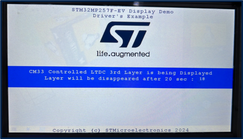
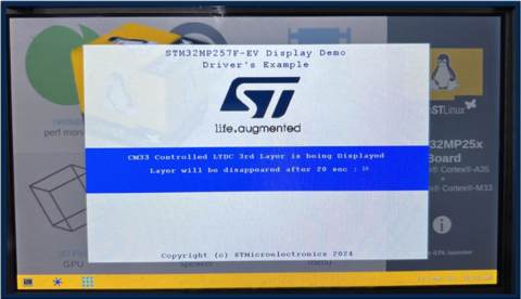
This article aims to specify how to use LTDC 3rd Layer, controlled by Arm®-Cortex® M33 while displaying standard HMI on OpenSTLinux side using STM32Cube MPU firmware example.
This article also explains how to configure LTDC 3rd layer (Resolution, Window sizing, Opacity), how to make changes in OPTEE RIF settings from external-dt so that LTDC Layer can be controlled via Arm®-Cortex® M33.
2. Prerequisites[edit source]
For this use case, required hardware and software stack are listed below:
- The STM32MP257x-EV1 Evaluation board
 (Along with LVDS Full HD display Panel)
 - The STM32CubeMP2 Package - Getting started
3. LTDC 3rd Layer Example Description[edit source]
The goal of this example is to demonstrate Arm®-Cortex® M33 controlled 3rd Layer non-protected while displaying standard HMI on Linux® side.
3.1. Steps to configure the 3rd Layer of LTDC[edit source]
- Read back common registers to determine Panel info (height and width)
- Configure the 3rd Layer with noReload trigger
- Window Sizing (Full Screen and Partial Screen Mode) controlled by "FULLSCREEN" Preprocessor
- Opacity (controlled by constA : set in such a way HMI will be visible)
- Input Pixel Format (Input Pixel Format will be RGB565)
- Set Immediate reload type (reload)
3.2. LTDC 3rd Layer Display Content[edit source]
- Splash screen will be displayed with content (Example description, and ST logo)
- Splash screen will be disappeared after 20 second timeout (SUCCESS)
3.3. Operating mode[edit source]
After LCD initialization, the LCD layer 3 is configured as following:
- FULLSCREEN Mode (with "FULLSCREEN" Preprocessor) layer 3 is configured to display a framebuffer content from DDR with direct color (RGB565) as pixel format and 1024x600 px size.
- Partial Screen Mode (with no "FULLSCREEN" Preprocessor) Layer 3 is configured to display a framebuffer content from DDR with direct color (RGB565) as pixel format and 720x480 px size.
3.4. Display composition[edit source]
LTDC internal peripheral supports 3 Layers of display composition, where blending order and blending factor of each layer with other can be configured. The common register, Layer 1 and Layer 2 configuration is being controlled by CA35 whereas to demonstrate the LTDC 3rd Layer, Layer 3 resource is allocated to Arm®-Cortex® M33,
4. How to configure RIF to use LTDC 3rd layer in a non-secure context from Arm-Cortex M33[edit source]
"ltdc_m33_layer" region of 4M size has been used for framebuffer (fb_address: 0x81300000 of 4MB).
To be able to write via Arm®-Cortex® M33 and read via LTDC AXI DMA engine in NSEC state to this framebuffer region, CID2 and CID4 are listed into read and write list of RISAF region 12
LTDC_L2_ID resource under RIFSC has been statically allocated to CID2 and set to non-secure access
- Refer below changes in the External DT
<EXTERNAL DT>/optee/stm32mp257f-ev1-ca35tdcid-ostl-m33-examples-rif.dtsi
&rifsc {
st,protreg = <
.
.
.
RIFPROT(STM32MP25_RIFSC_LTDC_L0L1_ID, RIF_UNUSED, RIF_UNLOCK, RIF_NSEC, RIF_PRIV, RIF_CID1, RIF_SEM_DIS, RIF_CFEN)
- RIFPROT(STM32MP25_RIFSC_LTDC_L2_ID, RIF_UNUSED, RIF_UNLOCK, RIF_NSEC, RIF_PRIV, RIF_CID1, RIF_SEM_DIS, RIF_CFEN)
+ RIFPROT(STM32MP25_RIFSC_LTDC_L2_ID, RIF_UNUSED, RIF_UNLOCK, RIF_NSEC, RIF_PRIV, RIF_CID2, RIF_SEM_DIS, RIF_CFEN)
RIFPROT(STM32MP25_RIFSC_LTDC_ROT_ID, RIF_UNUSED, RIF_UNLOCK, RIF_NSEC, RIF_PRIV, RIF_CID1, RIF_SEM_DIS, RIF_CFEN)
.
.
.
>;
};
&rifsc {
st,rimu = <
.
.
RIMUPROT(RIMU_ID(9), RIF_UNUSED, RIF_NSEC, RIF_PRIV, RIF_CIDSEL_P)
RIMUPROT(RIMU_ID(10), RIF_UNUSED, RIF_NSEC, RIF_PRIV, RIF_CIDSEL_P)
RIMUPROT(RIMU_ID(11), RIF_CID4, RIF_NSEC, RIF_PRIV, RIF_CIDSEL_M)
- RIMUPROT(RIMU_ID(12), RIF_CID4, RIF_SEC, RIF_PRIV, RIF_CIDSEL_M)
+ RIMUPROT(RIMU_ID(12), RIF_CID4, RIF_NSEC, RIF_PRIV, RIF_CIDSEL_M)
RIMUPROT(RIMU_ID(13), RIF_CID4, RIF_NSEC, RIF_PRIV, RIF_CIDSEL_M)
RIMUPROT(RIMU_ID(14), RIF_UNUSED, RIF_NSEC, RIF_PRIV, RIF_CIDSEL_P)
RIMUPROT(RIMU_ID(15), RIF_UNUSED, RIF_NSEC, RIF_PRIV, RIF_CIDSEL_P)
.
.
>;
};
<dc_m33_layer {
st,protreg = <RISAFPROT(RISAF_REG_ID(12), RIF_CID2_BF|RIF_CID4_BF, RIF_CID2_BF|RIF_CID4_BF, RIF_UNUSED, RIF_NSEC, RIF_ENC_DIS, RIF_BREN_EN)>;
};
&risaf4 {
- memory-region= <&tfm_code>, <&cm33_cube_fw>, <&tfm_data>, <&cm33_cube_data>, <&ipc_shmem>, <&spare1>, <&bl31_context>, <&op_tee>, <&linuxkernel1>, <&gpu_reserved>, <<dc_sec_layer>, <<dc_sec_rotation>, <&linuxkernel2>;
+ memory-region= <&tfm_code>, <&cm33_cube_fw>, <&tfm_data>, <&cm33_cube_data>, <&ipc_shmem>, <&spare1>, <&bl31_context>, <&op_tee>, <&linuxkernel1>, <&gpu_reserved>, <<dc_m33_layer>, <<dc_sec_layer>, <<dc_sec_rotation>, <&linuxkernel2>;
};
<EXTERNAL DT>/optee/stm32mp257f-ev1-ca35tdcid-ostl-m33-examples-resmem.dtsi
reserved-memory {
#address-cells = <2>;
#size-cells = <2>;
ranges;
.
.
.
+ ltdc_sec_rotation: ltdc-sec-rotation@ff000000 {
+ reg = <0x0 0xff000000 0x0 0x1000000>;
+ no-map;
+ };
.
.
}
- Update the OP-TEE external dt refer: How_to_configure_OP-TEE
- Compile OP-TEEImage using How_to_configure_OP-TEE#Build_OP-TEE_OS
- Copy existing FIP binary to <OPTEE>/out/arm-plat-stm32mp2/core
- Command cd <OPTEE>/out/arm-plat-stm32mp2/core
- Command fiptool update fip-stm32mp257f-ev1-ca35tdcid-ostl-m33-examples-optee.bin --tos-fw tee-header_v2.bin --tos-fw-extra1 tee-pager_v2.bin --tos-fw-extra2 tee-pageable_v2.bin
- Copy FIP binary into the target device inside the folder /home/root/
- Run command for microSD card: dd if=fip-stm32mp257f-ev1-ca35tdcid-ostl-m33-examples-optee.bin of=/dev/mmcblk0p5 conv=fdatasync
- where mmcblk0p5 - mmcblk<MMC_INSTANCE>p<FIP_IMAGE_PARTITION_NUM>
- Run command for eMMC: dd if=fip-stm32mp257f-ev1-ca35tdcid-ostl-m33-examples-optee.bin of=/dev/mmcblk1p3 conv=fdatasync
- where mmcblk0p5 - mmcblk<MMC_INSTANCE>p<FIP_IMAGE_PARTITION_NUM>
- Reboot the target device
- Run the example
5. How to run STM32Cube MPU example[edit source]
To run the example on STM32MP257x-EV1 Evaluation board ![]() , perform following steps:
, perform following steps:
- Open STM32CubeIDE
- Build with config: CA35TDCID_m33_ns_sign
- ssh root@192.168.7.1 'mkdir -p /home/root/LTDC_Display_3rdLayer/lib/firmware'
- scp the signed firmware LTDC_Display_3rdLayer_CM33_NonSecure_sign.bin to root@192.168.7.1:/home/root/LTDC_Display_3rdLayer/lib/firmware
- scp the script Firmware/Utilities/scripts/fw_cortex_m33.sh to root@192.168.7.1:/home/root/LTDC_Display_3rdLayer/
- To run the example on target:
On target shell run: - cd /home/root/LTDC_Display_3rdLayer - ./fw_cortex_m33.sh start


