1. Article Purpose[edit source]
The purpose of this article is to: - explain the different lifecycle available on STM32MPU - explain when the will be used - how to manage the transitions.
2. Lifecycle purpose[edit source]
The MPU lifecycle manage the device behavior of some security features during different development phases. It enables some secure mechanisms that are specific on every device family to enforce the security of the system.
3. Lifecycle overview[edit source]
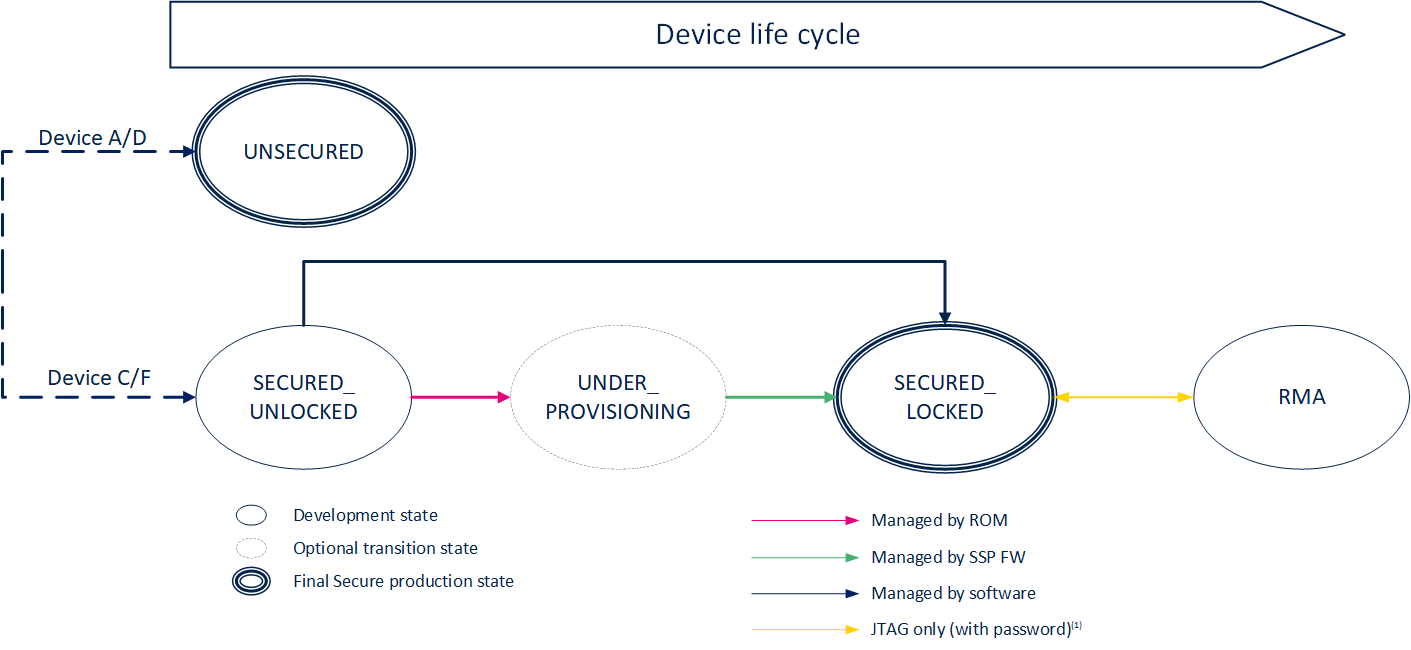
The lifecycle of the STM32 MPU is following the below diagram state:
Each state of the diagram refers implies a specific device behavior:
3.1. Secure Open device[edit source]
In this state, the device is not protected. It is used as an unsecure device usage. It allows to use unsigned firmware for booting. This state is the final state for
All OTP are available for usage.
On STM32MP13xC/F lines ![]() , STM32MP15xC/F lines
, STM32MP15xC/F lines ![]() , STM32MP25xC/F lines
, STM32MP25xC/F lines ![]() , it is possible to evaluate the secure features without locking the device.
, it is possible to evaluate the secure features without locking the device.
3.2. Secure Provisioning[edit source]
The Secure provisioning state is a specific state where the device is only limited to execute the SSP) use case.
In this state, the device certificate is generated and can be exported. All the OTP are available for provisioning. As soon as the SSP process is done, the SSP firmware will directly set the lifecycle to the next state.
3.3. Secure Closed device[edit source]
This state is a final secure state. Once the device achieve this state, all the hardware secure mechanism are enabled:
- Secure boot is enabled: The first booted images must be signed with the provisioned keys.
- Isolation mechanism are in place and must be guarantee to guarantee the low power mechanism:
- Backup registers security is enforced.
- Peripheral assignment.
3.4. RMA[edit source]
RMA is a specific analysis state where it becomes possible to debug device issues. It is protected by a password and required a specific processing to enter in this state describe in AN5827. It ensure that all the secrets stored in the Upper OTP are no more accessible (including the hardware unique key usage).
The switch between RMA and Secure closed device state is limited by a counter:
4. Encoding lifecycle[edit source]
The lifecycle uses a set of OTP words to encode the different states.
4.1. STM32MP13x lines  [edit source]
| Secure Open device | |
|---|---|
| OTP Word | Value |
| 0 - Bit [6:0] | 0000010111 |
| Secure Provisioning | |
| OTP Word | Value |
| 0 - Bit [6-0] | 0000111111 |
| 9 - Bit [5] | 1 |
| Secure Close device | |
| OTP Word | Value |
| 0 - Bit [6:0] | 0000111111 |
| 9 - Bit [6:5] | 11 (In case of SSP) |
4.2. STM32MP15x lines  [edit source]
| Secure Open device | |
|---|---|
| OTP Word | Value |
| 0 - Bit [6:0] | 01x1xxx / 01x1xxx / 0xx11xx / 01xxxx1 |
| Secure Provisioning | |
| 0 - Bit [6:0] | 01x1xxx / 01x1xxx / 0xx11xx / 01xxxx1 |
| 8 - Bit [8] | 1 |
| Secure Close device | |
| OTP Word | Value |
| 0 - Bit [6:0] | 1xxx1x1 / 11x1xxx / 1xx11xx / 11xxxx1 |
| 8 - Bit [9:8] | 11 (In case of SSP) |
4.3. STM32MP25x lines  [edit source]
| Secure Open device | |
|---|---|
| OTP Word | Value |
| 0 | 0xaaaa5555 |
| 1 | 0x000000ff |
| Secure Provisioning | |
| OTP Word | Value |
| 0 | 0xaaaa5555 |
| 1 | 0x000000ff |
| 18 - Bit[3:0] | xx1/x1x/1xx |
| Secure Close device | |
| OTP Word | Value |
| 0 | 0xaaaa5555 |
| 1 | 0x000000ff |
| 18 - Bit[3:0] | xx1/x1x/1xx |
| 18 - Bit[7:4] | xxx1/xx1x/x1xx/1xxx |
5. References[edit source]
