1. Article purpose[edit source]
This article aims to specify how to use LTDC 3rd Layer, controlled by Arm®-Cortex® M33 while displaying standard HMI on Linux® side using STM32Cube MPU firmware example.
This article also explains how to configure LTDC 3rd layer (Resolution, Window sizing, Opacity), how to make changes in OPTEE RIF settings from external-dt so that LTDC Layer can be controlled via Arm®-Cortex® M33.
2. Prerequisites[edit source]
For this use case, required hardware and software stack are listed below:
- The STM32MP257x-EV1 Evaluation board
 (Along with LVDS Full HD display Panel)
 - The STM32CubeMP2 Package
3. LTDC 3rd Layer Example Description[edit source]
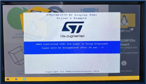
The goal of this example is to demonstrate Arm®-Cortex® M33 controlled 3rd Layer non-protected while displaying standard HMI on Linux® side.
3.1. Steps to configure the 3rd Layer of LTDC[edit source]
- Read back common registers to determine Panel info (height and width)
- Configure the 3rd Layer with noReload trigger
- Window Sizing (Full Screen and Partial Screen Mode) controlled by "FULLSCREEN" Preprocessor
- Opacity (controlled by constA : set in such a way HMI will be visible)
- Input Pixel Format (Input Pixel Format will be RGB565)
- Set Immediate reload type (reload)
3.2. LTDC 3rd Layer Display Content[edit source]
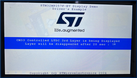
- Splash screen will be displayed with content (Example description, and ST logo)
- Splash screen will be disappeared after 20 second timeout (SUCCESS)
3.3. Operating Mode[edit source]
After LCD initialization, the LCD layer 3 is configured as following:
- FULLSCREEN Mode (with "FULLSCREEN" Preprocessor) layer 3 is configured to display a framebuffer content from DDR with direct color (RGB565) as pixel format and 1024x600 px size.
- Partial Screen Mode (with no "FULLSCREEN" Preprocessor) Layer 3 is configured to display a framebuffer content from DDR with direct color (RGB565) as pixel format and 720x480 px size.
3.4. Display composition[edit source]
LTDC internal peripheral supports 3 Layers of display composition, where blending order and blending factor of each layer with other can be configured. The common register, Layer 1 and Layer 2 configuration is being controlled by CA35 whereas to demonstrate the LTDC 3rd Layer, Layer 3 resource is allocated to Arm®-Cortex® M33,
4. How to configure RIF to use LTDC 3rd layer in a non-secure context from Arm-Cortex M33[edit source]
"ltdc_m33_layer" region of 4M size has been used for framebuffer (fb_address: 0x81300000 of 4MB).
To be able to write via Arm®-Cortex® M33 and read via LTDC AXI DMA engine in NSEC state to this framebuffer region, CID2 and CID4 are listed into read and write list of RISAF region 12
LTDC_L2_ID resource under RIFSC has been statically allocated to CID2 and set to non-secure access
- Refer below changes in the External DT
<EXTERNAL DT>/optee/stm32mp257f-ev1-ca35tdcid-ostl-m33-examples-rif.dtsi
&rifsc {
st,protreg = <
.
.
.
RIFPROT(STM32MP25_RIFSC_LTDC_L0L1_ID, RIF_UNUSED, RIF_UNLOCK, RIF_NSEC, RIF_PRIV, RIF_CID1, RIF_SEM_DIS, RIF_CFEN)
- RIFPROT(STM32MP25_RIFSC_LTDC_L2_ID, RIF_UNUSED, RIF_UNLOCK, RIF_NSEC, RIF_PRIV, RIF_CID1, RIF_SEM_DIS, RIF_CFEN)
+ RIFPROT(STM32MP25_RIFSC_LTDC_L2_ID, RIF_UNUSED, RIF_UNLOCK, RIF_NSEC, RIF_PRIV, RIF_CID2, RIF_SEM_DIS, RIF_CFEN)
RIFPROT(STM32MP25_RIFSC_LTDC_ROT_ID, RIF_UNUSED, RIF_UNLOCK, RIF_NSEC, RIF_PRIV, RIF_CID1, RIF_SEM_DIS, RIF_CFEN)
.
.
.
>;
};
&rifsc {
st,rimu = <
.
.
RIMUPROT(RIMU_ID(9), RIF_UNUSED, RIF_NSEC, RIF_PRIV, RIF_CIDSEL_P)
RIMUPROT(RIMU_ID(10), RIF_UNUSED, RIF_NSEC, RIF_PRIV, RIF_CIDSEL_P)
RIMUPROT(RIMU_ID(11), RIF_CID4, RIF_NSEC, RIF_PRIV, RIF_CIDSEL_M)
- RIMUPROT(RIMU_ID(12), RIF_CID4, RIF_SEC, RIF_PRIV, RIF_CIDSEL_M)
+ RIMUPROT(RIMU_ID(12), RIF_CID4, RIF_NSEC, RIF_PRIV, RIF_CIDSEL_M)
RIMUPROT(RIMU_ID(13), RIF_CID4, RIF_NSEC, RIF_PRIV, RIF_CIDSEL_M)
RIMUPROT(RIMU_ID(14), RIF_UNUSED, RIF_NSEC, RIF_PRIV, RIF_CIDSEL_P)
RIMUPROT(RIMU_ID(15), RIF_UNUSED, RIF_NSEC, RIF_PRIV, RIF_CIDSEL_P)
.
.
>;
};
<dc_m33_layer {
st,protreg = <RISAFPROT(RISAF_REG_ID(12), RIF_CID2_BF|RIF_CID4_BF, RIF_CID2_BF|RIF_CID4_BF, RIF_UNUSED, RIF_NSEC, RIF_ENC_DIS, RIF_BREN_EN)>;
};
&risaf4 {
- memory-region= <&tfm_code>, <&cm33_cube_fw>, <&tfm_data>, <&cm33_cube_data>, <&ipc_shmem>, <&spare1>, <&bl31_context>, <&op_tee>, <&linuxkernel1>, <&gpu_reserved>, <<dc_sec_layer>, <<dc_sec_rotation>, <&linuxkernel2>;
+ memory-region= <&tfm_code>, <&cm33_cube_fw>, <&tfm_data>, <&cm33_cube_data>, <&ipc_shmem>, <&spare1>, <&bl31_context>, <&op_tee>, <&linuxkernel1>, <&gpu_reserved>, <<dc_m33_layer>, <<dc_sec_layer>, <<dc_sec_rotation>, <&linuxkernel2>;
};
<EXTERNAL DT>/optee/stm32mp257f-ev1-ca35tdcid-ostl-m33-examples-resmem.dtsi
reserved-memory {
#address-cells = <2>;
#size-cells = <2>;
ranges;
.
.
.
+ ltdc_sec_rotation: ltdc-sec-rotation@ff000000 {
+ reg = <0x0 0xff000000 0x0 0x1000000>;
+ no-map;
+ };
.
.
}
- Update the OP-TEE external dt refer: How_to_configure_OP-TEE
- Compile OP-TEEImage using How_to_configure_OP-TEE#Build_OP-TEE_OS
- Copy existing FIP binary to <OPTEE>/out/arm-plat-stm32mp2/core
- Command cd <OPTEE>/out/arm-plat-stm32mp2/core
- Command fiptool update fip-stm32mp257f-ev1-ca35tdcid-ostl-m33-examples-optee.bin --tos-fw tee-header_v2.bin --tos-fw-extra1 tee-pager_v2.bin --tos-fw-extra2 tee-pageable_v2.bin
- Copy FIP binary into the target device inside the folder /home/root/
- Run command for microSD card: dd if=fip-stm32mp257f-ev1-ca35tdcid-ostl-m33-examples-optee.bin of=/dev/mmcblk0p5 conv=fdatasync
- where mmcblk0p5 - mmcblk<MMC_INSTANCE>p<FIP_IMAGE_PARTITION_NUM>
- Run command for eMMC: dd if=fip-stm32mp257f-ev1-ca35tdcid-ostl-m33-examples-optee.bin of=/dev/mmcblk1p3 conv=fdatasync
- where mmcblk0p5 - mmcblk<MMC_INSTANCE>p<FIP_IMAGE_PARTITION_NUM>
- Reboot the target device
- Run the example
5. How to run STM32Cube MPU example[edit source]
To run the example on STM32MP257x-EV1 Evaluation board ![]() , perform following steps:
, perform following steps:
- Open STM32CubeIDE
- Build with config: CA35TDCID_m33_ns_sign
- ssh root@192.168.7.1 'mkdir -p /home/root/LTDC_Display_3rdLayer/lib/firmware'
- scp the signed firmware LTDC_Display_3rdLayer_CM33_NonSecure_sign.bin to root@192.168.7.1:/home/root/LTDC_Display_3rdLayer/lib/firmware
- scp the script Firmware/Utilities/scripts/fw_cortex_m33.sh to root@192.168.7.1:/home/root/LTDC_Display_3rdLayer/
- To run the example on target:
On target shell run: - cd /home/root/LTDC_Display_3rdLayer - ./fw_cortex_m33.sh start


