1. Purpose[edit source]
This article proposes some guidelines in order to determine the best low power strategy for your STM32MP15 product.
2. STM32MP15 main power supplies and low power modes[edit source]
For a good understanding of this article, it is important to understand the perimeter of the two STM32MP15 main power supplies:
- VDD supplies I/Os and system analog such as reset, power management, oscillators and PLLs. VDD is present as far as the STM32MP15 is not in OFF or VBAT mode. For a given system, its voltage is fixed and chosen in the range from 1.8 V to 3.3 V supported by the STM32MP1 Series.
- VDDcore supplies the digital core domain and must be present after VDD on start up. Its voltage varies depending on the system state:
- 1.2 V typical in Run and (LP-)Stop modes
- 0.9 V typical in LPLV-Stop mode
- OFF in Standby mode
For more information, please refer to the PWR chapter of the STM32MP15 Reference Manual.
3. STM32MP15 low power modes overview[edit source]
When the system does not need to run for a while, various actions can be taken to reduce its power consumption:
- Stop the clocks: this corresponds to the Stop mode and the external regulator can even be allowed to switch in low power mode in order to reduce its power consumption: this is the LP-Stop mode.
- Reduce the supply voltage
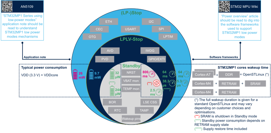
4. STM32MP15 low power modes overview[edit source]
For each supported low power mode (described in the AN5109), the figure below shows:
- The peripherals that can be used as wake up sources (in grey boxes)
- The STM32MP15 typical power consumption (on the left)
- The system wake up times in various configurations (on the right)