This article shows how to start up a STM32MP257x-EV1 ![]() Evaluation boards (high-end development platforms for the STM32MP25 microprocessor devices). It is valid for the STM32MP257F-EV1
Evaluation boards (high-end development platforms for the STM32MP25 microprocessor devices). It is valid for the STM32MP257F-EV1 ![]() Evaluation boards: the part numbers are specified in the STM32MP25 microprocessor part numbers article.
Evaluation boards: the part numbers are specified in the STM32MP25 microprocessor part numbers article.
It lists the required material, points to the board features description, and gives the step-by-step process to set up the system.
Finally, it proposes to run some basic use cases and to discover some of the board capabilities.
1. Starter Package content[edit source]
This Starter Package provides:
- the OpenSTDroid distribution binaries
- the partition layout required to flash the device with STM32CubeProgrammer
2. Checking the material[edit source]
Mandatory
| PC | Linux or Windows operating systems. See PC prerequisites for more details on the required configurations |
| STM32MP257x-EV1 Evaluation board | High-end development platform for the STM32MP25 microprocessor device including:
|
| microSDTM card | It is populated with OpenSTLinux distribution (Linux software), and provides extra storage capacity. A 8-Gbyte minimum MicroSD card is needed |
| USB type-C cable | It connects the STM32MP257x-EV1 Evaluation board to the PC through the USB type-C (ST-LINK/V3) connector |
| USB type-C cable | It connects the STM32MP257x-EV1 Evaluation board to an USB OTG device through the USB micro-AB connector |
Optional
| LCD screen | Several types of screen are possible : LVDS, DSI or HDMI |
| Power supply | (Optional) Power supply block (5V, 3A) for the MB1936 board. |
| USB keyboard and mouse | Thanks to the USB type A connectors, the STM32MP257x-EV1 Evaluation board can be equipped with a full-size keyboard and mouse |
| Ethernet cable | It can connect the STM32MP257x-EV1 Evaluation board to a network through the RJ45 connector |
| RS232 cable | It can connect the STM32MP257x-EV1 Evaluation board to the PC through the UART connector as an alternative of the ST-LINK/V2-1 connection |
| CAN cable | It can connect the STM32MP257x-EV1 Evaluation board to CAN devices through the CAN FD/TT connectors |
| Trace cable | It can connect the STM32MP257x-EV1 Evaluation board to an external tool through the Trace connector |
| JTAG cable | It can connect the STM32MP257x-EV1 Evaluation board to an external tool through the JTAG connector |
Optionally, devices and extension boards might be plugged to the STM32MP257x-EV1 Evaluation board thanks to connectors such as:
- the GPIO expansion connector
- the PCIe connector
- the Mikro bus connector
- ...
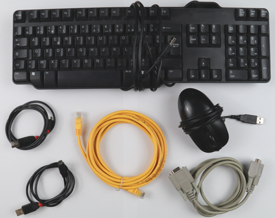
The following figure shows the material not included in STM32MP25 Evaluation board package, that is used in this Starter Package.
3. Assembling the board[edit source]
The STM32MP257x-EV1 Evaluation boards packages (STM32MP257F-EV1 ![]() ), completed by the B-CAMS-IMX package, include all the items listed below.
), completed by the B-CAMS-IMX package, include all the items listed below.
")
| Position | Description |
|---|---|
| 1 | MB1936 main board |
| 2 | 7” LVDS WSVGA display with touch panel (EDT ETML0700Z9NDHA panel - optional) |
| 3 | LVDS display cable |
| 4 | MB1854 board AI camera (not part of STM32MP257x-EV1 Evaluation boards packages , provided via B-CAMS-IMX package) |
| 5 | camera board FFC (not part of STM32MP257x-EV1 Evaluation boards packages, provided via B-CAMS-IMX package) - optional |
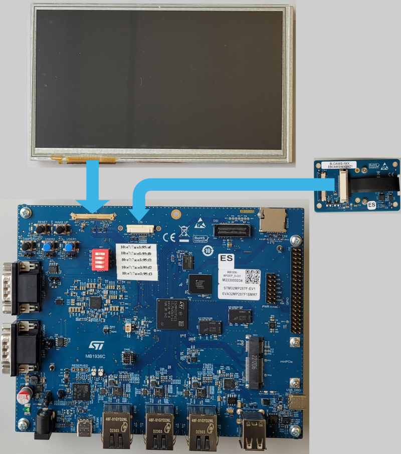
3.1. How to connect LVDS display to MB1936[edit source]
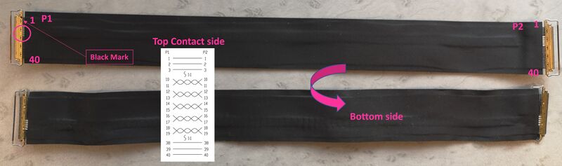
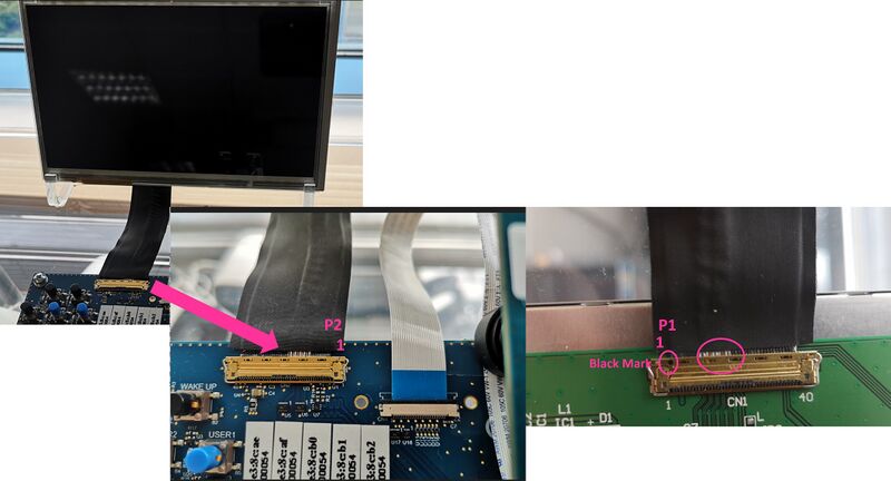
- Check the above cable orientation thanks to the black mark and the white twisted pairs.
- Find the LVDS port on STM32MP257x-EV1 Evaluation board (CN2) and the one on the display (CN1). One cable is provided in the STM32MP257x-EV1 Evaluation board box.
- On each port, insert the cable as described:
3.2. STM32MP257x-EV1 Evaluation board assembled[edit source]

4. Installing the tools[edit source]
4.1. Installing the STM32CubeProgrammer tool[edit source]
| STM32CubeProgrammer for Linux® host PC | STM32CubeProgrammer for Windows® host PC | |
|---|---|---|
| Download |
Version v2.17.0
| |
| Installation |
$> ./SetupSTM32CubeProgrammer-2.17.0.linux
$> export PATH=<my STM32CubeProgrammer install directory>/bin:$PATH
$> ln -s <my STM32CubeProgrammer install directory>/bin/STM32_Programmer_CLI /home/bin/STM32_Programmer_CLI |
|
| User manual |
| |
| Detailed release note |
| |
4.2. Preparing the USB serial link for flashing[edit source]
It is recommended to use the USB (in DFU mode) for flashing rather than the UART, which is too slow.
Below indications on how to install the USB in DFU mode under Linux and Windows OS, respectively.
- For Linux host PC or Windows host PC with VMWare:
The libusb1.0 package (including USB DFU mode) must be installed to be able to connect to the board via the USB port. This is achieved by typing the following command from the host PC terminal:
sudo apt-get install libusb-1.0-0
To allow STM32CubeProgrammer to access the USB port through low-level commands, proceed as follows:
 cd <your STM32CubeProgrammer install directory>/Drivers/rules

 sudo cp *.* /etc/udev/rules.d/
- For Windows host PC:
Run the “STM32 Bootloader.bat” file to install the STM32CubeProgrammer DFU driver and activate the STM32 microprocessor device in USB DFU mode. This driver (installed by STM32 Bootloader.bat) is provided within the STM32CubeProgrammer release package. It is located in the DFU driver folder, \Drivers\DFU_Driver.
In case of issue, refer to How to proceed when the DFU driver installation fails on Windows host PC.
To validate the installation, the DFU driver functionality can be verified by following the FAQ instructions provided in how to check if the DFU driver is functional.
5. Downloading the image and flashing it on the board[edit source]
5.1. Image download[edit source]
The software package is provided AS IS, and by downloading it, you agree to be bound to the terms of the software license agreement (SLA0048). The detailed content licenses can be found here.
| STM32MPU distribution for Android™ | |||
| Tag | Flash device | Link | Release note |
| st-android-13.0.0-2024-04-05 | hybrid (eMMC / microSD card) | st-android-13.0.0-2024-04-05-stm32mp257f-ev1-emmc-starter.tar.gz | st-android-13.0.0-2024-04-05 release note |
5.2. Flashing the eMMC images[edit source]
The STM32CubeProgrammer tool is used to flash the STM32MP25 Evaluation board with the downloaded image.
Several Flash devices (microSD, eMMC...) are available on this board: see the STM32 MPU Flash mapping for Android article if you want to know more about the supported Flash memory technologies, and the Flash partitions. The steps below consider the eMMC as the Flash device.
As explained in the boot chain overview, the optee boot chain is the default solution delivered by STMicroelectronics. Thus, the steps below use the image for the optee boot chain.
Let's flash the downloaded image on the eMMC card:
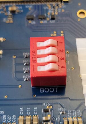
- Set the boot switches to the off position (boot from UART/USB)
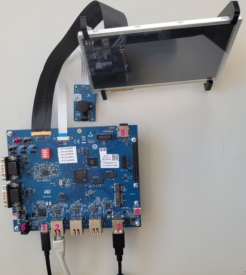
- Connect the USB type-C (OTG) port (4) to the host PC that contains the downloaded image
- Insert the delivered microSD card into the dedicated slot (5)
- Connect the USB type-C (power supply) port (1) to the power connector or a host PC (and check the power jumper position)
- Press the reset button (7) to reset the board
- Go to the Starter Package directory that contains the binaries and the Flash layout files
cd <Starter Package installation directory>/stm32mp2-openstlinux-6.1-yocto-mickledore-mpu-v24.06.26/images/stm32mp2
If you have followed the the proposition to organize the working directory, the command is
 cd Starter-Package/stm32mp2-openstlinux-6.1-yocto-mickledore-mpu-v24.06.26/images/stm32mp2
- Check that the STM32CubeProgrammer tool is installed and accessible; if not, go to the installation procedure (installing the tools)
 STM32_Programmer_CLI --h
      -------------------------------------------------------------------
                        STM32CubeProgrammer <tool version>
      -------------------------------------------------------------------
- Get the device port location for the USB link
STM32_Programmer_CLI -l usb
       -------------------------------------------------------------------
                         STM32CubeProgrammer <tool version>
       -------------------------------------------------------------------

=====  DFU Interface   =====

Total number of available STM32 device in DFU mode: 1

  Device Index           : USB1
  USB Bus Number         : 003
  USB Address Number     : 002
  Product ID             : DFU in HS Mode @Device ID /0x505, @Revision ID /0x100
  Serial number          : 003A00423836500B00343046
  Firmware version       : 0x0110
  Device ID              : 0x0505
- Flash the eMMC with the image for the trusted boot chain
STM32_Programmer_CLI -c port=usb1 -w flashlayout_st-image-weston/optee/FlashLayout_emmc_optee.tsv
This operation takes several minutes.
Go see the STM32CubeProgrammer article to know more about the flashing operation
5.3. Flashing the data raw image - case hybrid[edit source]
In case of the starter is an hybrid (eMMC / microSD card) package, you have to flash the data raw image in the microSD card.
On a Linux machine (ex: Ubuntu), you can execute the following commands :
 dd if=st-android-optee-sd.raw of=<microSD destination> bs=8M conv=fdatasync status=progress
 sgdisk --move-second-header <microSD destination>
On a Windows machine, you can use a tool as the HDD Raw Copy Tool:
- Select the SOURCE: st-android-optee-sd.raw
- Select the TARGET: microSD card
- Click on “START” button
6. How to go further?[edit source]
Now that the image is flashed on the STM32MP25 Evaluation board, you might want to switch to the STM32MPU Distribution Package for Android, in order to modify or tune the STM32MPU Embedded Software distribution with your own developments.