The STM32CubeMP2 Package is part of the STM32 MPU embedded software offer. It runs on the Arm® Cortex®-M33 coprocessor.
It is included in the three software packages proposed by the Linux® Yocto-based embedded software:
- in the starter package as pre-built examples (firmware),
- in the developer package as full source code for development (associated with an IDE),
- in the distribution package as a dedicated recipe (that integrates the full source code) in the OpenSTLinux distribution.
Therefore, this article explains how to develop, build and run existing or new examples thanks to these three software packages.
1. Prerequisites[edit source]
In the next chapters, it is assumed that the selected board is assembled according to the information provided in its hardware description article (e.g., STM32MP257x-EV1 - hardware description for STM32MP257x-EV1 Evaluation boards), and that the different boot related switches of the board are also known (e.g., boot related switches for STM32MP257x-EV1 Evaluation boards).
Refer also to the Which Package better suits your needs article for further information on all packages.
The firmware is loaded into the Arm® Cortex®-M33 coprocessor by the Arm® Cortex®-A35 processor running the Linux® distribution making use of the Linux Remote Proc framework. This method is also referred to as Production Mode
- Refer to Coprocessor_management_overview article to get an overview of mechanisms to put in place to design software in the multiprocessor system.
2. Starter Package for STM32CubeMP2[edit source]
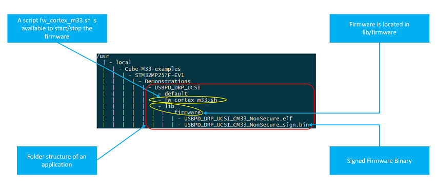
The Linux Yocto-based starter packages (STM32MP25 Evaluation boards - Starter_Package) contain pre-built examples (firmware) that are located in the Linux file system (userfs folder: /usr/local/Cube-M33-examples/<board_name>/Examples), and that be run from a host console thanks to a dedicated script (fw_cortex_m33.sh).
This chapter, and its sub-chapters, aims to explain all steps needed to run an existing example.
2.1. Starter Package prerequisites[edit source]
Refer to the Starter Package for STM32MP25 Eval Board for all the information describing how to install the Starter Package.
2.2. User file system for Arm® Cortex®-M33 examples[edit source]
The folder structure of Linux User File System for STM32Cube M33 firmware is described below for STM32MP257F-EV1 board:
2.3. Demonstration Cube FW application running out of the box[edit source]
- Use the starter package and flash images onto your board. You need to open a Linux console (Refer to How to get Terminal) to interact with the system over command line interface.
- With the default images provided with the distribution you would have a demonstration project running the USBPD firmware on the Cortex®-M33 coprocessor when system boots up.
- Learn more about the demonstration project here : Readme
If you want to run other examples and applications on Cortex®-M33 coprocessor you should Jump to Developer Package for STM32CubeMP2.
3. Developer Package for STM32CubeMP2[edit source]
The STM32MPU Developer Package article explains how to get the source code for the STM32CubeMP2 Package, and the associated tools (e.g., IDE).
This chapter and its sub-chapters aim to explain all steps needed to run an existing example using STM32CubeIDE. Once done, you can jump to the chapter #How to go further with the Developer Package to enhance your experience with the STM32CubeMP2 Developer Package.
3.1. Developer Package prerequisites[edit source]
- Refer to the Installing the STM32CubeMP2 Package to obtain and install the source code
- Refer to the new recommended IDE: STM32CubeIDE
- Make sure that you install the images using the FlashLayout_<boot_storage>_<board_name>-ca35tdcid-ostl-m33-examples-optee.tsv file. This is required as peripherals used by M33 have been assigned to M33 in RIF config.
3.2. How to build and run an existing example with the Eclipse IDE[edit source]
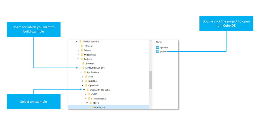
- Open the Projects Folder containing the example and double-click on file .project to open Eclipse IDE:
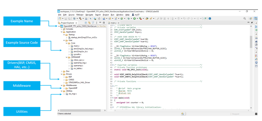
- Below figure explains a typical layout of a cube firmware project developed with STM32CubeIDE
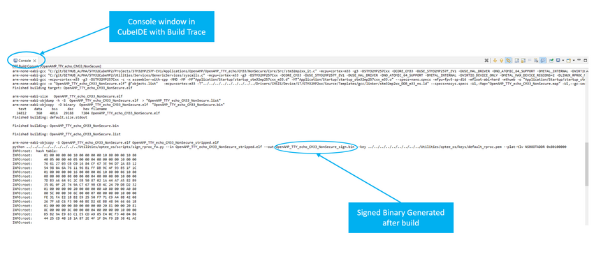
- Select a config and press hammer button to build the example
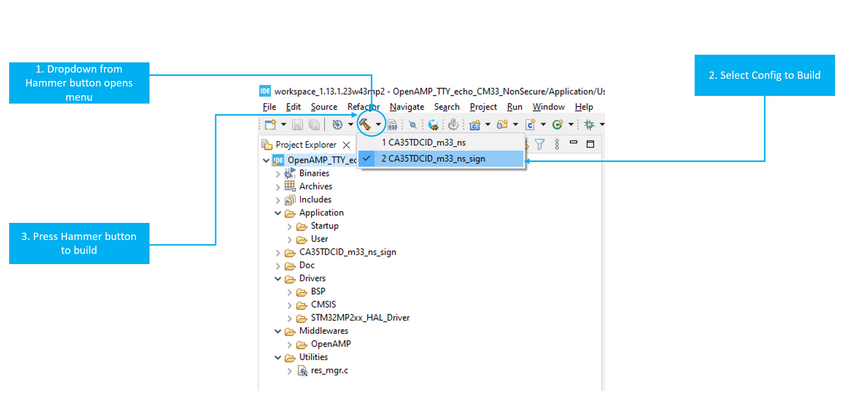
- Firmware binaries must be signed before they can be executed on the co-processor.
3.3. How to run examples[edit source]
- After you have built the signed firmware binary as shown in the previous section, it should be copied and executed on the Coprocessor.
3.3.1. Copy built firmware to correct directory in the target filesystem (STM32 board)[edit source]
- When system boots from flash (production mode), the USB port can be connected to your host machine and it would appear as a device with IP address: 192.168.7.1
- From a GitBash Shell (On Windows) or Terminal Windows (on a Linux machine) of your host PC, run the following commands to copy the Firmware on to the target.
 $ ssh root@192.168.7.1 'mkdir -p /usr/local/Cube-M33-examples/STM32MP257F-EV1/Applications/OpenAMP_TTY_echo/lib/firmware'
 $ scp Projects/STM32MP257F-EV1/Applications/OpenAMP/OpenAMP_TTY_echo/STM32CubeIDE/CM33/NonSecure/CA35TDCID_m33_ns_sign/OpenAMP_TTY_echo_CM33_NonSecure_sign.bin root@192.168.7.1:/usr/local/Cube-M33-examples/STM32MP257F-EV1/Applications/OpenAMP_TTY_echo/lib/firmware/
 $ scp Utilities/scripts/fw_cortex_m33.sh  root@192.168.7.1:/usr/local/Cube-M33-examples/STM32MP257F-EV1/Applications/OpenAMP_TTY_echo/
- Above commands assume that the project is an Application and its name is OpenAMP_TTY_echo, you can replace these strings with your project type(Examples or Applications) and the corresponding name.
3.3.2. Starting the example firmware[edit source]
- Once copied to the target, the firmware can be run by executing the script as follows:
  cd /usr/local/Cube-M33-examples/STM32MP257F-EV1/Applications/OpenAMP_TTY_echo/
   ./fw_cortex_m33.sh start
 fw_cortex_m33.sh: fmw_name=OpenAMP_TTY_echo_CM33_NonSecure_sign.bin
 Stopping running fw ...
 [ 1232.784799] remoteproc remoteproc0: stopped remote processor m33
 [ 1232.795058] remoteproc remoteproc0: powering up m33
 [ 1232.801334] remoteproc remoteproc0: Booting fw image OpenAMP_TTY_echo_CM33_NonSecure_sign.bin, size 34440
 [ 1232.806431] rproc-virtio rproc-virtio.10.auto: assigned reserved memory node vdev0buffer@812fa000
 [ 1232.815436] virtio_rpmsg_bus virtio0: rpmsg host is online
 [ 1232.820030] rproc-virtio rproc-virtio.10.auto: registered virtio0 (type 7)
 [ 1232.826673] remoteproc remoteproc0: remote processor m33 is now up
 [ 1232.833005] virtio_rpmsg_bus virtio0: creating channel rpmsg-tty addr 0x400
 [ 1232.840724] virtio_rpmsg_bus virtio0: creating channel rpmsg-tty addr 0x401
3.3.3. Stopping the example firmware[edit source]
  cd /usr/local/Cube-M33-examples/STM32MP257F-EV1/Applications/OpenAMP_TTY_echo/
   ./fw_cortex_m33.sh stop
 [ 2290.481170] remoteproc remoteproc0: warning: remote FW shutdown without ack
 [ 2290.482719] remoteproc remoteproc0: stopped remote processor m33
 [2]+  Done                       cat /dev/ttyRPMSG1
 [1]+  Done                       cat /dev/ttyRPMSG0
3.4. How to go further with the Developer Package[edit source]
3.4.1. How to develop on Arm® Cortex®-M33[edit source]
Refer to Getting_started/STM32MP2_boards/STM32MP257x-EV1/Develop_on_Arm®_Cortex®-M33
3.4.1.1. Create your project for your board[edit source]
A project is board and application specific. To create a new project, you may start from any available project from Examples or Applications
All Examples have following characteristics:
- It contains the source code of HAL, CMSIS and BSP drivers which are the minimum components required to develop a code for a given board.
- It contains the include paths for all the firmware components.
- It defines the STM32MP25 supported device, which defines the CMSIS and HAL driver configuration settings.
- It provides pre-configured user files which are ready-to-use as shown below:
- HAL initialized with default time base with ARM Core SysTick.
- SysTick ISR implemented for delay management purpose (HAL_Delay()).
3.4.1.2. Add middleware to your project (optional)[edit source]
Your project may need to support additional middleware. This support is available from these middleware stacks: OpenAMP and AzureRTOS.
Refer to the documentation to understand which middleware source files have to be used.
If you have the experience, it is also possible to look in the application source code to find out which source files and which include paths must be added.
- Applications for board STM32MP257F-EV1 : Projects/STM32MP257F-EV1/Applications
3.4.1.3. Configure the firmware components[edit source]
The HAL and middleware components offer a set of build time configuration options using macros #define, declared in a header file. A template configuration file is provided for each component. It has to be copied to the project folder (usually the configuration file is named xxx_conf_template.h, and the word ‘_template’ needs to be removed when copying it to the project folder).
The configuration file provides enough information to understand the impact of each configuration option. More detailed information is available in the documentation provided with each component.
3.4.1.4. Start the HAL Library[edit source]
After jumping to the main program, the application code must call the function HAL_Init() to initialize the HAL Library. It includes the following tasks:
a) Configuration of the SysTick to generate an interrupt every 1 millisecond with the SysTick interrupt priority TICK_INT_PRIO defined in the file stm32mp2xx_hal_conf.h.
- In production mode, the SysTick clock is already configured by FSBL running on Arm® Cortex®-A35.
b) Set NVIC Group Priority to 0.
c) Call to the HAL_MspInit() function defined in the stm32mp2xx_hal_msp.c user file performs global low-level hardware initializations like HSEM clock enable.
3.4.1.5. Initialize the peripheral[edit source]
a) Edit the file stm32mp2xx_hal_msp.c to write to the peripheral HAL_PPP_MspInit() function. Proceed as follows:
- Enable the peripheral clock.
- Configure the peripheral GPIOs.
- Configure the DMA channel and enable DMA interrupt (if needed).
- Enable peripheral interrupt (if needed).
b) Edit the stm32xxx_it.c file to call on the required interrupt handlers (peripheral and DMA), if needed.
c) Write process complete callback functions if you plan to use peripheral interrupt or DMA.
d) In the main.c file, initialize the peripheral handler structure then call the function HAL_PPP_Init() to initialize your peripheral.
3.4.1.6. Develop your application[edit source]
At this stage, your system is ready and you can start developing your application code.
- The HAL provides intuitive and ready-to-use APIs to configure the peripheral. It supports polling, interrupts and a DMA programming model, to accommodate any application requirement.
- For more details on how to use each peripheral and how to manage real-time constraints, refer to the full set of examples and applications provided in the STM32CubeMP2 Package (List of available projects)
3.4.2. How to tweak RIF settings for your projects=[edit source]
3.4.3. How to configure RIF to use SNOR in a non-secure context from Cortex-M33[edit source]
This section shows how you can share the hardware resources between Cortex-A and Cortex-M by configuring RIF (Resource Isolation Framework) settings.
- Sample Application: Fx_NoR_Write_Read_File
- By default, OCTOSPI2 instance and IOM are inaccessible from Cortex-M33 non-secure context. To allow this access we need to update the RIF settings in OPTEE.
- Update the Optee external dt refer: How_to_configure_OP-TEE#OSTL_device_tree_for_STM32MP2_series
- Make below changes in the file: stm32mp257f-ev1-ca35tdcid-ostl-m33-examples-rif.dtsi
<EXTERNAL DT>/optee/stm32mp257f-ev1-ca35tdcid-ostl-m33-examples-rif.dtsi

 &gpiod {
       st,protreg = <
-              RIFPROT(RIF_IOPORT_PIN(0), RIF_UNUSED, RIF_UNLOCK, RIF_SEC, RIF_PRIV, RIF_CID1, RIF_SEM_DIS, RIF_CFEN)
+              RIFPROT(RIF_IOPORT_PIN(0), RIF_UNUSED, RIF_UNLOCK, RIF_NSEC, RIF_PRIV, RIF_CID2, RIF_SEM_DIS, RIF_CFEN)
              RIFPROT(RIF_IOPORT_PIN(1), RIF_UNUSED, RIF_UNLOCK, RIF_NSEC, RIF_PRIV, RIF_CID1, RIF_SEM_DIS, RIF_CFEN)
              RIFPROT(RIF_IOPORT_PIN(2), RIF_UNUSED, RIF_UNLOCK, RIF_NSEC, RIF_PRIV, RIF_CID1, RIF_SEM_DIS, RIF_CFEN)
-              RIFPROT(RIF_IOPORT_PIN(3), RIF_UNUSED, RIF_UNLOCK, RIF_SEC, RIF_PRIV, RIF_CID1, RIF_SEM_DIS, RIF_CFEN)
-              RIFPROT(RIF_IOPORT_PIN(4), RIF_UNUSED, RIF_UNLOCK, RIF_SEC, RIF_PRIV, RIF_CID1, RIF_SEM_DIS, RIF_CFEN)
-              RIFPROT(RIF_IOPORT_PIN(5), RIF_UNUSED, RIF_UNLOCK, RIF_SEC, RIF_PRIV, RIF_CID1, RIF_SEM_DIS, RIF_CFEN)
-              RIFPROT(RIF_IOPORT_PIN(6), RIF_UNUSED, RIF_UNLOCK, RIF_SEC, RIF_PRIV, RIF_CID1, RIF_SEM_DIS, RIF_CFEN)
-              RIFPROT(RIF_IOPORT_PIN(7), RIF_UNUSED, RIF_UNLOCK, RIF_SEC, RIF_PRIV, RIF_CID1, RIF_SEM_DIS, RIF_CFEN)
+              RIFPROT(RIF_IOPORT_PIN(3), RIF_UNUSED, RIF_UNLOCK, RIF_NSEC, RIF_PRIV, RIF_CID2, RIF_SEM_DIS, RIF_CFEN)
+              RIFPROT(RIF_IOPORT_PIN(4), RIF_UNUSED, RIF_UNLOCK, RIF_NSEC, RIF_PRIV, RIF_CID2, RIF_SEM_DIS, RIF_CFEN)
+              RIFPROT(RIF_IOPORT_PIN(5), RIF_UNUSED, RIF_UNLOCK, RIF_NSEC, RIF_PRIV, RIF_CID2, RIF_SEM_DIS, RIF_CFEN)
+              RIFPROT(RIF_IOPORT_PIN(6), RIF_UNUSED, RIF_UNLOCK, RIF_NSEC, RIF_PRIV, RIF_CID2, RIF_SEM_DIS, RIF_CFEN)
+              RIFPROT(RIF_IOPORT_PIN(7), RIF_UNUSED, RIF_UNLOCK, RIF_NSEC, RIF_PRIV, RIF_CID2, RIF_SEM_DIS, RIF_CFEN)
              RIFPROT(RIF_IOPORT_PIN(8), RIF_UNUSED, RIF_UNLOCK, RIF_NSEC, RIF_PRIV, RIF_CID1, RIF_SEM_DIS, RIF_CFEN)
              RIFPROT(RIF_IOPORT_PIN(9), RIF_UNUSED, RIF_UNLOCK, RIF_NSEC, RIF_PRIV, RIF_CID1, RIF_SEM_DIS, RIF_CFEN)
              RIFPROT(RIF_IOPORT_PIN(10), RIF_UNUSED, RIF_UNLOCK, RIF_NSEC, RIF_PRIV, RIF_CID1, RIF_SEM_DIS, RIF_CFEN)


&ommanager {
       st,protreg = <
              RIFPROT(STM32MP25_RIFSC_OCTOSPI1_ID, EMPTY_SEMWL, RIF_UNLOCK, RIF_NSEC, RIF_NPRIV, RIF_UNUSED, RIF_SEM_EN, RIF_CFEN)
-              RIFPROT(STM32MP25_RIFSC_OCTOSPI2_ID, RIF_UNUSED, RIF_UNLOCK, RIF_SEC, RIF_PRIV, RIF_CID2, RIF_SEM_DIS, RIF_CFEN)
+              RIFPROT(STM32MP25_RIFSC_OCTOSPI2_ID, RIF_UNUSED, RIF_UNLOCK, RIF_NSEC, RIF_PRIV, RIF_CID2, RIF_SEM_DIS, RIF_CFEN)
-              RIFPROT(STM32MP25_RIFSC_OCTOSPIM_ID, RIF_UNUSED, RIF_UNLOCK, RIF_SEC, RIF_PRIV, RIF_CID1, RIF_SEM_DIS, RIF_CFEN)
+              RIFPROT(STM32MP25_RIFSC_OCTOSPIM_ID, RIF_UNUSED, RIF_UNLOCK, RIF_NSEC, RIF_PRIV, RIF_CID2, RIF_SEM_DIS, RIF_CFEN)
              RIFPROT(STM32MP25_RIFSC_OTFDEC1_ID, EMPTY_SEMWL, RIF_UNLOCK, RIF_NSEC, RIF_PRIV, RIF_UNUSED, RIF_SEM_EN, RIF_CFEN)
              RIFPROT(STM32MP25_RIFSC_OTFDEC2_ID, RIF_UNUSED, RIF_UNLOCK, RIF_SEC, RIF_PRIV, RIF_CID2, RIF_SEM_DIS, RIF_CFEN)
- Compile Optee Image using How_to_configure_OP-TEE#Build_OP-TEE_OS
- Copy existing fip binary to <OPTEE>/out/arm-plat-stm32mp2/core
- Command cd <OPTEE>/out/arm-plat-stm32mp2/core
- Command fiptool update fip-stm32mp257f-ev1-ca35tdcid-ostl-m33-examples-optee.bin --tos-fw tee-header_v2.bin --tos-fw-extra1 tee-pager_v2.bin --tos-fw-extra2 tee-pageable_v2.bin
- Copy fip binary into the target device inside the folder /home/root/
- Run command for SD card: dd if=fip-stm32mp257f-ev1-ca35tdcid-ostl-m33-examples-optee.bin of=/dev/mmcblk0p5 conv=fdatasync
- where mmcblk0p5 - mmcblk<MMC_INSTANCE>p<FIP_IMAGE_PARTITION_NUM>
- Run command for eMMC card: dd if=fip-stm32mp257f-ev1-ca35tdcid-ostl-m33-examples-optee.bin of=/dev/mmcblk1p3 conv=fdatasync
- where mmcblk0p5 - mmcblk<MMC_INSTANCE>p<FIP_IMAGE_PARTITION_NUM>
- Reboot the target device
- Run the example
Arm® is a registered trademark of Arm Limited (or its subsidiaries) in the US and/or elsewhere. ![]()