1. Article purpose[edit source]
The purpose of this article is to:
- briefly introduce the LTDC peripheral and its main features,
- indicate the peripheral instances assignment at boot time and their assignment at runtime (including whether instances can be allocated to secure contexts),
- list the software frameworks and drivers managing the peripheral,
- explain how to configure the peripheral.
2. Peripheral overview[edit source]
The LCD-TFT (Liquid Crystal Display - Thin Film Transistor) Display Controller peripheral (LTDC) is used to provide an interface to a variety of parallel digital RGB LCD and TFT display panels. The LTDC generates the parallel digital RGB (Red, Green, Blue) signals and the related control signals (horizontal and vertical synchronizations, Pixel Clock and Data Enable).
Refer to the STM32 MPU reference manuals for the complete list of features.
2.1. On STM32MP15x lines  [edit source]
The LTDC peripheral:
- main features are:
- 2 display layers
- 24-bit RGB parallel pixel output; 8 bits-per-pixel (RGB888)
- Programmable timings for different display panels
- Programmable polarity for HSYNC, VSYNC and data enable
- Color look-up table (CLUT) up to 256 color (256x24-bit) per layer
- Up to 8 input color formats selectable per layer: ARGB8888, RGB888, RGB565, ARGB1555, ARGB4444, L8 (8-bit luminance or CLUT), AL44 (4-bit alpha + 4-bit luminance), AL88 (8-bit alpha + 8-bit luminance)
- Pseudo-random dithering output for low bits per channel: Dither width 2 bits for red, green, blue
- Flexible blending between two layers using alpha value (per pixel or constant)
- Programmable background color
- Color keying (transparency color)
- Programmable window position and size
- is also connected to the DSI internal peripheral that provides an interface to communicate with MIPI® DSI-compliant display panels
- is a non-secure peripheral
2.2. On STM32MP13x lines [edit source]
The LTDC peripheral:
- main features are the same as on STM32MP15x lines , with the following extra ones:
- Multiple input pixel formats:
- Predefined ARGB, with 7 formats: ARGB8888, ABGR8888, RGBA8888, BGRA8888, RGB565, BGR565, RGB888packed
- Flexible ARGB, allowing any width and location for A,R,G,B components
- Predefined YUV, with 3 formats: YUV422-1L (FourCC: YUYV, Interleaved), YUV420-2L (FourCC: NV12, semi planar), YUV420-3L (FourCC: Yxx, full planar) with some flexibility on the sequence of the component
- Blending with flexible layer order and alpha value (per pixel or constant)
- Gamma with non-linear configurable table
- Output as RGB888 24 bpp or YUV422 16 bpp (interleaved)
- Multiple input pixel formats:
- the LTDC layer2 can be set as secure (under ETZPC control), whereas the layer1 is always non-secure
2.3. On STM32MP25x lines [edit source]
The LTDC peripheral:
- main features are the same as on STM32MP13x lines , with the following extra ones:
- 3 input layers blended together to compose the display
- Rotation of the composition output allowing 90 ,180 or 270 degrees
- Upscaler (horizontal and vertical) with bilinear filtering, up to 8x8 with decimal ratios
- Secure layer (using layer3) capability, with grouped regs and additional interrupt set
- the LTDC layer3 can be set as secure (under RIFSC internal peripheral control), whereas layer1 and layer2 are always non-secure.
- The RISUP differentiates the access right of accesses performed toward the following RIF protected peripheral ID:
- "LTDC common": LTDC common registers, about panel info, synchronization, interface
- "LTDC_L1L2" (layer 1 and 2): for the window of any two default applications
- "LTDC_L3": LTDC layer 3, for the window of a potentially secure application, or any default application if there is no secure layer
- "LTDC_ROT": LTDC rotation, with information about the rotation buffers
- The RIMU differentiates the bus transactions emitted by the following AXI masters:
- "RIMU_L1L2": read access only for layer 1 and 2, always non-protected
- "RIMU_L3": read access only for layer 3, potentially protected
- "RIMU_ROT": write of blended pixels, and read of to-be-rotated pixels, potentially protected, because containing blended pixels of the protected layer 3
- The RISUP differentiates the access right of accesses performed toward the following RIF protected peripheral ID:
- is also connected to
- the DSI internal peripheral that provides an interface to communicate with MIPI® DSI-compliant display panels
- the LVDS internal peripheral that provides an interface to communicate with FPD-Link I and OpenLDI LVDS display panels
3. Peripheral usage[edit source]
This chapter is applicable in the scope of the OpenSTLinux BSP running on the Arm® Cortex®-A processor(s), and the STM32CubeMPU Package running on the Arm® Cortex®-M processor.
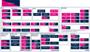
3.1. Boot time assignment[edit source]
3.1.1. On STM32MP1 series[edit source]
The LTDC is used at boot time for displaying a splash screen thanks to the U-Boot framework [1].
Click on ![]() to expand or collapse the legend...
to expand or collapse the legend...
Check boxes illustrate the possible peripheral allocations supported by STM32 MPU Embedded Software:
- ☐ means that the peripheral can be assigned to the given boot time context.
- ☑ means that the peripheral is assigned by default to the given boot time context and that the peripheral is mandatory for the STM32 MPU Embedded Software distribution.
- ⬚ means that the peripheral can be assigned to the given boot time context, but this configuration is not supported in STM32 MPU Embedded Software distribution.
- ✓ is used for system peripherals that cannot be unchecked because they are hardware connected in the device.
The present chapter describes STMicroelectronics recommendations or choice of implementation. Additional possibilities might be described in STM32 MPU reference manuals.
| Domain | Peripheral | Boot time allocation | Comment | |||
|---|---|---|---|---|---|---|
| Instance | Cortex-A7 secure (ROM code) |
Cortex-A7 secure (TF-A BL2) |
Cortex-A7 non-secure (U-Boot) | |||
| Visual | LTDC | LTDC | ☐ | |||
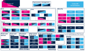
3.1.2. On STM32MP2 series[edit source]
Click on ![]() to expand or collapse the legend...
to expand or collapse the legend...
- ☐ means that the peripheral can be assigned to the given boot time context.
- ☑ means that the peripheral is assigned by default to the given boot time context and that the peripheral is mandatory for the STM32 MPU Embedded Software distribution.
- ⬚ means that the peripheral can be assigned to the given boot time context, but this configuration is not supported in STM32 MPU Embedded Software distribution.
- ✓ is used for system peripherals that cannot be unchecked because they are hardware connected in the device.
The present chapter describes STMicroelectronics recommendations or choice of implementation. Additional possibilities might be described in STM32MP25 reference manuals.
| Domain | Peripheral | Boot time allocation | Comment | |||
|---|---|---|---|---|---|---|
| Instance | Cortex-A35 secure (ROM code) |
Cortex-A35 secure (TF-A BL2) |
Cortex-A35 non-secure (U-Boot) | |||
| Visual | LTDC |
LTDC | ☐ | ☐ | ☐ | Shareable at internal peripheral level thanks to the RIF: see the boot time allocation per feature |
The below table shows the possible boot time allocations for the features of the LTDC instance.
| Feature | Boot time allocation |
Comment | ||
|---|---|---|---|---|
| Cortex-A35 secure (ROM code) |
Cortex-A35 secure (TF-A BL2) |
Cortex-A35 non-secure (U-Boot) | ||
| CMN | ☑ | |||
| L0L1 | ☑ | |||
| L2 | ☐ | |||
| ROT | ☑ | |||
3.2. Runtime assignment[edit source]
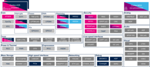
3.2.1. On STM32MP13x lines [edit source]
Click on ![]() to expand or collapse the legend...
to expand or collapse the legend...
Check boxes illustrate the possible peripheral allocations supported by STM32 MPU Embedded Software:
- ☐ means that the peripheral can be assigned to the given runtime context.
- ☑ means that the peripheral is assigned by default to the given runtime context and that the peripheral is mandatory for the STM32 MPU Embedded Software distribution.
- ⬚ means that the peripheral can be assigned to the given runtime context, but this configuration is not supported in STM32 MPU Embedded Software distribution.
- ✓ is used for system peripherals that cannot be unchecked because they are hardware connected in the device.
Refer to How to assign an internal peripheral to an execution context for more information on how to assign peripherals manually or via STM32CubeMX.
The present chapter describes STMicroelectronics recommendations or choice of implementation. Additional possibilities might be described in STM32MP13 reference manuals.
| Domain | Peripheral | Runtime allocation | Comment | ||
|---|---|---|---|---|---|
| Instance | Cortex-A7 secure (OP-TEE) |
Cortex-A7 non-secure (Linux) | |||
| Visual | LTDC | LTDC | ☐ | ☐ | Shareable (multiple choices supported) |
3.2.2. On STM32MP15x lines [edit source]
Click on ![]() to expand or collapse the legend...
to expand or collapse the legend...
Check boxes illustrate the possible peripheral allocations supported by STM32 MPU Embedded Software:
- ☐ means that the peripheral can be assigned to the given runtime context.
- ☑ means that the peripheral is assigned by default to the given runtime context and that the peripheral is mandatory for the STM32 MPU Embedded Software distribution.
- ⬚ means that the peripheral can be assigned to the given runtime context, but this configuration is not supported in STM32 MPU Embedded Software distribution.
- ✓ is used for system peripherals that cannot be unchecked because they are hardware connected in the device.
Refer to How to assign an internal peripheral to an execution context for more information on how to assign peripherals manually or via STM32CubeMX.
The present chapter describes STMicroelectronics recommendations or choice of implementation. Additional possiblities might be described in STM32MP15 reference manuals.
| Domain | Peripheral | Runtime allocation | Comment | |||
|---|---|---|---|---|---|---|
| Instance | Cortex-A7 secure (OP-TEE) |
Cortex-A7 non-secure (Linux) |
Cortex-M4 (STM32Cube) | |||
| Visual | LTDC | LTDC | ☐ | |||
3.2.3. On STM32MP25x lines [edit source]
Click on ![]() to expand or collapse the legend...
to expand or collapse the legend...
Check boxes illustrate the possible peripheral allocations supported by STM32 MPU Embedded Software:
- ☐ means that the peripheral can be assigned to the given runtime context.
- ☑ means that the peripheral is assigned by default to the given runtime context and that the peripheral is mandatory for the STM32 MPU Embedded Software distribution.
- ⬚ means that the peripheral can be assigned to the given runtime context, but this configuration is not supported in STM32 MPU Embedded Software distribution.
- ✓ is used for system peripherals that cannot be unchecked because they are hardware connected in the device.
The present chapter describes STMicroelectronics recommendations or choice of implementation. Additional possibilities might be described in STM32MP25 reference manuals.
| Domain | Peripheral | Runtime allocation | Comment | |||||
|---|---|---|---|---|---|---|---|---|
| Instance | Cortex-A35 secure (OP-TEE / TF-A BL31) |
Cortex-A35 non-secure (Linux) |
Cortex-M33 secure (TF-M) |
Cortex-M33 non-secure (STM32Cube) |
Cortex-M0+ (STM32Cube) | |||
| Visual | LTDC |
LTDC | ☐OP-TEE | ☐ | ☐ | ☐ | ☐ | Shareable at internal peripheral level thanks to the RIF: see the runtime allocation per feature |
The below table shows the possible runtime allocations for the features of the LTDC instance.
| Feature | Runtime allocation |
Comment | ||||
|---|---|---|---|---|---|---|
| Cortex-A35 secure (OP-TEE / TF-A BL31) |
Cortex-A35 non-secure (Linux) |
Cortex-M33 secure (TF-M) |
Cortex-M33 non-secure (STM32Cube) |
Cortex-M0+ (STM32Cube) | ||
| CMN | ⬚OP-TEE | ☑ | ⬚ | ☐ | ||
| L0L1 | ⬚OP-TEE | ☑ | ⬚ | ☐ | ||
| L2 | ☑OP-TEE | ☐ | ⬚ | ☐ | ||
| ROT | ⬚OP-TEE | ☑ | ⬚ | ☐ | ||
4. Software frameworks and drivers[edit source]
Below are listed the software frameworks and drivers managing the LTDC peripheral for the embedded software components listed in the above tables.
- Linux®: DRM/KMS framework
- OP-TEE: OP-TEE framework (for the trusted UI)
- On STM32MP13x lines , the LTDC can be set secure thanks to the ETZPC internal peripheral : this is done at runtime when OP-TEE trusted user interface (Trusted UI) is launched in order to switch the LTDC control and the LTDC input layer2 as secure, to display a secure content that cannot be modified from the non-secure world.
- On STM32MP25x lines , the LTDC can be set secure thanks to the RIFSC internal peripheral : this is done at runtime when OP-TEE trusted user interface (Trusted UI) is launched in order to switch the LTDC control and the LTDC input layer3 as secure, to display a secure content that cannot be modified from the non-secure world.
- On STM32MP13x lines
- U-Boot: U-Boot framework (for the display splash screen)
- STM32Cube:
- On STM32MP13x lines : LTDC HAL driver and header file of LTDC HAL module
- On STM32MP25x lines : LTDC HAL driver and header file of LTDC HAL module
- On STM32MP13x lines
5. How to assign and configure the peripheral[edit source]
The peripheral assignment can be done via the STM32CubeMX graphical tool (and manually completed if needed).
This tool also helps to configure the peripheral:
- partial device trees (pin control and clock tree) generation for the OpenSTLinux software components,
- HAL initialization code generation for the STM32CubeMPU Package.
The configuration is applied by the firmware running in the context in which the peripheral is assigned.
See also additional information in the LTDC device tree configuration article for Linux®.
6. How to go further[edit source]
Refer to STM32 LTDC application note (AN4861) [2] for a detailed description of the LTDC peripheral and applicable use-cases.
Even if this application note is related to STM32 microcontrollers, it also applies to STM32 MPUs.
You may be interested in the following related articles:
- How to use LTDC layers from CM33 and CA35 simultaneously
- no pages or subcategories
[edit source]
The STM32 LTDC internal peripheral can be used in various "shared" LTDC layers use cases. Please refer to following articles to go further:
7. References[edit source]
Arm® is a registered trademark of Arm Limited (or its subsidiaries) in the US and/or elsewhere. ![]()