1. Article purpose[edit source]
The purpose of this article is to provide guidance on managing the ISP block within the DCMIPP , utilizing the Video4Linux2 (V4L2) framework on the Linux® OS.
2. Overview of DCMIPP ISP Block Diagram[edit source]
2.1. Block diagram[edit source]
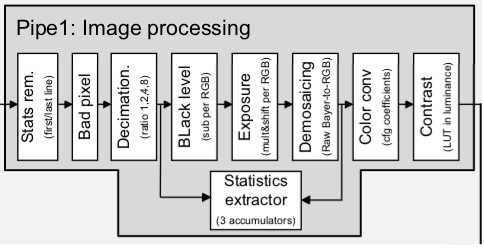
The DCMIPP ISP, which is shared by both pipe1 and pipe2 and is instantiated only once, includes capabilities such as:
- Statistic removal: Eliminates unnecessary metadata, like statistics, from the images received.
- Bad-pixel removal: Automatically identifies and fixes bad pixels in the sensor array.
- Decimation: Reduces the number of pixels to a maximum of 2688 by selecting one pixel out of every 1, 2, 4, or 8.
- Black level correction: Adjusts the black level for each pixel in the red, green, and blue channels.
- Exposure control: Increases the exposure from 0.0 up to 255.99 times.
- Demosaicing: Transforms RawBayer format to RGB and supports NIR patterns of sizes 2x2 and 4x4.
- Statistics extract: Computes average values for red, green, blue, and luminance, including dynamic bins.
- Color conversion: Offers color conversion with flexible, fully programmable coefficients.
- Contrast:Enhances contrast through luminance adjustment.
Refer to the STM32 MPU reference manuals for the complete list of features.
2.2. The software topology[edit source]
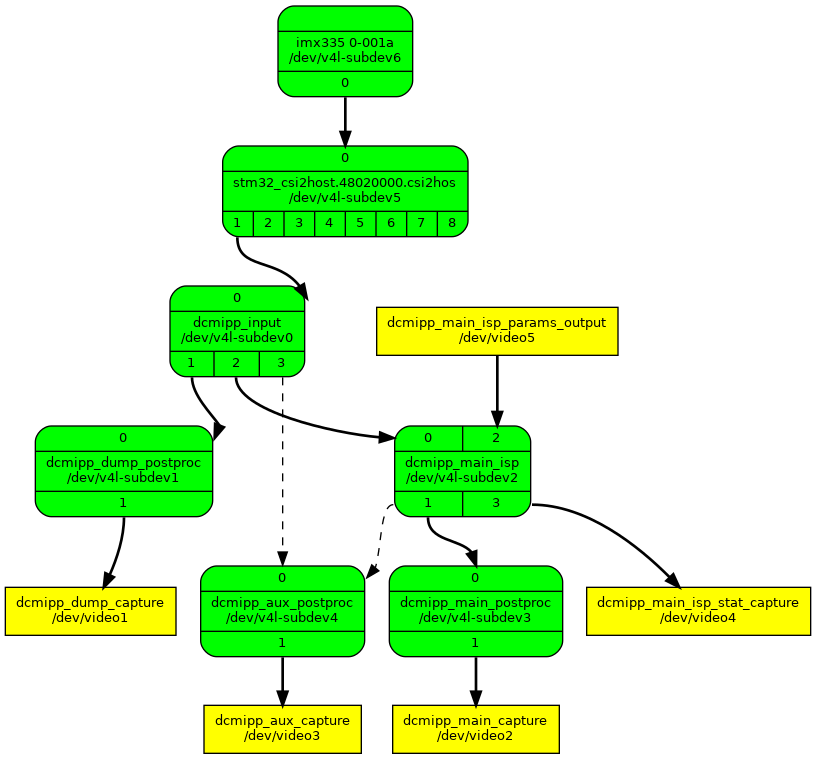
The diagram presented above illustrates the complete media-controller topology of the DCMIPP, including the ISP subdevice called dcmipp_main_isp.
Full control of the ISP is done by using both the v4l2-subdev pad API and dedicated video devices linked to the dcmipp_main_isp subdev.
All settings affecting the frame size or format are done via the dcmipp_main_isp pad (such as format, compose and crop settings), while others features are managed through two video device. The dcmipp_main_isp_params_output video output device allows to inject ISP block configuration while dcmipp_main_isp_stat_capture video capture device allows for control and capture of statistics data generated by the ISP.
3. DCMIPP ISP control[edit source]
3.1. dcmipp_main_isp pad interface controls[edit source]
The table below outlines the association of features that can be accessed using the v4l2 sub-device pad API.
| Feature / Block | Integration with dcmipp_main_isp |
|---|---|
| Statistic removal | crop selection on pad[0] (SINK), with only the top and height fields valid |
| Decimation | compose selection on pad[0] (SINK) |
| Demosaicing | Automatically activated when ISP block input format on pad[0] (SINK) is a RAW format |
3.2. DCMIPP ISP block parameter video output device dcmipp_main_isp_params_output[edit source]
3.3. DCMIPP ISP statistics control & capture video device dcmipp_main_isp_stat_capture[edit source]
3.4. The available controls[edit source]
Further controls are available and applicable on the dcmipp_main_isp subdev:
- demosaicing_peak / demosaicing_horizontal_line / demosaicing_vertical_line / demosaicing_edge: control of the strength of the demosaicing algorithms. Please refer to the refman in order to get more detail about the implemented demosaicing algorithms.
- blacklevel_rgb: unique value to be applied for all R/G/B components for blacklevel compensation
- bad_pixel_control: control of the strength of the bad pixels detection algorithm
- bad_pixel_count: returns the amount of bad pixels detected within the last frame handled by the ISP block
Exposure / contrast and color conversion blocks requires more informations so controls below must provided using specific structures
- isp_exposure_block_control: this control is used to apply settings into the exposure block via the struct v4l2_ctrl_isp_exposure below matching the parameters required by the HW block and described within the RefMan.
/**
 * struct v4l2_ctrl_isp_exposure - Exposure Block control within an ISP
 *
 * @enable: boolean indicating if the exposure compensation should be enabled or not
 * @shift_R: shift for RED component
 * @mult_R: multiply for RED component
 * @shift_G: shift for GREEN component
 * @mult_G: multiply for GREEN component
 * @shift_B: shift for BLUE component
 * @mult_B: multiply for BLUE component
 */
struct v4l2_ctrl_isp_exposure {
        bool enable;
        __u8 shift_R;
        __u8 mult_R;
        __u8 shift_G;
        __u8 mult_G;
        __u8 shift_B;
        __u8 mult_B;
};
- isp_contrast_block_control: this control is used to apply settings into the contrast block via the struct v4l2_ctrl_isp_contrast below matching the parameters required by the HW block and described within the RefMan.
/**
 * struct v4l2_ctrl_isp_contrast - Contrast Block control within an ISP
 *
 * @enable: boolean indicating if the contrast compensation should be enabled or not
 * @lum: luminance increase value table (9 * 8 bits)
 */
struct v4l2_ctrl_isp_contrast {
        bool enable;
        __u8 lum[9];
};
- isp_color_conversion_block_cont: this control is used to apply settings into the color conversion block via the struct v4l2_ctrl_isp_color_conv below matching the parameters required by the HW block and described within the RefMan. If used, it will override the color conversion settings done automatically by the subdev based on sink & source formats.
/**
 * struct v4l2_ctrl_isp_color_conv - Color Conversion parameters within an ISP
 *
 * @enable: boolean indicating if the color conversion should be enabled or not
 * @clamping: boolean indicating if the converted color shall be clamped or not
 * @clamping_as_rgb: boolean indicating if the clamping applies to RGB color space (YUV otherwise)
 * @coeff: color conversion coefficients of the matrix (RGB 3x3 + 1 offset column)
 */
struct v4l2_ctrl_isp_color_conv {
        bool enable;
        bool clamping;
        bool clamping_as_rgb;
        __u16 coeff[3][4];
};
3.5. The statistic extraction[edit source]
3.5.1. Statistics buffer format[edit source]
Statistics generated by the DCMIPP are available via the dcmipp_main_isp_stat_capture V4L2 device. The DCMIPP generated two types of statistics AVERAGE and BINS which are made available via the struct stm32_dcmipp_stat_buf described below.
struct stm32_dcmipp_stat_buf {
        __u32 average_RGB[3];
        __u32 bins[12];
} __packed;
- average_RGB: contains the average value of each component in the statistic area of the frame
- bins: 12 dynamic bins of based on luminance in order to perform later on contrast enhancement
Each buffer extract of the V4L2 device (of type V4L2_BUF_TYPE_META_CAPTURE) will contain one struct stm32_dcmipp_stat_buf, using a dedicated dataformat V4L2_META_FMT_ST_ISP_STAT.
3.5.2. Statistics controls[edit source]
The dcmipp_main_isp_stat_capture V4L2 device also exposes controls in order to tune the statistics extraction:
- ISP stat region control (V4L2_CID_ISP_STAT_REGION): control the statistics extraction area. Allows to define the area of the frame from which statistics are processed. The following struct v4l2_ctrl_isp_stat_region is used to set the control. For the time being there must be only a unique region hence nb_regions should be set to 1.
/**
 * struct v4l2_ctrl_isp_stat_region - Region where ISP statistics are collected
 *
 * @nb_regions: number of regions
 * @top: top coordinate of a region
 * @left: left coordinate of a region
 * @width: width of a region
 * @height: height of a region
 */
struct v4l2_ctrl_isp_stat_region {
        __u8 nb_regions;
        __u32 top[25];
        __u32 left[25];
        __u32 width[25];
        __u32 height[25];
};
- ISP stat location control (V4L2_CID_ISP_STAT_LOCATION): control the statistic extraction position within the DCMIPP pipeline.
- 0: statistics are extracted prior to frame processing (aka beginning of the pipeline)
- 1: statistics are extracted after demosaicing block
- ISP stat average filter control (V4L2_CID_ISP_STAT_AVG_FILTER): control the filtering of pixels in the statistics AVERAGE processing
- 0: no filtering performed, all pixels used for average calculation
- 1: pixels with value < 16 or >= 240 are discarded from average calculation
- 2: pixels with value < 32 or >= 224 are discarded from average calculation
- 3: pixels with value < 64 or >= 192 are discarded from average calculation
- ISP stat bin component control (V4L2_CID_ISP_STAT_BIN_COMP): control which component is used for BINS processing (R/G/B or Luminance)
- 0: R component used
- 1: G component used
- 2: B component used
- 3: luminance used
4. Use case examples[edit source]
| Coming soon |
5. Debug[edit source]
| Coming soon |

