1. Article purpose[edit source]
The purpose of this article is to:
- briefly introduce the SYSRAM internal memory peripheral and its main features,
- indicate the peripheral instances assignment at boot time and their assignment at runtime (including whether instances can be allocated to secure contexts),
- list the software frameworks and drivers managing the peripheral,
- explain how to configure the peripheral.
2. Peripheral overview[edit source]
The SYSRAM peripheral is an internal memory peripheral. It is physically located near the Arm® Cortex-A to optimize the core performance.
- STM32MP13x lines
 SYSRAM is 128-Kbyte wide
 - STM32MP15x lines SYSRAM is 256-Kbyte wide
- STM32MP2 series SYSRAM is 256-Kbyte wide
On STM32MP1 series, the SYSRAM is protected by ETZPC firewall. By default, SYSRAM access is granted to Cortex-A7 secure. The SYSRAM can be split into 2 memory regions with a 4-Kbyte granularity:
- a low secure region
- a high non-secure region
On STM32MP2 series, the SYSRAM is protected by RISAB memory firewall, allowing to create some 4-Kbyte granularity memory regions with different access rights to share SYSRAM between the different execution contexts of the platform. By default, SYSRAM access is granted to Cortex-A35 secure.
Refer to the STM32 MPU reference manuals for the complete list of features, and to the software frameworks and drivers, introduced below, to see which features are implemented.
3. Peripheral usage[edit source]
This chapter is applicable in the scope of the OpenSTLinux BSP running on the Arm® Cortex®-A processor(s), and the STM32CubeMPU Package running on the Arm® Cortex®-M processor.
3.1. Boot time assignment[edit source]
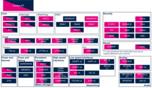
3.1.1. On STM32MP13x lines [edit source]
The ROM code leaves the SYSRAM secure when it jumps to the entry point of the FSBL that it has just loaded into the SYSRAM.
The FSBL does not have to keep any context in SYSRAM when it jumps to the SSBL: each boot stage is independent from the other.
Click on ![]() to expand or collapse the legend...
to expand or collapse the legend...
Check boxes illustrate the possible peripheral allocations supported by STM32 MPU Embedded Software:
- ☐ means that the peripheral can be assigned to the given boot time context.
- ☑ means that the peripheral is assigned by default to the given boot time context and that the peripheral is mandatory for the STM32 MPU Embedded Software distribution.
- ⬚ means that the peripheral can be assigned to the given boot time context, but this configuration is not supported in STM32 MPU Embedded Software distribution.
- ✓ is used for system peripherals that cannot be unchecked because they are hardware connected in the device.
The present chapter describes STMicroelectronics recommendations or choice of implementation. Additional possibilities might be described in STM32 MPU reference manuals.
| Domain | Peripheral | Boot time allocation | Comment | |||
|---|---|---|---|---|---|---|
| Instance | Cortex-A7 secure (ROM code) |
Cortex-A7 secure (TF-A BL2) |
Cortex-A7 non-secure (U-Boot) | |||
| Core/RAM | SYSRAM | SYSRAM | ✓ | ✓ | ||
3.1.2. On STM32MP15x lines [edit source]
The ROM code mainly configures the SYSRAM as a secure peripheral during its execution. It uses 9 Kbytes located at the beginning of the SYSRAM to store its read and write data. Among them, it stores the boot context in the first 512 bytes of SYSRAM: this boot context contains several information (such as the selected boot device) and pointers to the ROM code exported services (used for secure boot authentication). The ROM code loads the FSBL just after the boot context, into the remaining 247 Kbytes of SYSRAM, and eventually branches the Cortex®-A7 core 0 execution to this FSBL.
The FSBL code can use the whole SYSRAM, but it must take care not to overwrite the boot context before taking it into account.
Click on ![]() to expand or collapse the legend...
to expand or collapse the legend...
Check boxes illustrate the possible peripheral allocations supported by STM32 MPU Embedded Software:
- ☐ means that the peripheral can be assigned to the given boot time context.
- ☑ means that the peripheral is assigned by default to the given boot time context and that the peripheral is mandatory for the STM32 MPU Embedded Software distribution.
- ⬚ means that the peripheral can be assigned to the given boot time context, but this configuration is not supported in STM32 MPU Embedded Software distribution.
- ✓ is used for system peripherals that cannot be unchecked because they are hardware connected in the device.
The present chapter describes STMicroelectronics recommendations or choice of implementation. Additional possibilities might be described in STM32 MPU reference manuals.
| Domain | Peripheral | Boot time allocation | Comment | |||
|---|---|---|---|---|---|---|
| Instance | Cortex-A7 secure (ROM code) |
Cortex-A7 secure (TF-A BL2) |
Cortex-A7 non-secure (U-Boot) | |||
| Core/RAM | SYSRAM | SYSRAM | ✓ | ✓ | ||
3.1.3. On STM32MP2 series[edit source]
The ROM code leaves the SYSRAM secure when it jumps to the entry point of the FSBL that it has just loaded into the SYSRAM.
The FSBL does not have to keep any context in SYSRAM when it jumps to the next boot stages: each boot stage is independent from the other.
Click on ![]() to expand or collapse the legend...
to expand or collapse the legend...
- ☐ means that the peripheral can be assigned to the given boot time context.
- ☑ means that the peripheral is assigned by default to the given boot time context and that the peripheral is mandatory for the STM32 MPU Embedded Software distribution.
- ⬚ means that the peripheral can be assigned to the given boot time context, but this configuration is not supported in STM32 MPU Embedded Software distribution.
- ✓ is used for system peripherals that cannot be unchecked because they are hardware connected in the device.
The present chapter describes STMicroelectronics recommendations or choice of implementation. Additional possibilities might be described in STM32MP25 reference manuals.
| Domain | Peripheral | Boot time allocation | Comment | |||
|---|---|---|---|---|---|---|
| Instance | Cortex-A35 secure (ROM code) |
Cortex-A35 secure (TF-A BL2) |
Cortex-A35 non-secure (U-Boot) | |||
| Core/RAM | SYSRAM | SYSRAM | ✓ | ✓ | ||
3.2. Runtime assignment[edit source]
3.2.1. On STM32MP13x lines [edit source]
In OSTL distribution, the SYSRAM runtime mapping is the one reached at the end of the boot. It is consequently fully secure and can contain a secure monitor functions provided by OP-TEE secure OS to handle low power modes.
STM32MP13 embeds an on-the-fly DDR cyphering engine, the DDRMCE internal peripheral, allowing to put OP-TEE secure OS sensitive code inside the external DDR, instead of the SYSRAM.
You may decide to split the SYSRAM at runtime. In this case:
- set the SYSRAM bottom secure, for a Cortex®-A7 secure monitor or a secure OS (such as OP-TEE)
and
- set the SYSRAM top non-secure, for instance for using in Linux® as reserved memory
Click on ![]() to expand or collapse the legend...
to expand or collapse the legend...
Check boxes illustrate the possible peripheral allocations supported by STM32 MPU Embedded Software:
- ☐ means that the peripheral can be assigned to the given runtime context.
- ☑ means that the peripheral is assigned by default to the given runtime context and that the peripheral is mandatory for the STM32 MPU Embedded Software distribution.
- ⬚ means that the peripheral can be assigned to the given runtime context, but this configuration is not supported in STM32 MPU Embedded Software distribution.
- ✓ is used for system peripherals that cannot be unchecked because they are hardware connected in the device.
Refer to How to assign an internal peripheral to an execution context for more information on how to assign peripherals manually or via STM32CubeMX.
The present chapter describes STMicroelectronics recommendations or choice of implementation. Additional possibilities might be described in STM32MP13 reference manuals.
| Domain | Peripheral | Runtime allocation | Comment | ||
|---|---|---|---|---|---|
| Instance | Cortex-A7 secure (OP-TEE) |
Cortex-A7 non-secure (Linux) | |||
| Core/RAM | SYSRAM | SYSRAM | ☑ | ☐ | Shareable (multiple choices supported)
Secure section required for low power entry and exit |
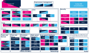
3.2.2. On STM32MP15x lines [edit source]
In OSTL distribution, the SYSRAM runtime mapping is the one reached at the end of the boot. It is consequently fully secure and can contain a secure OS (like OP-TEE).
You may decide to split the SYSRAM at runtime. In this case:
- set the SYSRAM bottom secure, for a Cortex®-A7 secure monitor or a secure OS (such as OP-TEE)
and
- set the SYSRAM top non-secure, for instance for using in Linux® as reserved memory
Click on ![]() to expand or collapse the legend...
to expand or collapse the legend...
Check boxes illustrate the possible peripheral allocations supported by STM32 MPU Embedded Software:
- ☐ means that the peripheral can be assigned to the given runtime context.
- ☑ means that the peripheral is assigned by default to the given runtime context and that the peripheral is mandatory for the STM32 MPU Embedded Software distribution.
- ⬚ means that the peripheral can be assigned to the given runtime context, but this configuration is not supported in STM32 MPU Embedded Software distribution.
- ✓ is used for system peripherals that cannot be unchecked because they are hardware connected in the device.
Refer to How to assign an internal peripheral to an execution context for more information on how to assign peripherals manually or via STM32CubeMX.
The present chapter describes STMicroelectronics recommendations or choice of implementation. Additional possiblities might be described in STM32MP15 reference manuals.
| Domain | Peripheral | Runtime allocation | Comment | |||
|---|---|---|---|---|---|---|
| Instance | Cortex-A7 secure (OP-TEE) |
Cortex-A7 non-secure (Linux) |
Cortex-M4 (STM32Cube) | |||
| Core/RAM | SYSRAM | SYSRAM | ☑ | ☐ | ⬚ | Shareable (multiple choices supported)
Secure section required for low power entry and exit |
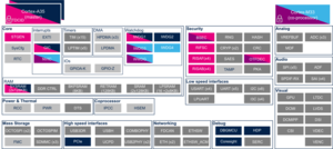
3.2.3. On STM32MP25x lines [edit source]
In OSTL distribution, the SYSRAM runtime mapping is split into two regions.
- one Cortex-A35 secure region dedicated to secure monitor which handles Cortex-A35 cluster
- one Cortex-A35 non-secure region assigned to Linux kernel for HPDMA linked list management
As SYSRAM is used by ROM code during D1Standby exit low power sequence, it is not recommended to assign SYSRAM to Cortex-M33 except if product doesn't plan to support Run2 and (LPLV)Stop2 low power modes.
Click on ![]() to expand or collapse the legend...
to expand or collapse the legend...
Check boxes illustrate the possible peripheral allocations supported by STM32 MPU Embedded Software:
- ☐ means that the peripheral can be assigned to the given runtime context.
- ☑ means that the peripheral is assigned by default to the given runtime context and that the peripheral is mandatory for the STM32 MPU Embedded Software distribution.
- ⬚ means that the peripheral can be assigned to the given runtime context, but this configuration is not supported in STM32 MPU Embedded Software distribution.
- ✓ is used for system peripherals that cannot be unchecked because they are hardware connected in the device.
The present chapter describes STMicroelectronics recommendations or choice of implementation. Additional possibilities might be described in STM32MP25 reference manuals.
| Domain | Peripheral | Runtime allocation | Comment | |||||
|---|---|---|---|---|---|---|---|---|
| Instance | Cortex-A35 secure (OP-TEE / TF-A BL31) |
Cortex-A35 non-secure (Linux) |
Cortex-M33 secure (TF-M) |
Cortex-M33 non-secure (STM32Cube) |
Cortex-M0+ (STM32Cube) | |||
| Core/RAM | SYSRAM | SYSRAM | ☑BL31 ☐OP-TEE |
☑ | ☐ | ☐ |
Cortex-A35 secure section required for low power entry and exit | |
4. Software frameworks and drivers[edit source]
Thus, below are listed the software frameworks and drivers managing the XXX peripheral for the embedded software components listed in the above tables.
- Linux®: Linux reserved memory
- OP-TEE: OP-TEE
- TF-A BL2: TF-A BL2
- TF-A BL31: TF-A BL31
- TF-M: TF-M
5. How to assign and configure the peripheral[edit source]
The peripheral assignment can be done via the STM32CubeMX graphical tool (and manually completed if needed).
This tool also helps to configure the peripheral:
- partial device trees (pin control and clock tree) generation for the OpenSTLinux software components,
- HAL initialization code generation for the STM32CubeMPU Package.
The configuration is applied by the firmware running in the context in which the peripheral is assigned.
Arm® is a registered trademark of Arm Limited (or its subsidiaries) in the US and/or elsewhere. ![]()