1 Step by step approach[edit source]
The STM32CubeMP13 Package is part of the STM32 MPU embedded software offer. It runs on the Arm® Cortex®-A7 core.
This article shows how to start up a STM32MP135x-DK Discovery kit ![]() (flexible and complete development platform for the STM32MP13x lines
(flexible and complete development platform for the STM32MP13x lines ![]() ) with the STM32CubeMP13 package. It is valid for STM32MP135F-DK Discovery kit
) with the STM32CubeMP13 package. It is valid for STM32MP135F-DK Discovery kit ![]() : the part numbers are specified in the STM32MP13 microprocessor part numbers article.
: the part numbers are specified in the STM32MP13 microprocessor part numbers article.
It lists the required material, points to the board features description, and gives the step-by-step process to set up the system.
Finally, it explains how to develop, build and run existing or new examples to discover some of the board capabilities.
The steps to get the STM32MP135x-DK Discovery kit ![]() up and running, are:
up and running, are:
☐ Checking the material
☐ Assembling the board
☐ Installing the tools : Installing the components to develop software running Arm® Cortex®-A7 with STM32CubeMPU Package
- • Installing STM32CubeIDE (mandatory for any development on Arm® Cortex®-A7)
- • Installing the STM32CubeMX (optional only if you plan to use graphical user interface that guides you through the initial configuration of a firmware project.)
- • Installing the STM32CubeMPU Package (mandatory)
Once the board is assembled and required tools and software are installed on host PC, there are different ways (boot modes) to load the firmware into the Arm® Cortex®-A7 core:
- the serial boot mode (Forced USB or UART boot for programming firmware on virgin device through serial interface)
- the engineering boot mode (the firmware is loaded from the IDE).
- the microSD™ card boot mode (the firmware is loaded from programmed microSD™ card)
Different boot modes are to be used depending on the development or production phase. Engineering boot mode is used during development to connect to the debugger and to use IDE.
Other boot modes are used during production phase for programming images into target or boot from external memory.
2 Checking the material[edit source]
Mandatory
| PC | Linux® or Windows® operating systems. See PC prerequisites for more details on the required configurations. |
| STM32MP135x-DK Discovery kit | Flexible and complete development platform for the STM32MP135 microprocessor device including:
|
| Power supply | Including:
|
| microSD™ card |
Populated with STM32CubeMPU firmware, the microSD™ card can be used as external memory to populate firmware into board |
| USB Micro-B cable | To connect the STM32MP135x-DK Discovery kit to the PC through the USB Micro-B (ST-LINK/V2-1) connector. |
| USB Type-C® cable | To connect the STM32MP135x-DK Discovery kit to a USB OTG device through the USB Type-C® connector. |
Optional
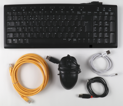
| USB keyboard and mouse | Through its USB Type-A connectors, the STM32MP135x-DK Discovery kit can be equipped with a full-size keyboard and mouse. |
| Ethernet cable | To connect the STM32MP135x-DK Discovery kit to a network through the RJ45 connector. |
Optional: It is possible to plug more devices and extension boards to the STM32MP135x-DK Discovery kit by means of its expansion connectors such as the GPIO expansion connector.
The following figure shows the optional material (not included in STM32MP135x-DK Discovery kit ![]() package).
package).
3 Assembling the board[edit source]
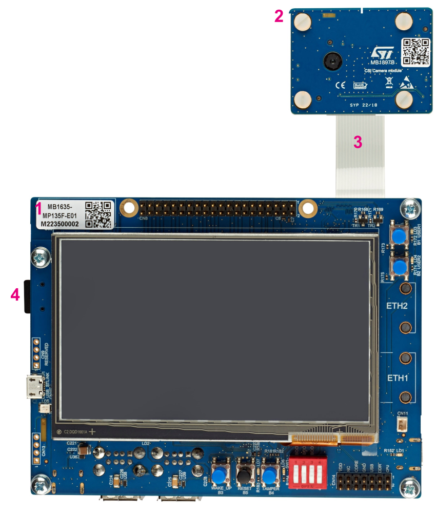
The STM32MP135F-DK Discovery kit ![]() package is composed of the items listed below.
package is composed of the items listed below.
| Position | Description |
|---|---|
| 1 | MB1635 mother board |
| 2 | MB1897 camera module (GalaxyCore GC2145 camera sensor) |
| 3 | Camera module flat cable |
| 4 | microSD™ card |
Note that the STM32MP135F-DK Discovery kit ![]() delivery does not contain a USB cable or a USB charger.
delivery does not contain a USB cable or a USB charger.
4 Installing tools[edit source]
This section is for installing the components required to develop software running on Arm® Cortex®-A7 with STM32CubeMPU Package.
4.1 Installing STM32CubeIDE[edit source]
It is needed if you want to run existing examples or modify or add software running on Arm® Cortex®-A7.
The table below explains how to download and install STM32CubeIDE which addresses STM32 MCU, and also provides support for Cortex-A7 inside STM32 MPU.
STM32 MPU support, inside STM32CubeIDE, is available on Linux® and Windows® host PCs, but it is NOT on macOS®.
| STM32CubeIDE for Linux® host PC | STM32CubeIDE for Windows® host PC | |
|---|---|---|
| Download |
Version 1.15.0
|
Version 1.15.0
|
| Installation guide | ||
| User manual | ||
| Detailed release note |
| |
Minor releases may be available from the update site. Check chapter 10 in (UM2609) for more information on how to update STM32CubeIDE.
4.2 Installing STM32CubeMX[edit source]
Optional step: This is required only if developer wants to use STM32CubeMX for initial configuration of firmware project. Refer to STM32CubeMX release note for more details.
5 Installing the STM32CubeMPU Package[edit source]
Prerequisite: the STM32CubeIDE is installed.
- The STM32CubeMP13 Package is delivered through an archive file named en.stm32cubemp13-v1-1-0.zip.
- Download and install the STM32CubeMP13 Package
The software package is provided AS IS, and by downloading it, you agree to be bound to the terms of the software license agreement (SLA0048). The detailed content licenses can be found here.
| STM32CubeMP13 Package - v1.1.0 release | ||
|---|---|---|
| From st.com | From github | |
| Download |
|
|
| Installation |
|
|
| Release note | Details about the content of the STM32CubeMP13 Package are available in STM32CubeMP13 Package content article and in the Release_Notes.html file. | |
STM32Cube_FW_MP13_V1.1.0		STM32CubeMP13 Package: details in STM32CubeMP13 Package content article
├── Drivers
│   ├── BSP				BSP drivers for the supported STM32MP13 boards
│   │   └── [...]
│   ├── CMSIS
│   │   └── [...]
│   └── STM32MP13xx_HAL_Driver		HAL drivers for the supported STM32MP13 devices
│       └── [...]
├── _htmresc
│   └── [...]
├── License.md
├── Middlewares
│   └── [...]
├── package.xml
├── Projects
│   ├── STM32CubeProjectsList.html	List of examples and applications for STM32CubeMP13 Package
│   ├── STM32MP135C-DK			Set of examples and applications → STM32MP13 Discovery kits
│   │   └── [...]
│   └── STM32MP13XX_CUSTOM_HW		Set of examples and applications → STM32MP13 Custom boards
│       └── [...]
├── Readme.md
├── Release_Notes.html			Release note for STM32CubeMP13 Package
└── Utilities
    └── [...]
The STM32CubeMPU Package is now installed: let's develop software running on Arm® Cortex®-A7.
6 Playing with STM32CubeMPU Package[edit source]
All examples and applications, explained below, have been designed to run on a STM32MP135F-DK Discovery kit ![]() integrating an STM32MP135C line
integrating an STM32MP135C line ![]() .
.
Pre-requisites
- STM32CubeMP13 Package and the STM32CubeIDE are installed on your host PC
- ST-Link cable is connected between your host PC and your board.
It is recommended to use the engineering boot mode when developing or debugging an application running on the Arm® Cortex®-A7 core. Selection of engineering boot mode is described in Select boot mode chapter.
This chapter and its sub-chapters aim to explain all steps needed to run an existing example/application using STM32CubeIDE. Once done, you can jump to the chapter How to go further to enhance your experience with the STM32CubeMP13 Package.
6.1 How to run existing examples on Arm Cortex-A7[edit source]
This section explains how to build and execute examples using STM32CubeIDE.
6.1.1 As bare metal[edit source]
Bare metal means that the hardware resources are managed by user application itself without an intervening operating system, such as Azure RTOS.
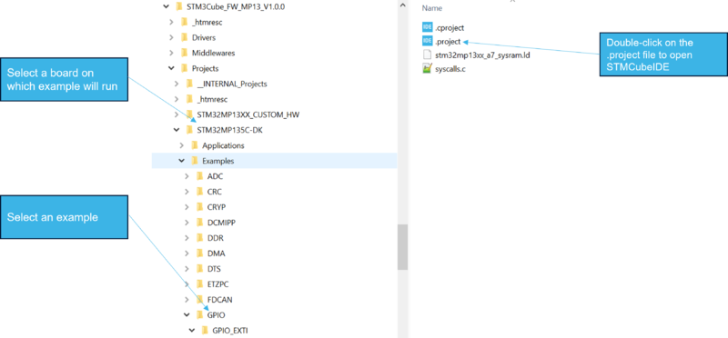
6.1.1.1 Select the example to run[edit source]
First select the example to be run from the package below.
├── Projects
│   ├── STM32MP135C-DK			->Set of examples → STM32MP13 Discovery kits
│   ├── [Applications]
│   ├── [Examples]
│   ├── [External_Loader]
│   ├── [Templates]
6.1.1.2 Build the example[edit source]
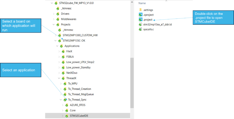
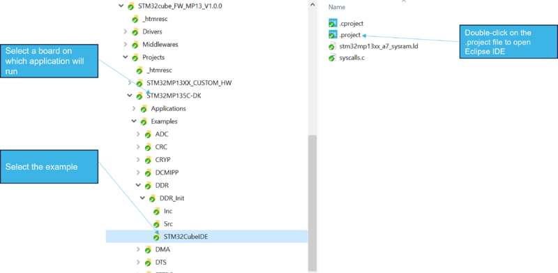
- Open the folder containing the example and double-click on file .project to open STM32CubeIDE:
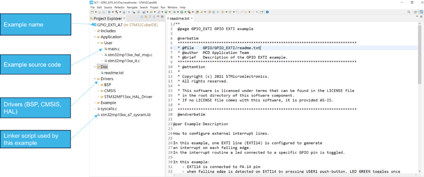
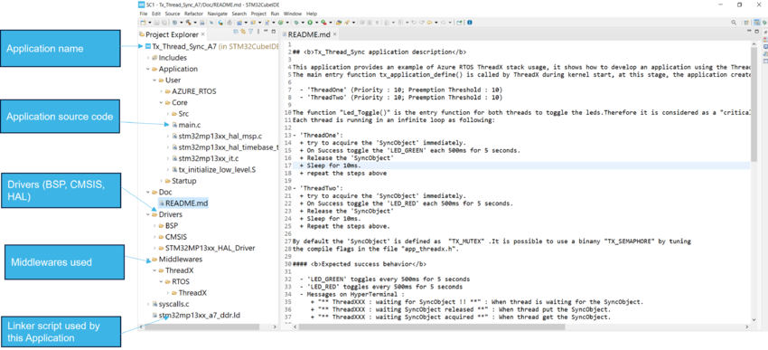
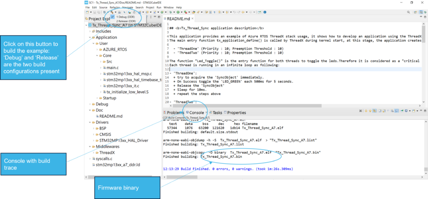
- The directory layout of project containing the example appears like this, in STM32CubeIDE:
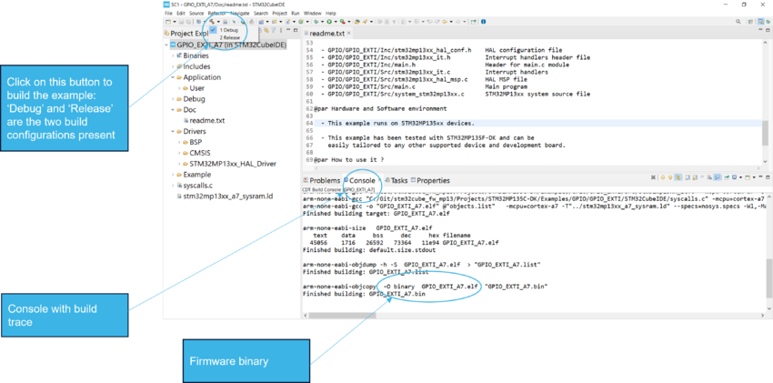
- Click on "Hammer" button to build the example:
6.1.1.3 Select boot mode[edit source]
For flashing images onto your board with STM32CubeIDE, Engineering boot mode is required. For that, boot switches must be set in a specific configuration, defined in here.
6.1.1.4 Read the README file carefully[edit source]
A readme file exists for any example and is available in the folder associated to the example. It provides all the information about the example setup and verdict.
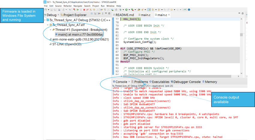
6.1.1.5 Download and run an example from SYSRAM[edit source]
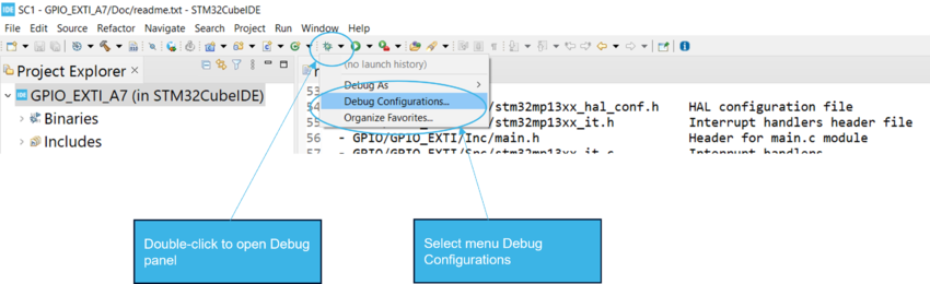
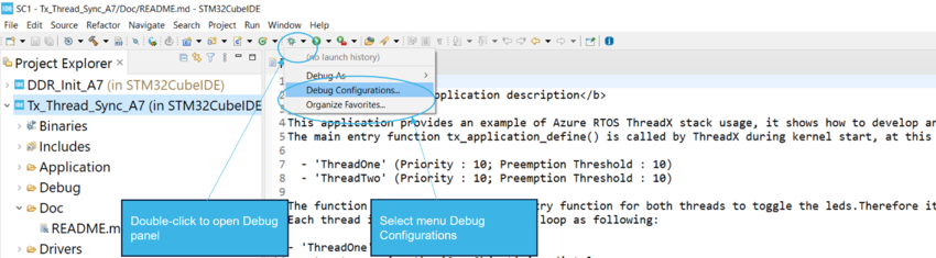
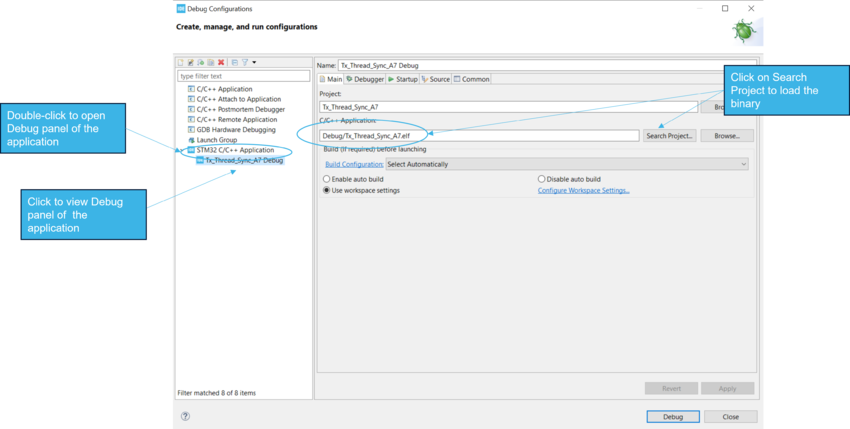
- Open the Debug Configurations panel:
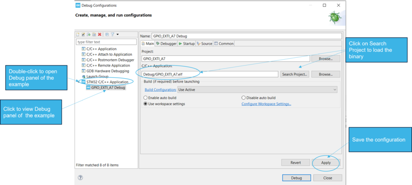
- Configure the Main panel to add the firmware binary:
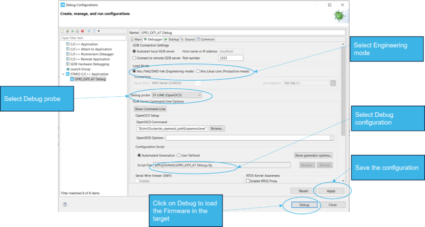
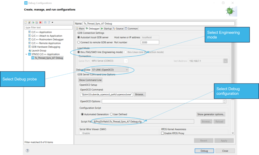
- Configure the Debugger & Startup panel to load and run the firmware in the target:
- Expected verdict of an example is given in associated Readme file.
6.1.2 Integrating AzureRTOS middleware[edit source]
6.1.2.1 Select the application to run[edit source]
First select the application to be run from the package below.
├── Projects
│   ├── STM32MP135C-DK			->Set of applications → STM32MP13 Discovery kits
│   ├── [Applications]
│   ├── [Examples]
│   ├── [External_Loader]
│   ├── [Templates]
6.1.2.2 Build the application[edit source]
- Open the folder containing the application and double-click on file .project:
- The directory layout of project containing the example appears like this, in STM32CubeIDE:
- Click on "Hammer" button to build the application:
6.1.2.3 Select boot mode[edit source]
For flashing images onto your board with STM32CubeIDE, Engineering boot mode is required. For that, boot switches must be set in a specific configuration, defined in here.
6.1.2.4 Read the README file carefully[edit source]
A readme file exists for any application and is available in the folder associated to the application. It provides all the information about the application setup and verdict.
6.1.2.5 Initialize the DDR[edit source]
DDR Initialization is a pre-requisite to download and run application from DDR memory. Effectively, DDR needs to be initialized first with DDR_Init project.
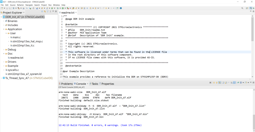
- Open the folder containing the DDR_Init example and double-click on file .project to open STM32CubeIDE:
- Follow same steps as mentioned in Build an application section to build, download and run the DDR_Init example.
- After executing the example, DDR is successfully initialized. This can be validated by referring to 'Readme' of DDR_Init example.
6.1.2.6 Download and run an application from DDR[edit source]
Pre-requisite: DDR must be initialised (refer to Initialize the DDR chapter if not already done).Project should be compiled and linked for DDR (refer to Build application for DDR) After successful completion of DDR initialization, follow the steps mentioned below:
- Open the Debug Configurations panel:
- Configure the Main panel to add the firmware binary:
- Configure the Debugger panel:
- Configure the Startup panel and remove "monitor reset" or "mon reset" command. This is done to avoid reset of DDR clock, initialized by DDR_Init example.
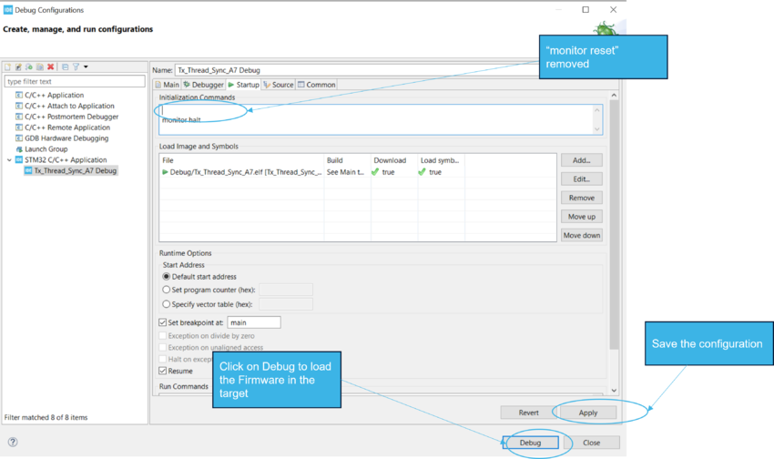
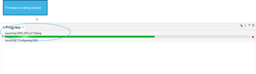
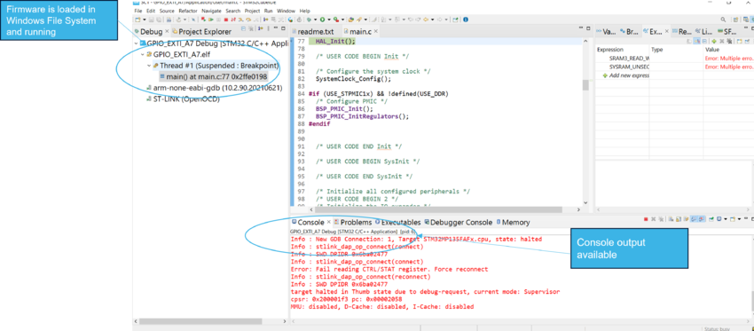
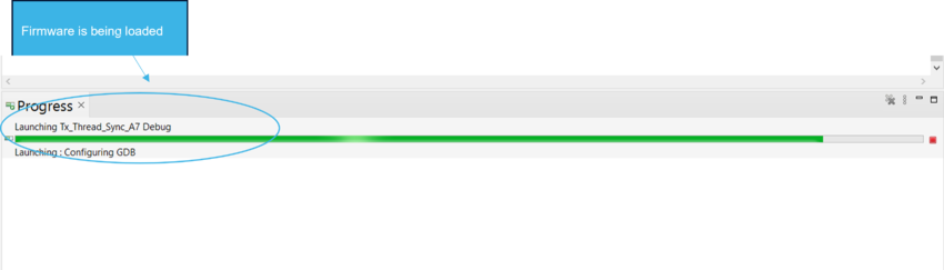
- Download and run the firmware in the target:
- Readme should be checked for expected verdict of the application.
6.2 How to go further[edit source]
6.2.1 How to develop and run your examples or applications[edit source]
6.2.1.1 Create your project for your board[edit source]
A project is board and application specific. To create a new project, you start
- either from the Template project,
- or any available project from Examples or Applications
The Template project has the following characteristics:
- It contains the source code of HAL, CMSIS and BSP drivers which are the minimum components required to develop a code for a given board.
- CMSIS contains separate system and start-up files for AzureRTOS and bare metal use cases.
- e.g. system_stm32mp13xx_A7_azurertos.c and system_stm32mp13xx_A7.c
- e.g. startup_stm32mp135cxx_ca7.c and startup_stm32mp135c_ca7_azurertos.c
- CMSIS contains separate system and start-up files for AzureRTOS and bare metal use cases.
- It contains the include paths for all the firmware components.
- It defines the STM32MP13 supported device, which defines the CMSIS and HAL driver configuration settings.
- It provides pre-configured user files which are ready-to-use as shown below:
- HAL is initialized with default time base with ARM Core SysTick.
- SysTick ISR is implemented for delay management purpose (HAL_Delay()).
- It contains linker script stm32mp13xx_a7_sysram.ld by default to execute from SYSRAM. If code needs to be executed from DDR, do the following changes in linker file:
/*REGION_ALIAS("RAM", DDR_BASE);*/
REGION_ALIAS("RAM", SYSRAM_BASE);   Code is placed and executed from SYSRAM)

REGION_ALIAS("RAM", DDR_BASE);    Code is placed and executed from DDR)
/*REGION_ALIAS("RAM", SYSRAM_BASE); */
6.2.1.2 Build application for DDR (optional)[edit source]
In case, application size exceeds SYSRAM size, it must be executed from DDR. Developer needs to follow below steps in order:
- Add USE_DDR in .cproject file
- Find the reference DDR linker script in Drivers\CMSIS\Device\ST\STM32MP13xx\Source\Templates\gcc\linker\stm32mp13xx_a7_ddr.ld inside STM32CubeMPU package.
- Build the application or example using STM32CubeIDE.
- To execute the example or application, first step is to initialize the DDR and then only example/application can be run from DDR. For delails on this step, jump back to DDR Initialization and Download and run an application from DDR chapters.
6.2.1.3 Create signed application (optional)[edit source]
This section is to explain how a signed binary can be created for your application.
If application needs to be booted by ROM code, then application binary needs to be signed or prepended with the STM32 header.The STM32 header includes mandatory and optional information.
e.g. FSBLA_Sdmmc1_A7_Signed.bin or MP13_BSP_TemplatesA7_DISCO_Signed.bin, delivered as a part of external loader package available in directory Firmware/Projects/STM32MP135C-DK/External_Loader/SD_Ext_Loader. This signed binary can be created by adding post build option in STM32CubeIDE build steps as shown below.
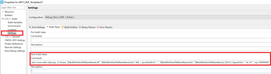
Post build script (postbuild_STM32MP13.sh) is delivered as part of MP13 package and available in directory Utilities/ImageHeader.
6.2.1.4 Add middleware to your project (optional)[edit source]
Your project may need to support additional middleware. This support is available from these middleware stacks: AzureRTOS.
If you have the experience, it is also possible to look in the application source code to find out which source files and which include paths must be added.
- Applications for board STM32MP135F-DK : Applications
6.2.1.5 Configure the firmware components[edit source]
The HAL and middleware components offer a set of build time configuration options using macros #define, declared in a header file.
A template configuration file is provided for each component. It has to be copied to the project folder (usually the configuration file is named xxx_conf_template.h, and the word ‘_template’ needs to be removed when copying it to the project folder).
The configuration file provides enough information to understand the impact of each configuration option. More detailed information is available in the documentation provided with each component.
6.2.1.6 Start the HAL Library[edit source]
After jumping to the main program, the application code must call the function HAL_Init() to initialize the HAL Library. It includes the following tasks:
a) Configuration of the SysTick to generate an interrupt every 1 millisecond with the SysTick interrupt priority TICK_INT_PRIORITY defined in the file stm32mp13xx_hal_conf.h.
b) Configure GIC interrupts.
c) Call to the HAL_MspInit() function defined in the stm32mp13xx_hal_msp.c user file performs global low-level hardware initializations like HSEM clock enable.
6.2.1.7 Configure the system clock[edit source]
The system clock configuration is done by calling the two APIs described below:
a) HAL_RCC_OscConfig(): this API configures the internal and/or external oscillators, as well as the PLL source and factors. The user chooses to configure either one oscillator or all oscillators. The PLL configuration can be skipped if there is no need to run the system at high frequency.
b) HAL_RCC_ClockConfig(): this API configures the system clock source and bus prescalers
6.2.1.8 Initialize the peripheral[edit source]
a) Edit the file stm32mp13xx_hal_msp.c to write to the peripheral HAL_MspInit() function. Proceed as follows:
- Enable the peripheral clock.
- Configure the peripheral GPIOs.
- Configure the DMA channel and enable DMA interrupt (if needed).
- Enable peripheral interrupt (if needed).
b) Edit the stm32mp13xx_it.c file to call on the required interrupt handlers (peripheral and DMA), if needed.
c) Write process complete callback functions if you plan to use peripheral interrupt or DMA.
d) In the main.c file, initialize the peripheral handler structure then call the function HAL_Init() to initialize your peripheral.
6.2.1.9 Develop your application[edit source]
At this stage, your system is ready and you can start developing your application code.
- The HAL provides intuitive and ready-to-use APIs to configure the peripheral. It supports polling, interrupts and a DMA programming model, to accommodate any application requirement.
- For more details on how to use each peripheral and how to manage real-time constraints, refer to the full set of examples and applications provided in the STM32CubeMP13 Package (List of available projects)
6.2.2 How to debug your STM32CubeMP13 package with STM32CubeIDE[edit source]
- Refer to sections Download and run an example from SYSRAM or Download and run an example from DDR.
6.3 How to configure the STM32CubeMP13 package for your board[edit source]
6.3.1 How to initialize your new driver with STM32CubeMX[edit source]
Refer to STM32CubeMX user manual UM1718.
6.4 How to configure the Bootloader for execution from DDR[edit source]
The ROM code starts the processor in secure mode and reads the boot mode configuration. when boot done from microSD™ card, the ROM code loads and runs the FSBLA firmware from the microSD™ card inside the SYSRAM. FSBLA then loads the STM32Cube example into DDR external RAM and jumps to it. Refer to STM32CubeMP13 boot architecture to get more information.
The first stage boot loader, FSBLA_Sdmmc1, is the code used as FSBLA on STM32CubeMP13 as below.
├── Projects
│   ├── STM32MP135C-DK
│   │   ├── Applications
│   │   └── FSBLA
│   │   │   └── FSBLA_Sdmmc1	-> FSBLA code for SDMMC1
To use STM32Cube example loading by FSBLA into DDR, external loader utility should be used. Refer to section How to load and boot from external memory
6.4.1 How to load and boot from external memory[edit source]
During production phase, for flashing images onto your board without using STM32CubeIDE , follow below steps:
- Change the boot mode to serial mode. Refer to Set boot switches to know the appropriate boot switches configuration
- Issue Reset.
- Using External loader utility, load the images into external memory (microSD™ card in this case) using STM32CubeProgrammer through serial interface (UART).
- Once done, change the boot mode to microSD™ card boot. Refer to Set boot switches.
- Issue Reset
- Application in microSD™ card is loaded using FSBLA into DDR and executes from there.
External loader utility is supported for :
- Boot from MicroSD™ card on STM32MP135F-DK board. Refer to Loading application into SD and boot from SD
- Boot from SNOR Flash on custom hardware. Refer to Loading application into SNOR and boot from SNOR
- Boot from eMMC on custom hardware. Refer to Loading application into eMMC and boot from eMMC
Arm® is a registered trademark of Arm Limited (or its subsidiaries) in the US and/or elsewhere. ![]()
Arm® is a registered trademark of Arm Limited (or its subsidiaries) in the US and/or elsewhere. ![]()