This message will disappear after all relevant tasks have been resolved.
Semantic MediaWiki
There are 1 incomplete or pending task to finish installation of Semantic MediaWiki. An administrator or user with sufficient rights can complete it. This should be done before adding new data to avoid inconsistencies.1. Purpose[edit source]
This article proposes some guidelines in order to determine the best low power strategy for your STM32MP15 product.
2. STM32MP15 power supplies[edit source]
For a good understanding of this article, it is important to understand the perimeter of the two main power supplies of the STM32MP15:
- VDD supplies I/Os and analog components such as reset, power management, oscillators and PLLs. VDD is present as far as the STM32MP15 is not in Off or Vbat mode. For a given system, its voltage is fixed and chosen in the range from 1.8 V to 3.3 V supported by the STM32MP1 Series.
- VDDcore supplies the digital core domain and must be present after VDD on start up. Its voltage varies depending on the system low power mode among switched off (0 V), the retention voltage (0.9 V) and the nominal voltage (1.2 V). The mapping to the low power modes is shown in the next paragraph.
For more information, please refer to the PWR chapter of the STM32MP15 Reference Manual.
3. STM32MP15 low power modes[edit source]
When the system does not need to run, various actions can be taken to reduce its power consumption:
- Stop the clocks: this corresponds to the Stop mode where the VDDcore external regulator is kept at its nominal voltage but it can even be switched in low power mode in order to reduce its power consumption: this is the LP-Stop mode.
- Reduce the supply voltage
4. STM32MP15 low power modes overview[edit source]
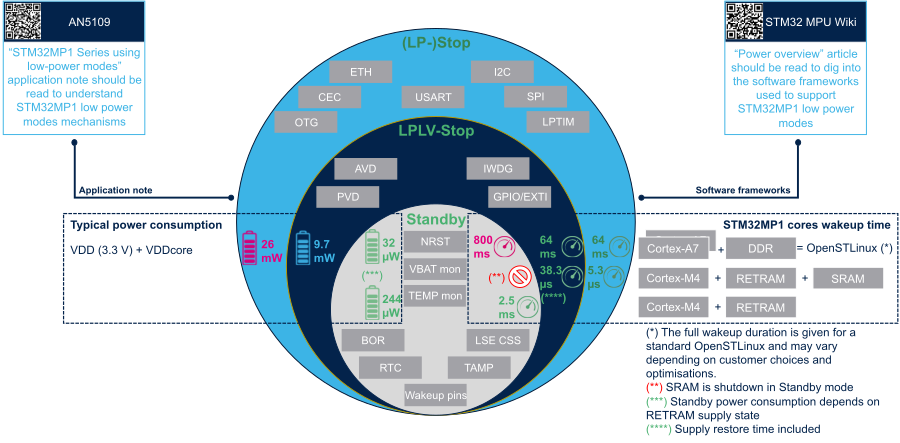
For each supported low power mode (described in the AN5109), the figure below shows:
- The peripherals that can be used as wake up sources (in grey boxes)
- The STM32MP15 typical power consumption (on the left)
- The system wake up times in various configurations (on the right)