1. Introduction
The STM32 Motor-control (MC) Software Development Kit (SDK), is part of the STMicroelectronics motor-control ecosystem. It includes:
- ST MC FOC firmware library for permanent-magnet synchronous motor (PMSM) field-oriented control (FOC)
- ST MC 6-step firmware library
- ST Motor Profiler
- ST Motor Pilot
- ST MC workbench software tool, a Graphical User Interface (GUI) for the configuration of MC SDK firmware library parameters
This document explains how to use the ST MC motor-profiler software tool included with this MC SDK.
2. General information
The ST motor-profiler software tool provides an easy and friendly way to find profiled information for user custom motor and save it as user motor.
The ST Motor Profiler runs on a PC system using Windows® OS and requires a USB type-A connector.
Please, refer to the STM32 MC SDK release note to get all information about the ST Motor Profiler usage possibilities.
The ST motor-profiler software tool can be used to identify the main PMSM characteristics, which are further transferred to the ST MC Workbench.
3. Launch the ST Motor Profiler
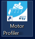
Launch the “ST Motor Profiler” software tool by clicking either its icon (Cf. Figure 1) or either running directly from the installation folder.
The user can run the “ST Motor Profiler” software tool also from the dedicated link button from the ST Motor Control Workbench GUI (Cf. Figure 2).
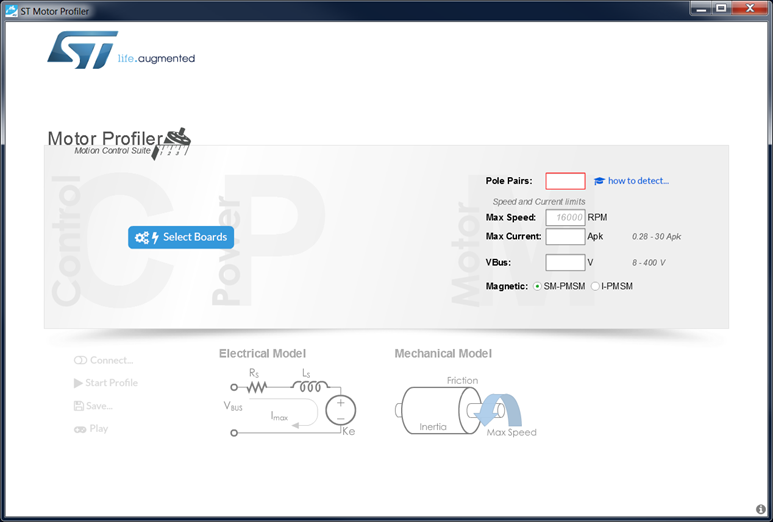
Then, the ST Motor Profiler starts up a GUI window as shown in Figure 3.
4. Configure the hardware setup
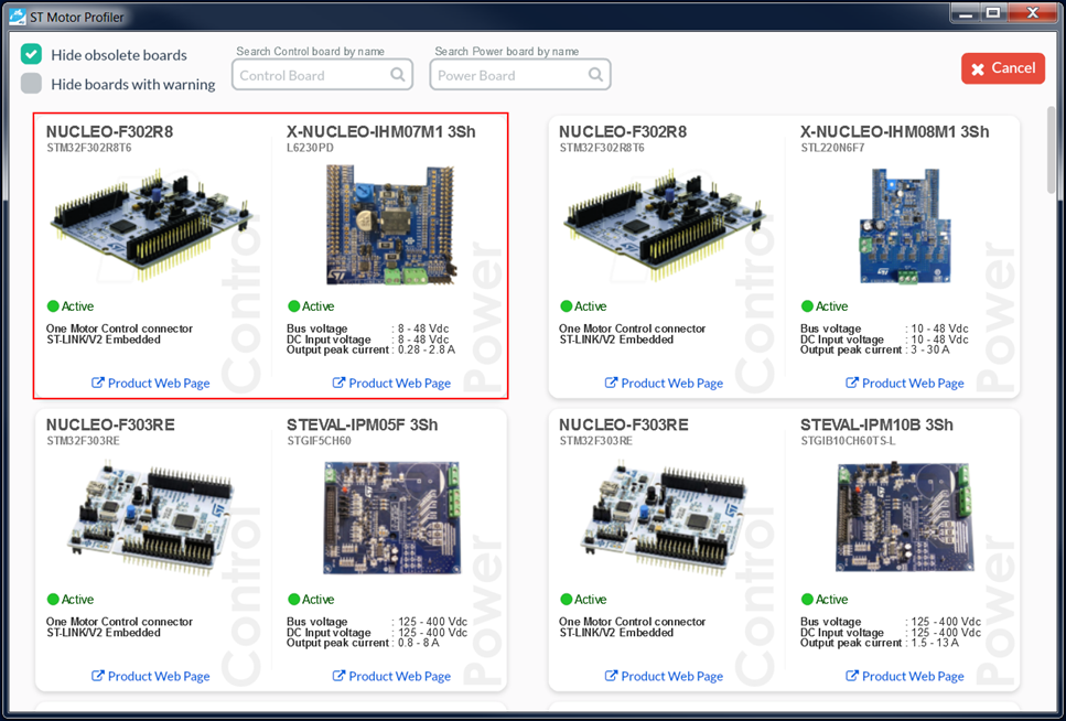
Click on the “Select Boards” button to display the list of supported boards (Cf. Figure 3), then choose the ST application board setup. Note that the ST motor-profiler software tool can be used only with the ST hardware setup listed there. Figure 4 presents an example from this list.
Just click on the ST hardware setup to select it, thus configure the ST motor-profiler software tool.
As an example, Figure 4 shows the P-NUCLEO-IHM001 selection.
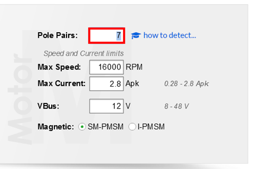
Then, complete the parameter fields with motor information:
- The number of pole pairs inside the motor (mandatory field);
- The max speed of the motor (optional field);
By default, the ST motor-profiler software tool looks for the maximum allowed speed matching the motor and the hardware setup used.
- The max current admissible by the motor (Optional field);
By default, it is the maximum peak current deliverable by the hardware setup.
- The nominal DC bus voltage used by the hardware setup (optional field);
By default, it is the power supply stage as either the bus voltage for low-voltage applications (DC voltage), or either the √2VACrms for high-voltage applications (AC voltage).
- The magnetic build-in type (mandatory field);
By default, it is the SM-PMSM with is selected.
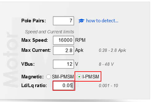
- The Ld/Lq ratio (mandatory field) only in the case of I-PMSM build-in (Cf. Figure 6).
Figure 5 provides example values for the BR2804-1700KV-1 motor provided with the P-NUCLEO-IHM001 hardware setup.
5. Connect to the hardware setup
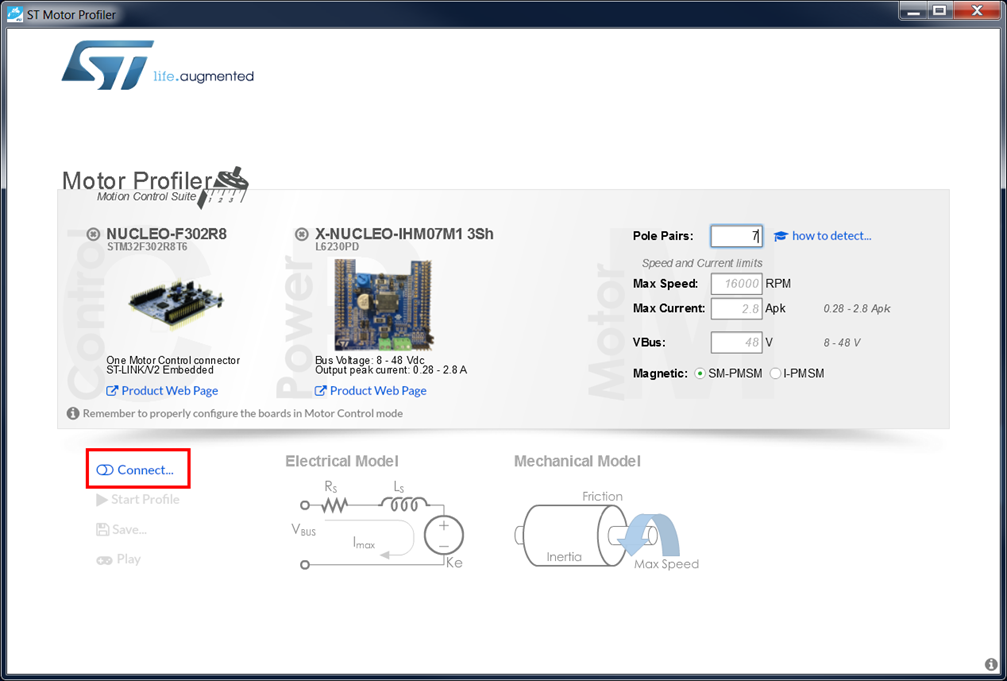
When the ST Motor Profiler is configured, click on the “Connect” button (Cf. red area in Figure 7).
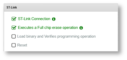
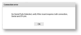
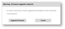
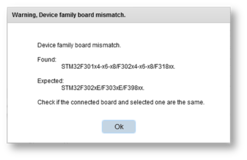
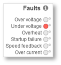
Then, depending on the hardware setup history, a status window appears as shown in Figure 8. In case of a problem, a troubleshot message window pops up (Cf. Table 1) to support a recovery action.
When successfully connected to the hardware setup, the “Start Profile” button shall appear as surrounded in Figure 9.
6. Profile the motor
Click on the “Start Profile” button as surrounded in Figure 9 to profile the motor.
First, the electrical parameters are identified, then the Mechanical ones. In the case of Over-Current fault detection, the profiling is restarted with a reduced current. When profiling is completed, all the motor measurements are shown in green or orange colors (Cf. Figure 10) depending on the relative accuracy. When red color is used, please check the hardware setup and restart the motor profiling sequence.
7. Save the profiled motor
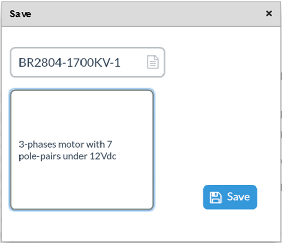
Click on the “Save…” button (Cf. Figure 10) to store the motor measurements for later usage with the ST MC workbench software tool.
Figure 11 shows the saving window in that case, then the motor information may be provided:
- Naming of the profiled motor;
Provides with details about the profiled motor.
8. Play with the motor
Click on the “Play” button (Cf. Figure 10) to spin the just profiled motor.
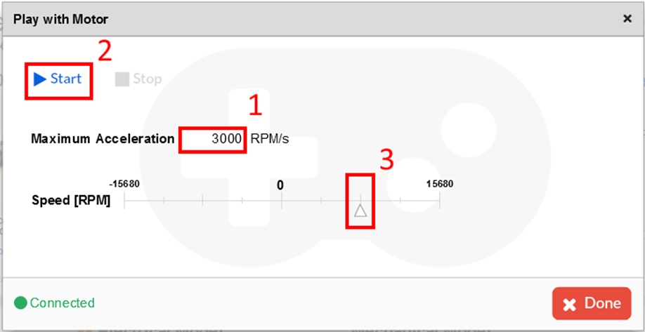
Figure 12 shows the spin control window. Preset the maximum acceleration and click on the “Start” button to activate the motor control. Then, select the “Speed [RPM]” with the cursor.
Figure 13 presents how to stop properly playing with the motor.
9. End the ST Motor Profiler
Click on the “Disconnect” button (Cf. Figure 10) to stop properly the ST motor-profiler software tool, then close the window using the upper-right cross icon.
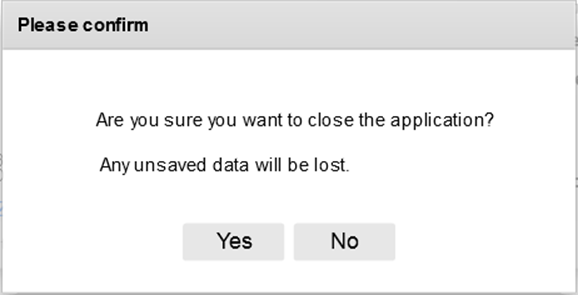
If the user forgets to save his motor parameters, he selects the “No” button (Cf. Figure 14), clicks on the “Connect” button (Cf. Figure 7), and saves his motor parameters. However, clicking on the “Yes” button loses the unsaved motor parameters and closes the ST motor-profiler software tool.
[[Category:Motor Control]]
