1. Overall description
This page describes the functioning of the smart home mesh solution (Zigbee-Bluetooth® LE) and how to handle it.
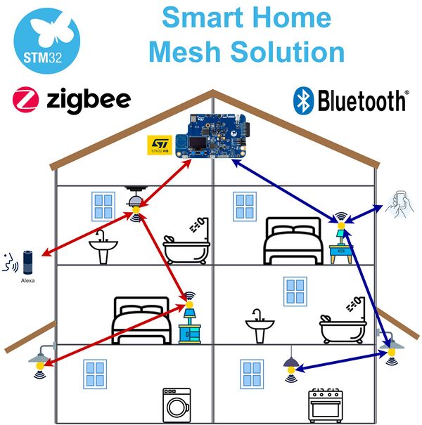
This project demonstrates the STM32WB application capabilities using Zigbee-Bluetooth® LE mesh solutions in a smart home application, with the additional use of a smartphone and the Amazon virtual assistant (Alexa).
Zigbee and BLE (Bluetooth® Low Energy) mesh connects multiple Zigbee and BLE devices with mesh networking capability for IoT (internet of things) solutions.
| Zigbee BLE mesh illustration |
|---|
Mesh network has a many-to-many topology, with each device able to communicate with every other device in the network.
The BLE mesh communication is done using messages relayed by devices, which are part of the mesh network (called nodes). In this way, the end-to-end communication range is extended far beyond the radio range of each individual node.
A quick description of the BLE mesh vendor model is available in the ST BLE-Mesh application note[1].
| Project overview |
|---|
To realize this project, seven STM32WB5MM-DK Discovery kits[2] were used. In addition, one Amazon Alexa assistant and two Android or iOS phones have to be included.
The three Zigbee nodes, the three BLE nodes, and the BLE/Zigbee bridge node can be controlled with the Zigbee hub built-in to the new Echo Show 10 Alexa assistant, or with a smartphone for the BLE mesh part.
2. Demonstration setup
2.1. Device requirement
The required material to set up the demonstration is as follows:
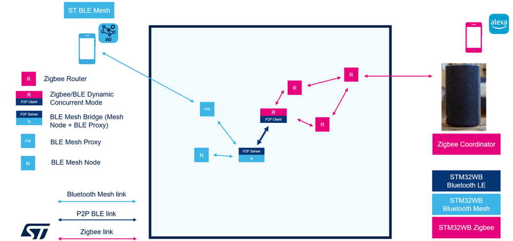
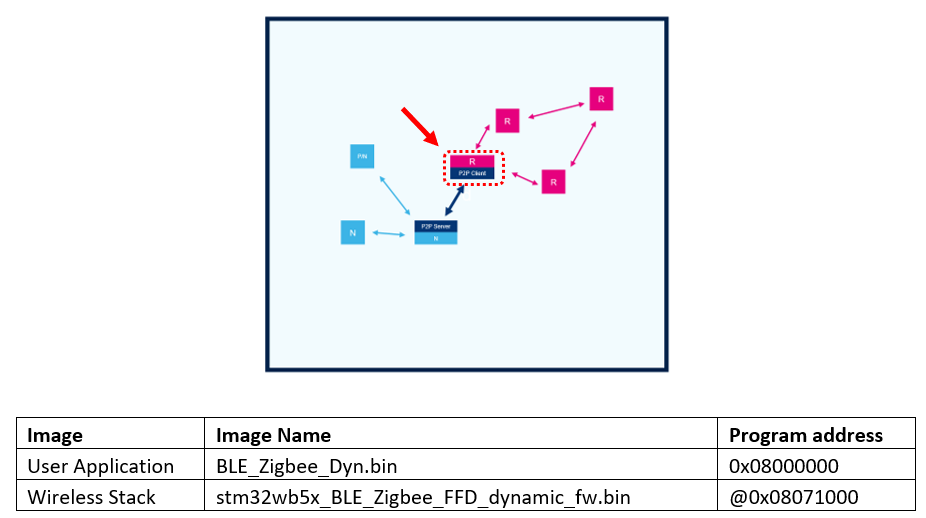
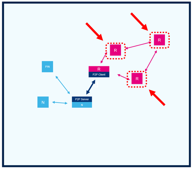
- Seven STM32WB5MM-DK Discovery kits[2]: three as Zigbee routers, one as BLE mesh proxy, one as BLE mesh node, one as BLE mesh bridge, and one as Zigbee/BLE dynamic concurrent mode router.
- One Amazon Alexa Echo assistant.
- One smartphone to use the Alexa app using an Alexa account.
- One smartphone with ST BLE Mesh application
2.2. Network setup
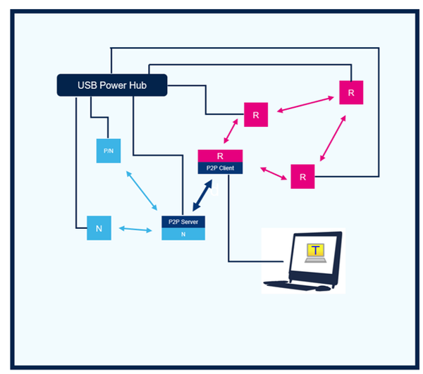
The different nodes are the following:
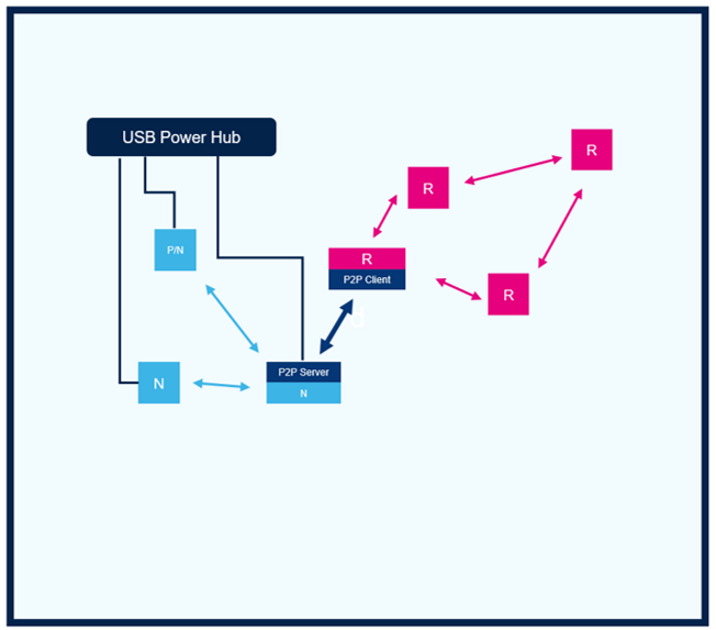
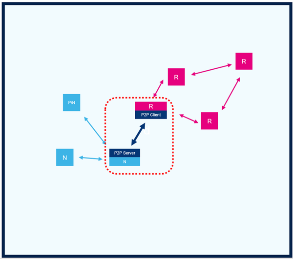
• 3x BLE mesh node o 1x BLE mesh bridge – GATT server proxy that connects to the Zigbee/BLE bridge GATT client o 1x BLE mesh proxy node – Connects with the smartphone app, "ST BLE Mesh" o 1x BLE mesh node – Generic BLE mesh node
• 1x BLE/Zigbee bridge node – BLE GATT client and Zigbee server node
• 3x Zigbee nodes – Zigbee server router node
| Zigbee BLE smart home network |
|---|
3. Device programming
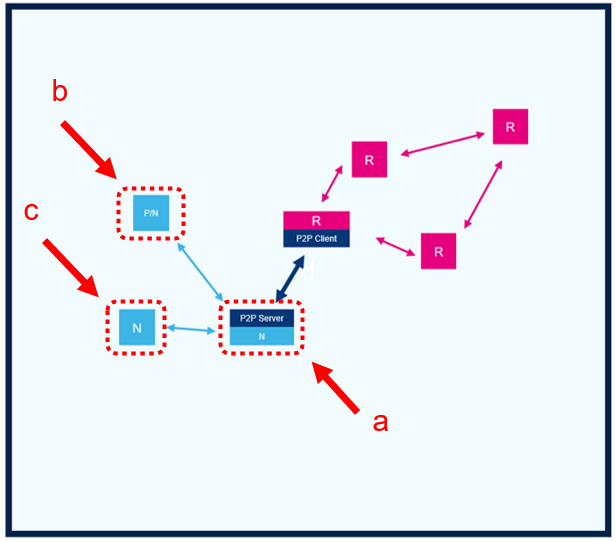
Three STM32WB5MM-DK boards are used as BLE mesh nodes.
a. 1x STM32WB5MM-DK as the BLE mesh bridge
b. 1x STM32WB5MM-DK as the BLE mesh proxy node
c. 1x STM32WB5MM-DK as the BLE mesh node
| Zigbee BLE smart home network |
|---|
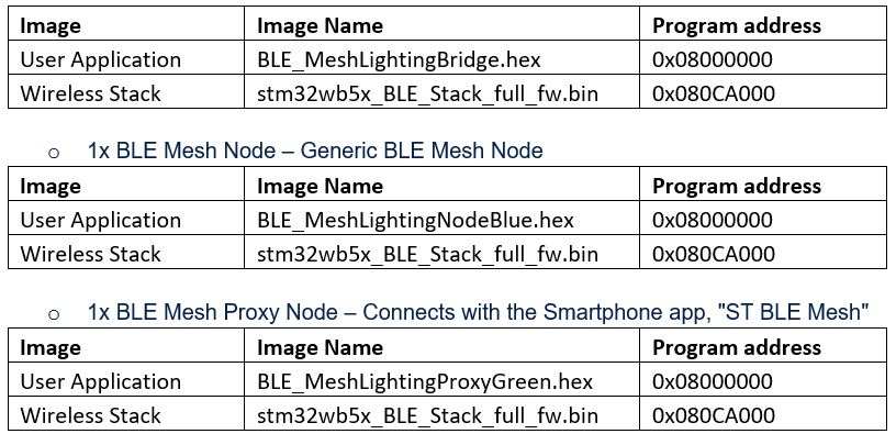
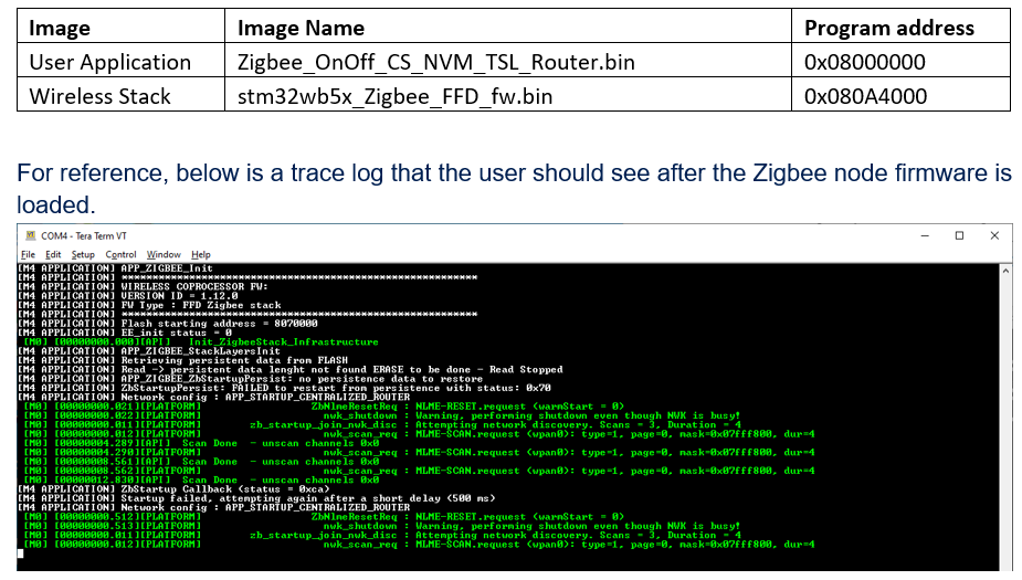
With CubeProgrammer, program the following firmware images on the respective STM32WB5MM-DK being used. But before programming these, perform a flash mass erase on each of the boards.
• 3x BLE mesh node
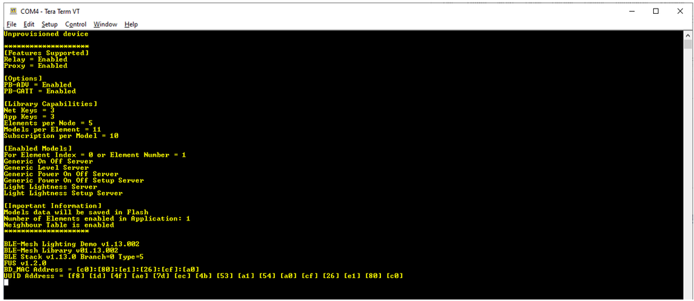
For reference, below is a trace log that the user should see after the BLE mesh firmware is loaded on the BLE mesh nodes.
• 1x BLE/Zigbee bridge node – BLE GATT client and Zigbee server node
For reference, below is a trace log that the user should see after the BLE/Zigbee bridge firmware is loaded.
• 3x Zigbee nodes – Zigbee server router-node
4. BLE mesh node setup (provisioning)
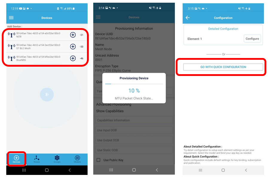
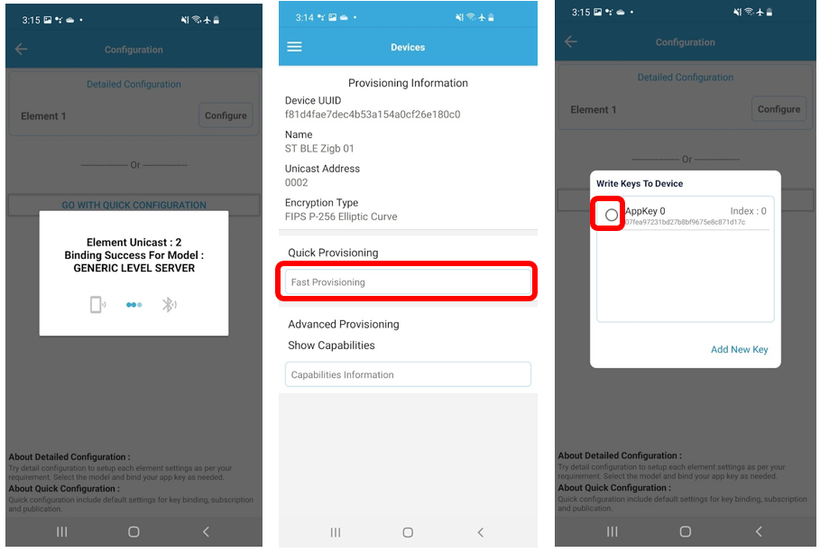
Provision the three BLE mesh nodes from the iOS or Android ST BLE Mesh app following the procedure below for all:
• BLE mesh bridge
• BLE mesh proxy node
• BLE mesh node
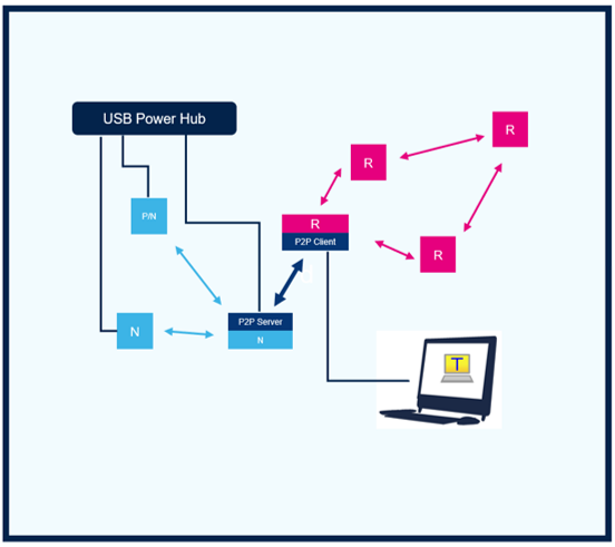
Start by powering on the boards from a USB power hub.
ST BLE
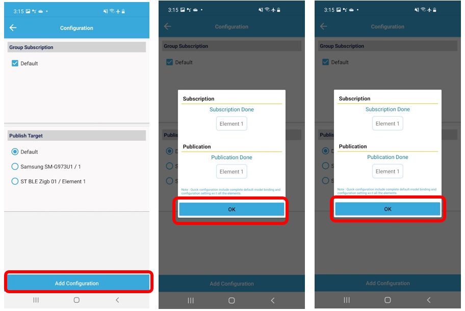
Start the provisioning process from the ST BLE Mesh app.
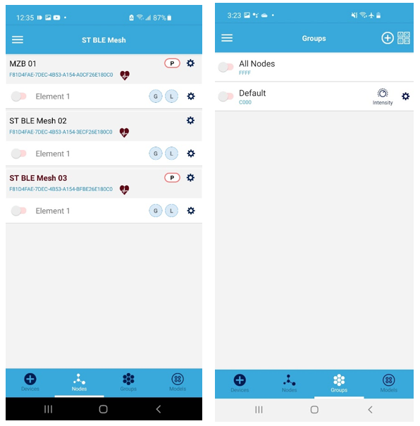
When the three devices are provisioned, they appear under the devices window of the app.
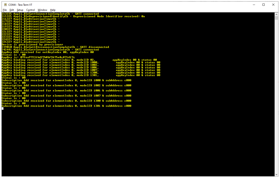
For reference, below is the trace log (115200 baud rate) from the BLE mesh nodes during provisioning.
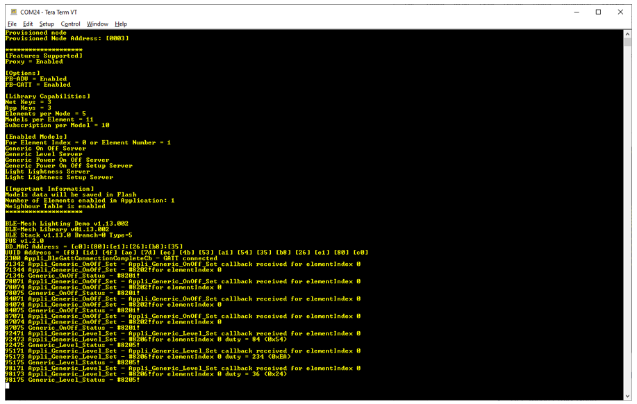
For reference, below is the trace log (115200 baud rate) from the BLE mesh proxy node in operation when being connected and controlled by the smartphone ST BLE Mesh app.
5. Zigbee/BLE bridge node setup (provisioning)
It is important that the Zigbee/BLE bridge node setup is performed after setting up the BLE mesh nodes. Indeed, the Zigbee/BLE bridge is to connect to the BLE mesh bridge proxy node. Also, it is recommended to perform this step before running the rest of the Zigbee nodes, to prevent the Zigbee nodes from interfering.
Note that it is critical that the BLE/Zigbee bridge node is connected and powered by a PC to connect to the board from a serial terminal (baudrate 115200) to see the trace logs, since the user has to visually verify if the BLE and Zigbee connections are established successfully. Note that this is the most complex step in the demo!
Note that while all other Zigbee and BLE mesh nodes are powered from a USB power hub, the “BLE/Zigbee Bridge” need to be powered from a PC or equivalent that permits you to run a serial terminal to view its traces.
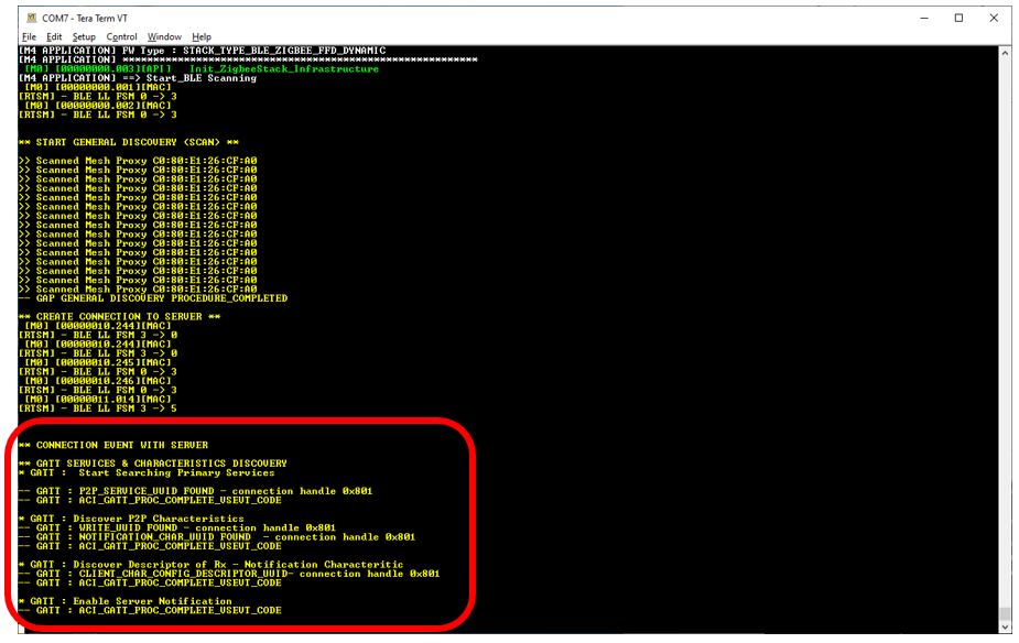
Power on “Zigbee/BLE Bridge” board, and it comes up in BLE client mode and begin scanning for the BLE mesh proxy server device. It should discover it and connect to it automatically, as shown in the trace log below. However, if the GATT service and characteristic discovery fail and do not show as highlighted in the trace below, then the user should retry by resetting the board to retry the connection.
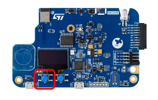
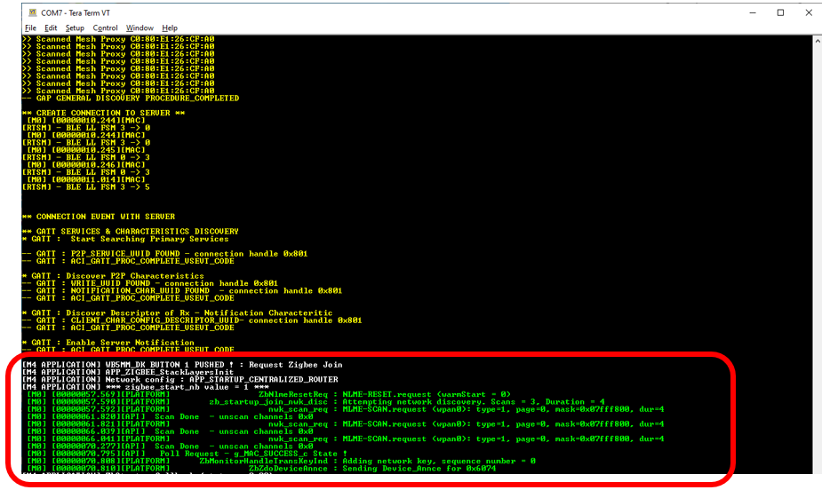
Once the BLE client establishes the connection with the BLE mesh proxy server, the user should then manually start the Zigbee network scan, by pressing the user button 1 on the board to start the Zigbee network scan and join the request.
The user button 1 press action shows up in the log as highlighted below.
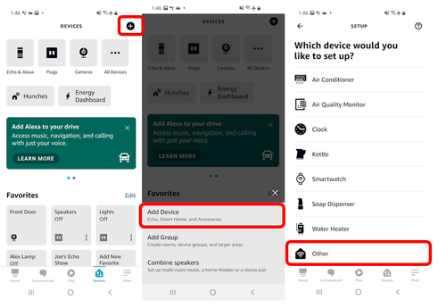
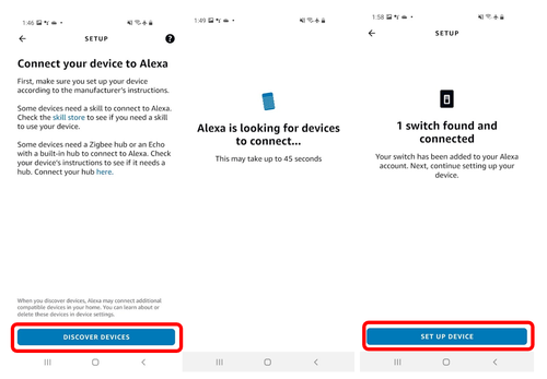
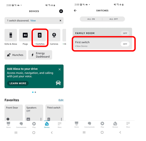
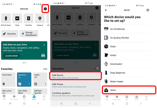
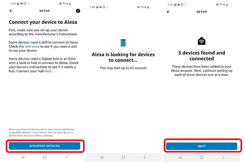
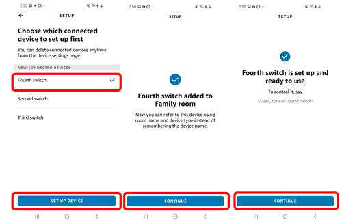
The user can now command Alexa to start the device discovery with one of two methods:
1. Using the Amazon Echo’s voice assistant by saying “Alexa, discover devices”
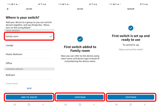
2. Using the Alexa app, as shown below:
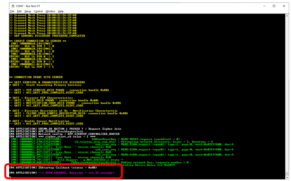
From the trace log, the user should verify that the device joined the network successfully by verifying the highlighted trace.
If this trace is not displayed, the user should reset the “Zigbee/BLE bridge” board and retry the process.
Note that the Zigbee part in the “Zigbee/BLE bridge” device does not support data persistence. Therefore it must be added to the Alexa Zigbee network after every power cycle (in other words it repeats the cycle ).
Note: In the event that the BLE/Zigbee bridge is power cycled or reset, the process to connect to the BLE mesh and Zigbee networks, described in section 6, must be repeated.
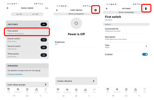
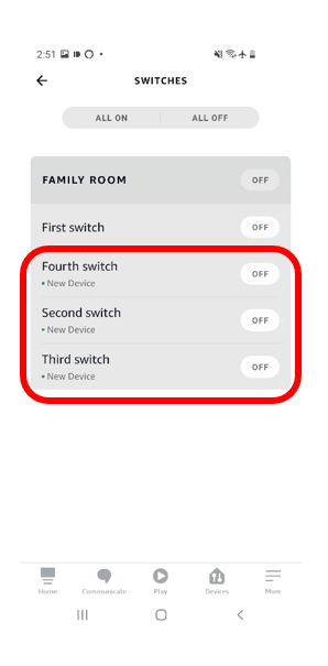
The previous added device need to be deleted from the Alexa app, as shown below.
6. Zigbee node setup (provisioning)
Power on reset of Zigbee nodes by connecting these to a USB power supply (or PC).
Unlike the Zigbee/BLE bridge, the Zigbee nodes start the network scan automatically after power on. Thus, no need for any user button to be pressed.
Next, command Alexa starts the device discovery with one of two methods:
1. Using the Amazon Echo’s voice assistant by saying “Alexa, discover devices”
2. Using the Alexa app, as shown below:
If the board is connected to a PC, the user can connect to the board using a serial terminal (baudrate 115200) to see traces. Ultimately, this step is optional while useful when troubleshooting.
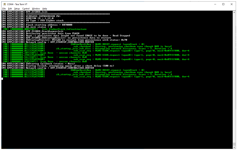
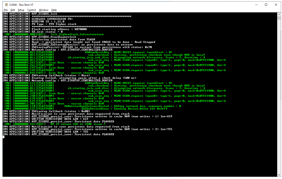
For reference, Log should appear as shown below when scanning for the network to join.
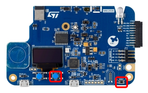
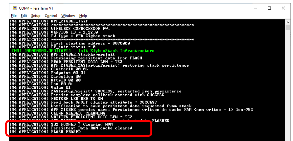
When the user is setting up the Zigbee nodes for the first time, the user should press the user button 2 to clear any persistent data that could be stored in the flash memory.
However, once the Zigbee nodes have joined the network once, the user should not clear the persistent data to avoid having to repeat the provisioning process from section 6.
Then, press the RESET (B3) button to restart the application. Once the node has joined the Zigbee network, the network information is stored in the flash memory (called persistent data). This avoids having to go through this network join procedure again, even after the boards have been power cycled. The persistent data remains unless the user presses the user button 2.
7. Demo operation
For demo operation instructions, watch the Bluetooth® LE Mesh and Zigbee Smart Home Solutions video
8. References
