Target description
The purpose of this article is to explain how to proceed step by step to generate a bootpath using STM32CubeMX.
The example below will show how to configure and provision a bootpath for an OEMiRoT with the initial code generation for a secure or non secure user application.
Read the Secure Boot STM32H5 How to Introduction article before starting the practical example described below.
More technical details before getting started are also available in the following articles:
- Introduction article: Introduction to Secure boot and Secure firmware update
- Specific STM32H5 bootpaths article: Secure Boot for STM32H5
- OEMiRoT article OEMiRoT-OEMuRoT for STM32H5
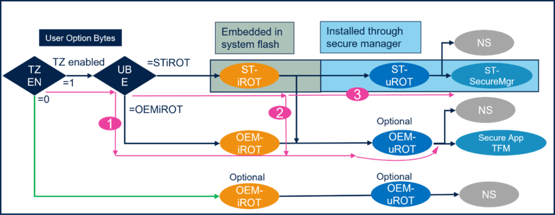
The How to start described in this article is using the bootpath number 1 of the figure below.
Prerequisites
To follow the example described below, the following items are required:
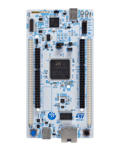
- NUCLEO board: NUCLEO-H563ZI
- Tools:
- STM32CubeMX_6.9.0 or later (see STM32CubeMX ST web page[1])
- IAR Embedded Workbench rev 9.20.1 or later
- STM32CubeProgrammer rev 2.13.0
Note:
- The STM32 Trusted Package Creator (TPC) is automatically installed during the STM32CubeMX installation. The dedicated version of TPC for STM32CubeMX is installed in the STM32CubeMX/utilities folder.
- The latest STM32Cube_FW revision is installed through STM32CubeMX (see appendix).
- If needed, set the windows environment variable (see appendix). It is required in case the H5 doesn’t appear in the “Access to MCU selector” of the STM32CubeMX.
1. OEMiRoT_Boot firmware compilation
Before starting the STM32CubeMX project configuration, it is advised to compile the project OEMiRoT_Boot.
OEMiRoT_Boot is executed in HDPL1 in user flash memory. It perform authenticity and integrity checks on the user application.
It also configures the number of user application and images.
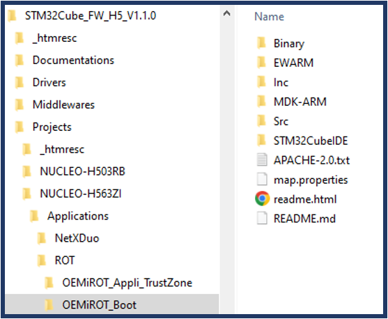
This project is located in STM32CubeH5 firmware: C:\STM32Cube_FW_H5_V1.1.0\Projects\NUCLEO-H563ZI\Applications\ROT\OEMiROT_Boot
Open the OEMiRoT_Boot project with the preferred IDE (EWARM/MDK-ARM or STM32CubeIDE) and rebuild all files.
Refer to OEMiRoT STM32H5 How to Introduction for more informations.
2. Setting the STM32CubeMX project
Launch STM32CubeMX
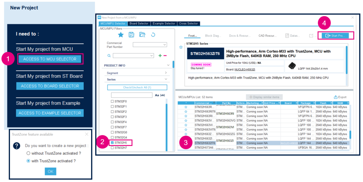
- Click on Access to MCU selector. It's easier for this example to only enable the GPIOs needed. Thus, it's advised to use the MCU selector instead of the board selector.
- Select STM32H5 series and select the device used in the NUCLEO_H563.
- Click to start the project.
- Enable the TrustZone as shown in the figure 1 for the OEMiRoT bootpath that requires it.
Set the STM32CubeMX project:
- Type the name of the project. The related folder will be created.
- Chose the folder for this project. it is recommended to avoid long path.
- Check that Secure Project and Non Secure Project are ticked (setting by default).
- Select the toolchain. For this example, EWARN is used.
- File -> Save Project -> the project folder (if not already existing) and the STM32H563_OEMiROT.ioc file is created.
OEMiRoT_Boot project location
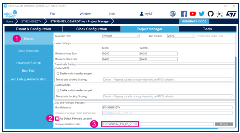
If you want to use another repository for the STM32CubeH5 MCU Package than the default STM32CubeMX folder, you can define it in
Project Manager--> Project Tab-->MCU and Firmware Package:
- Uncheck Use Default Firmware Location.
- Define the path you want to use in Firmware Relative Path.
3. GPIO configuration
For this proposed example, three GPIOs need to be configured for the discovery board:
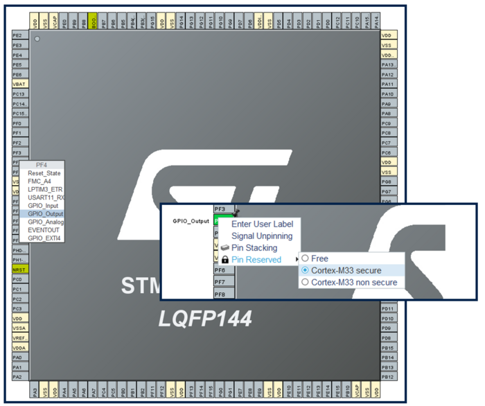
- PF4 for the orange LED used in the secure user application code.
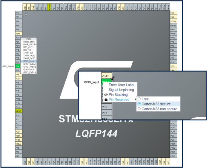
- PC13 for the blue user button used in the secure user application code.
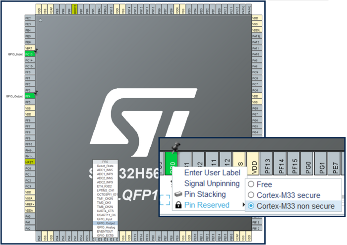
- PB0 for the green LED used in the non secure user application code.
In the STM32CubeMX, select the Pinout & Configuration window.
To configure the GPIO for the orange LED, proceed as follow:
- Left click on PF4 and select GPIO_Output -> A push pull output needs to be configured to drive an LED.
- Right click on PF4 and select Cortex-M33 secure. This GPIO is then assigned to the secure user application code.
To configure the user blue button, proceed as follow:
- Left click on PC13 and select GPIO_Input.
- Right click on PC13 and select Cortex-M33 secure. This GPIO is then assigned to the secure user application code.
To configure the GPIO for the green LED, proceed as follow:
- Left click on PB0 and select GPIO_Output -> A push pull output needs to be configured to drive an LED.
- Right click on PB0 and select Cortex-M33 non-secure. This GPIO is then assigned to the non secure user application code.
- Select GPIO: the summary of the settings is displayed as shown in the figure below.
4. Configure the OEMiRoT bootpath
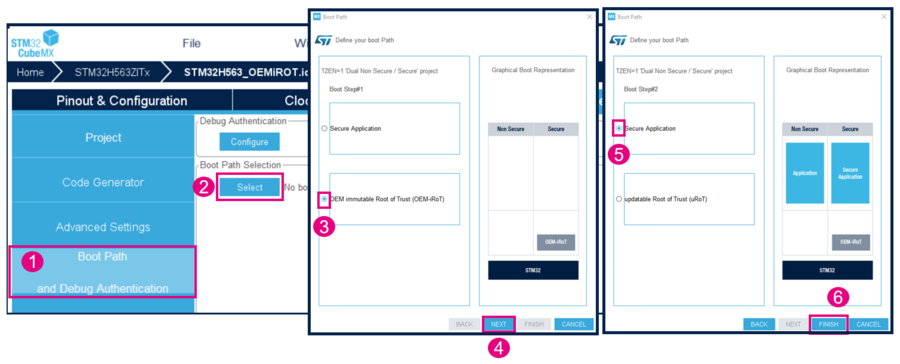
To configure the bootpath number 1 of the figure 1, proceed as follow:
- Click on Boot Path and Debug Authentication.
- Click on Select.
- Select the OEMiRoT. The TrustZone activation has already been chosen. This selection is defining the UBE option byte. However, the setting of this option byte doesn't need any input from the user.
- Click on Next.
- Select "Secure Application". Since there is no uROT for this example, there is no second boot stage.
- Click on Finish.
Note: Depending on the STM32CubeMX version, the Debug Authentication Configure button can't be selected before completing the OEMiROT bootpath configuration.
OEMiRoT_Boot firmware
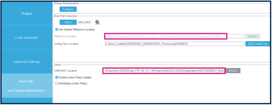
You can view the OEMiROT_Boot firmware path in Boot path and Linker tabs.
This firmware is located by default in the STM32CubeH5 MCU Package installed through STM32CubeMX.
If necessary, the OEMiRoT_Boot might be compiled by the user during the provisioning.
If you want to change the OEMiRoT_Boot firmware location please refer to paragraph 2 Setting the STM32CubeMX project, then OEMiRoT_Boot project location. In fact if this firmware is not located closed to root of C:/ errors can occur during compilation.
OEMiRoT configuration
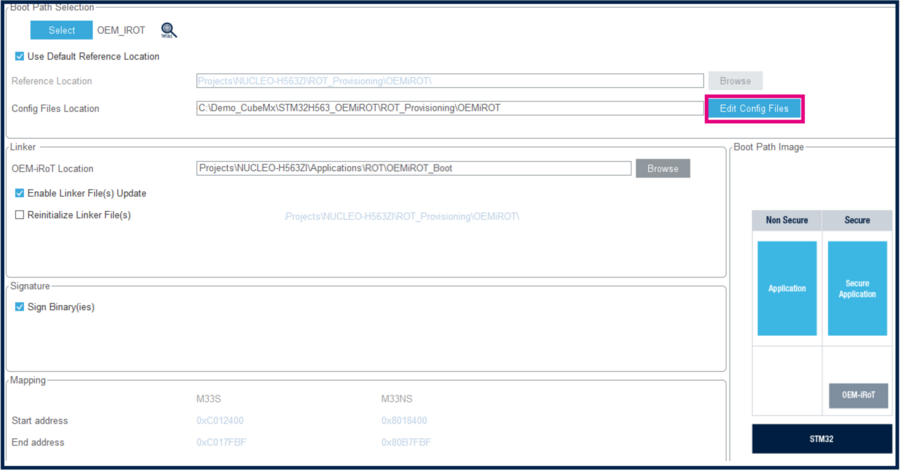
In the Project Manager window, select Edit Config as shown in the figure below.
It will automatically open STM32 Trusted Package Creator (TPC).
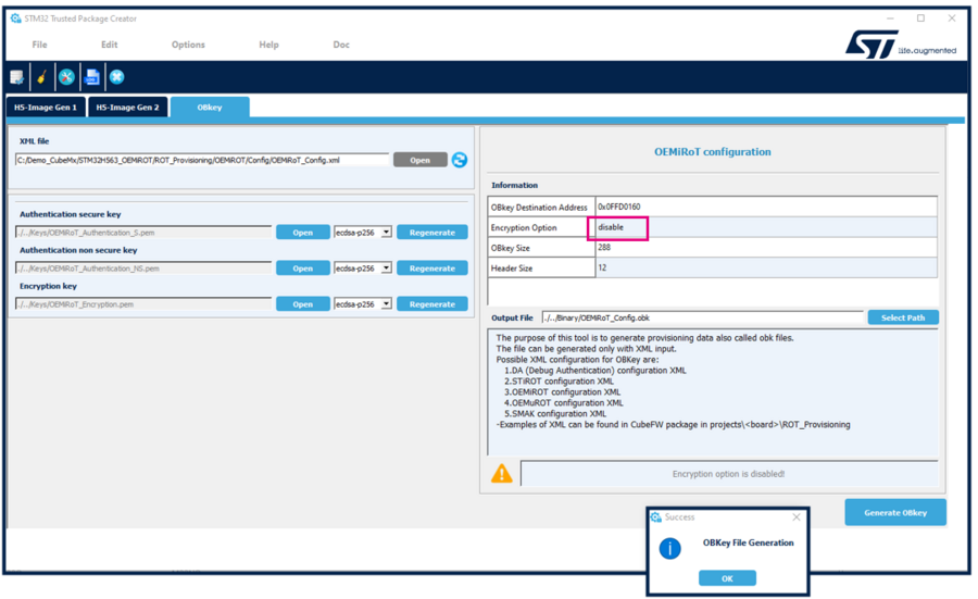
The following window is displayed.
- Generate the OBKey file:
Notes:
- For the STM32H563 devices, the Encryption option is disabled. This option is enabled on STM32H573 crypto devices only.
- The figure above shows the path where the OEMiROT_Config.xml file is located. This file contains all the configuration parameters for the OEMiRoT.
- The configuration of the OEMiRoT is defined in the OEMiRoT_Boot firmware. During the provisioning, the download area is used to store the encrypted user application that is decrypted by the OEMiRoT, and installed in the execution area. Refer to the OEMiRoT STM32H5 How to Introduction article.
- For a commercial product, it's important to regenerate the authentication keys and the encryption key.
As mentioned above, for this example, no other update of the default configuration is needed.
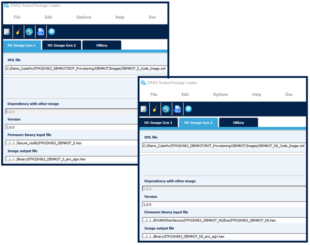
Select H5-Image Gen 1 as shown in the figure below. No modification needs to be done in this window, but some explanations need to be provided:
- The OEMiRoT_S_Code_Image.xml file contains the settings needed to generate the images.
- Two paths are indicated for binary files:
- During the code compilation using the IDE, a binary file containing the compiled secure application is created.
- The IDE will also perform a postbuild command to generate from this binary input files a single encrypted and signed binary image.
- Note: The mentioned paths above are updated by STM32CubeMX and must not be modified.
For the H5-Image Gen 2, the explanation for the non secure images generation with the file OEMiRoT_NS_Code_Image.xml are the same.
- Close STM32 Trusted Package Creator.
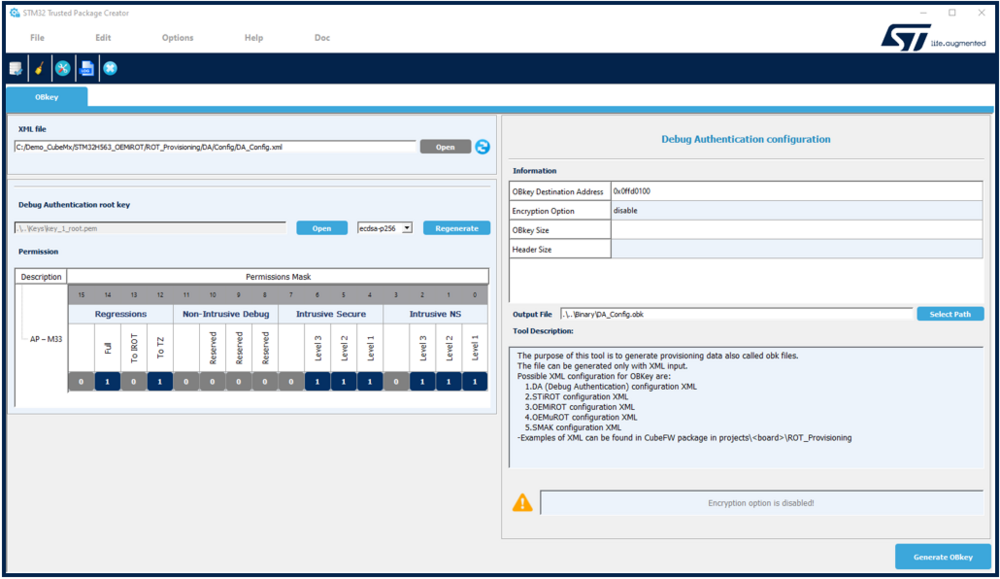
5. Debug Authentication configuration
Refer to the Debug Authentication for STM32H5 article for more details.
A default configuration file (fully functional) and a related OBKey file are provided through the STM32CubeFW.
To customize the Debug Authentication, proceed as follow:
- In STM32CubeMX -> Project Manager -> Select: Debug Authentication Configure.
- The STM32 Trusted Package Creator is launched (TPC installed together with STM32CubeProgrammer) and the DA_Config.xml file is automatically open.
- The "key_1_root" key is needed to reopen the device or to perform a regression. To protect the user developed application, this key needs to be regenerated. If regenerated, it's important to not lose this new key.
- Don't regenerate the key for this example.
- The permission mask is set to allow all possible regressions and debug openings in the secure and non secure user application.
See Debug Authentication STM32H5 How to Introduction article for more details.
This permission mask, called the SOC mask, is stored in the device during the provisioning process.
The owner of the root key has then the defined privileges to perform a regression or open the debugger according set permissions.
- Close the STM32 Trusted Package Creator.
6. Initial Code Generation and modification
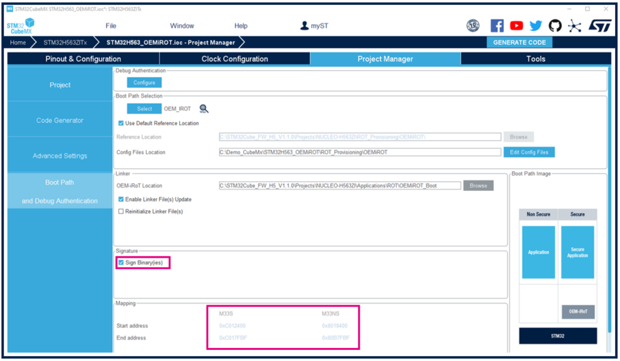
Select Project Manager in STM32CubeMX.
- Ensure Sign Binaries is selected. At each user application code compilation using the IDE an encrypted and signed binary is created containing both secure and non secure user application (compilation -> postbuild command).
- Note that start and end address are indicated for the secure and non secure according to the OEMiRoT configuration.
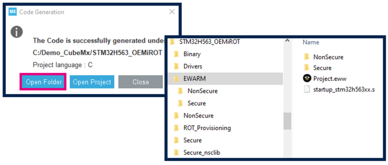
- Click on Generate Code.
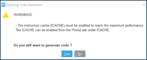
- The following warning message may appear. Click yes to generate the code.
- Or if the instruction cache needs to be enabled, select in the Pinout & Configuration tab ICache located just below the GPIO configuration.
- Open the generated user application.
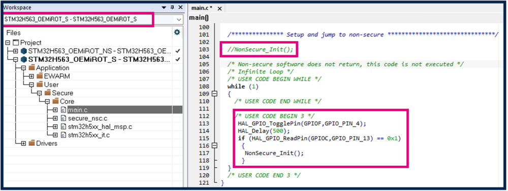
Open the secure user application code.
- Comment out NonSecure_Init() for the jump into the non secure user application code (replaced with the code below).
- Insert the following code as shown in the figure below.
HAL_GPIO_TogglePin(GPIOF,GPIO_PIN_4);
HAL_Delay(500);
if (HAL_GPIO_ReadPin(GPIOC,GPIO_PIN_13) == 0x1)
{
NonSecure_Init();
}
This code will make the orange LED blinking with the chosen delay, showing that the secure user application is executed.
If the user blue button is pushed, the jump in the non secure code is done through the Non-Secure_Init .
- Compile the code using the IDE (Project -> Rebuild all).
- Note: The secure code needs to be compiled first (before the non secure code).
Open the non secure user application.
- Insert the following code as shown in the figure below.
HAL_GPIO_TogglePin(GPIOB,GPIO_PIN_0);
HAL_Delay(800);
This code will make the green LED blinking with the chosen delay, showing that the non secure user application is executed.
- Compile the code using the IDE (Project -> Rebuild all).
Two binaries are created as shown in the figure below:
- The binary obtained after the signature and encryption of the binary of secure application.
- The binary obtained after the signature and encryption of the binary of non secure application.
Both binaries have been generated through the automatically called postbuild command.
7. Device Provisioning
For the device provisioning, the OBKey files generated previously are used to configure the device OEMiRoT accordingly, and to configure the Debug Authentication according to the permission mask.
The encrypted and signed binary is uploaded in the download area defined during the OEMiROT_Boot configuration.
The OEMiRoT_Boot firmware verifies the authenticity, decrypt, and install the secure and non secure user applications in the execution area defined during the OEMiRoT_Boot configuration.
The provisioning script automatically calls the STM32CubeProgrammer Command Line Interface (CLI).
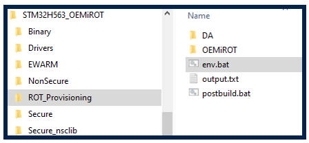
It's important that the path to the STM32CubeProgrammer is correct in the env.bat file. Check and update as shown in the figure below.
Don't modify the path to the STM32 TrustedPackageCreator included in the STM32CubeMX.
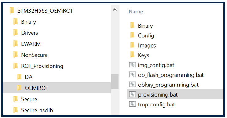
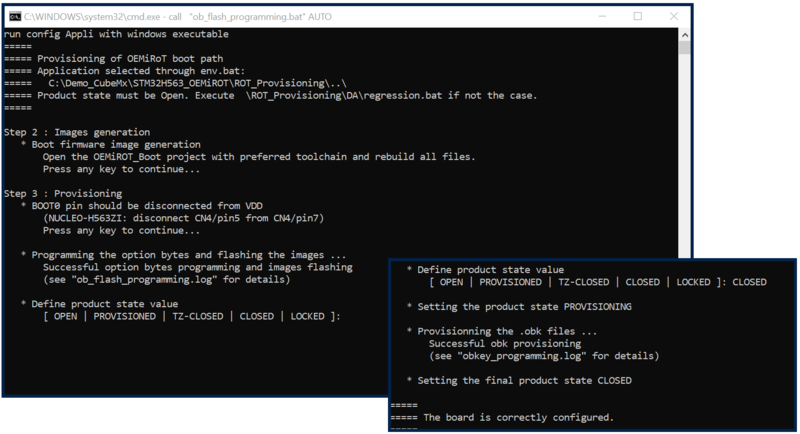
The provisioning of the device is done using the provided provisioning script.
- Connect your board with the USB cable (USB STLink connector).
- Double click on the provisioning.bat shown in the figure below.
- The provisioning step 1 is the configuration.
- The OEMiRoT configuration setting done previously (generation of the related OEMiRoT_Config.obk file).
- The DA configuration setting done previously (generation of the related DA_Config.obk file).
- The provisioning step 2 is the image generation.
- If it has not been done at the beginning: OEMiRoT_Boot firmware compilation, you have to open the OEMiRoT_Boot project with the preferred IDE (EWARM/MDK-ARM or STM32CubeIDE) and rebuild all files.
- The user application code image generation has been done previously during the compilation and the postbuild.
- The image generation is not applicable for this example -> type any key.
- The provisioning step 3 is the board provisioning.
- Before typing any key, check the indicated boot switch position.
- The STM32H5 device provisioning is executed, the configuration is stored, and the user application codes are installed.
- Note: For Linux and Mac operating systems, the end users may have to change manually the attribute of .sh scripts to executable.
- The last step is the product state setting. For this example, the device is set in CLOSED.
- After the message that the board is correctly configured, the script can be closed.
See Introduction to Silicon device life cycle and Debug Authentication articles for detail explanations.
8. Code execution
- Press the black reset button, the orange LED is blinking, showing that the secure user application is executed.
- Press the blue button, the green LED is blinking showing that the jump to the non secure application has been successful and the code is executed.
9. STM32CubeProgrammer, discovery command
- Start the STM32CubeProgrammer and try to connect.
- The error message below is displayed because the device has been set in CLOSED state, and the debugger can't be connected even to see the non secure user application code.
- To reopen the debugger, a Debug Authentication is needed, and the opening can only be done by the owner of the root key.
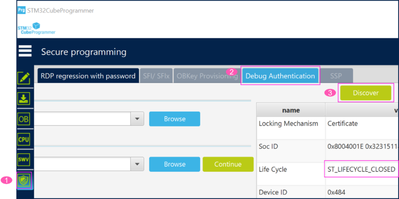
The product state can be seen using the Discovery command (see figure below):
- In STM32CubeProgrammer, click on the shield icon.
- Select Debug Authentication.
- Click on Discover, the lifecycle CLOSED is displayed.
An example on how to reopen the debugger, view the code, and attach an IDE to perform a step by step application execution is shown in the chapter 3 of the article How to start with OEMiRoT on STM32H573 and 563–TrustZone enabled.
10. Regression
The regression will remove the user applications and protections.
If the board is not in the OPEN state after completing a hands-on, it is recommended to perform a regression, especially if the root key has been regenerated.
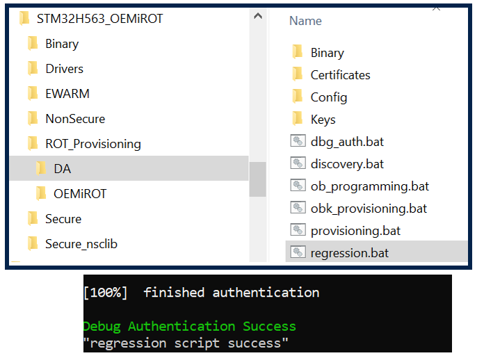
- Double click to start the regression script shown in the figure below.
- The regression is performed automatically. The Debug Authentication is done using the root and using the permission defined during the OEMiRoT configuration.
- Note: For Linux and Mac operating systems, the end users may have to change manually the attribute of .sh scripts to executable.
- It is possible to connect to STM32CubeProgrammer, and see that the debugger is open again, and that the flash has been fully erased.
11. Appendix
11.1. STM32CubeFW installation
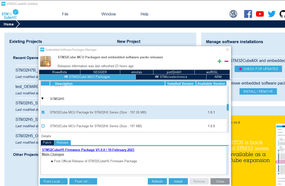
The STM32CubeFW needs to be installed through STM32CubeMX.
- Step 1: the repository folder has to be defined:
- In STM32CubeMx: Help menu -> Updater Settings
- Browse the repository you have chosen for the STM32CubeFW.
- Step 2: STM32CubeFW installation
- In STM32CubeMX, Select Install/Remove
- In the description frame, select STM32H5.
- Select the CubeFW package to install.
- In case you have locally the zip file of the STM32CubeFWH5: it can be installed by drag and drop this file in the description window.
Note: Only STM32CubeMX can install an official STM32CubeFW release.
12. References
