Target description
The first part of the article:
The first part of the article introduces the External Memory Manager and External Memory Loader middleware features in BootFlash/Flashless applications on STM32H7R/H7S and STM32N6 products, in order to:
- Provide an API that allows access to all types of memory.
- Launch an application stored in an external memory.
- Generate an External memory loader file
The second part of the article:
The second part of the article presents a detailed tutorial on the implementation of the External Memory Manager and External Memory Loader middleware functionalities. The article also features a configuration sample utilizing STM32CubeMX, which can be used as a reference to apply these functionalities to:
- Configure the External Memory Manager.
- Configure the External Memory Loader.
- Build a BootFlash application.
Hardware
- STM32H7R/H7S
- STM32N6
Software
- An IDE (IAR Systems®, Keil®, STM32CubeIDE).
- Software tool for STM32 products programming.
Literature
- Getting started with Octo-SPI and Hexadeca-SPI Interface on STM32microcontroller[1]
- Introduction to External Memory Manager and External Memory Loader Middleware for Boot Flash MCU[2]
1. What is a BootFlash product
1.1. Definition
A BootFlash product is a product with a small embedded flash memory for an initial boot step and with an application located in an external memory.
1.2. What is a BootFlash application?
The STM32CubeMx tool provides the ability to create a BootFlash application, which uses the external memory manager and external memory loading middleware, to create a boot system capable of launching an application stored on external memory.
The project structure of a BootFlash application is divided into three different contexts:
- Boot: boot code to run from the internal flash memory.
- Appli: application code to run from the external flash memory.
- ExtMemLoader: code dedicated to generating the External Loader.

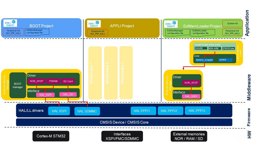
The image below shows the STM32H7Rx/H7Sx application architecture based on the use of External Memory Manager and External Memory Loader middleware.
2. What is a Flashless product
A Flashless product is a product without flash memories, with contiguous embedded RAM, and a fast serial interface (I/F) for external memories. It provides a low pin count, cost-effective way to access external RAMs or flash memories through 8- or 16-bit interfaces. The Flexible Memory Controller supports PSRAM, SDRAM, NOR, and NAND.
2.1. What is a Flashless application?
2.1.1. Definition
The STM32CubeMX tool provides the ability to create a Flashless application, which uses the external memory manager and external memory loading middleware to create a boot system capable of launching an application stored on an external memory. The BootROM code is the only embedded read-only code executed from the Cortex processor, and the Zero Stage Boot Loader (ZSBL) ensures that no other boot code procedure exists before it. A Flashless MCU utilizes BootROM code as the single-entry path for any boot modes for code loading and starting programs, either for firmware installation or execution. It incorporates an Immutable Root of Trust (iRoT) for secure firmware installation and extends Root Security Services (RSSe) for Secure Secret Provisioning (SSP). ====
2.1.2. Project structure of a Flashless application with security considerations
The project structure of a Flashless application is organized into distinct templates, each defining a specific execution context with security measures:
- Template_FSBL_XIP
Template FSBL XIP (eXecute In Place) project provides a template allowing the application to run in external memory. The template yields two binaries: the FSBL and the application (Appli). Both are initially stored in STM32N6 board external memory. At power on, the bootROM copies the FSBL binary in internal SRAM. Once the task is over, the FSBL project executes. After clock and system settings, it configures the external memory containing the application binary in memory mapped mode. When the FSBL is done, the application executes in external memory.
- Template_FSBL_LRUN
Template FSBL LRUN (LRUN for Load & Run) project provides a template for slightly more complex use cases. The template yields two binaries: the FSBL and the application (Appli). Both are initially stored in STM32N6 board external memory. At power on, the BootROM copies the FSBL binary in internal SRAM. Once the task is over, the FSBL project executes. After clock and system settings, it copies the application binary in internal SRAM. When done, the application itself starts up and runs.
- Template_Isolation_XIP
Template Isolation_XIP (eXecute In Place) project provides a template allowing to run secure and nonsecure applications in external memory. The template yields three binaries: the FSBL, the secure application, and the nonsecure application. All of them are initially stored in the STM32N6 board external memory. At power-on, the BootROM copies the FSBL binary in internal SRAM. Once the task is over, the FSBL project executes. After clock and system settings, it configures the external memory containing the application binary in execution mode. When the FSBL is done, the secure application executes in external memory. The secure application configures the secure and nonsecure isolation and, when done, jumps into the nonsecure application.
- Template_Isolation_LRUN
Template Isolation_LRUN (Load & Run) project provides a template for combining a secure application with a nonsecure application, both running in internal RAM. The template yields three binaries: the FSBL, the secure application (AppliSecure) and the nonsecure application (AppliNonSecure). All are initially stored in the STM32N6 board external memory.
At power on, the BootROM copies the FSBL binary in internal SRAM. Once the task is over, the FSBL project in turn executes. After clock and system settings, it copies the secure and nonsecure application binaries in internal SRAM. When done, the secure application starts and sets the secure and nonsecure configurations. Finally, the nonsecure application is executed.
3. How to create a BootFlash/Flashless project with the STM32 ecosystem
3.1. STM32CubeMX Ecosystem Tool
STM32CubeMX is a graphical tool that allows a very easy configuration of STM32 microcontrollers and microprocessors, as well as the generation of the corresponding initialization C code for the Arm® Cortex®-M core or a partial Linux® Device Tree for Arm® Cortex®-A core, through a step-by-step process.
Additionally, the STM32CubeMX offers integration with the following middleware:
- External Memory Manager
- External Memory Loader
3.1.1. External Memory Manager
The External Memory Manager module has been implemented to assist in the development of BootFlash/Flashless applications on STM32H7R/H7S or STM32N6, but it can be used on other platforms. This STM32 middleware provides two services:
- A unique API to access all types of memory.
- A Boot system to launch an application stored on an external memory.
You can access an overview of the STM32 External Memory Manager by clicking on the link below.
External memory Manager
3.1.2. External Memory Loader
The External Memory Loader is a middleware for STM32 that assists in developing various target loader entry points. It includes three target entry point definitions for building a loader compatible with different IDEs:
- EWARM: contains the target entry points definition to build a loader compatible with the IAR Embedded Workbench® IDE
- MDK-ARM: contains the target entry points definition to build a loader compatible with Keil® µVision® 5 IDE.
- STM32Cube: contains the target entry points definition to build a loader compatible with the STM32Cube tools: STM32CubeProgrammer and STM32CubeIDE.
The External Memory Loader relies on the ExtMem_Manager services to interface with the memory and IDEs entry points to perform standard operations like initialization, reading, writing, erasing, mass erasing and memory mapping.
For an overview of the STM32 External Memory Loader, click on the link below.
External memory Loader
3.2. Bootloader generation using STM32 Ecosystem
The STM32 Ecosystem provides two distinct boot options facilitated by the external memory manager and loader. These options enhance the system's ability to efficiently manage and execute applications stored in external memory, providing flexibility for complex applications:
- The "Execute-in-Place" boot option, as described in the figure below, allows applications to be executed directly from external memory, without the need for prior loading into internal RAM.
- The "Load and Run" option, as described in the figure below, involves loading the application into internal RAM before execution. This method ensures that the application benefits from the high-speed execution capabilities of the internal RAM.
4. STM32CubeMX BootFlash application configuration
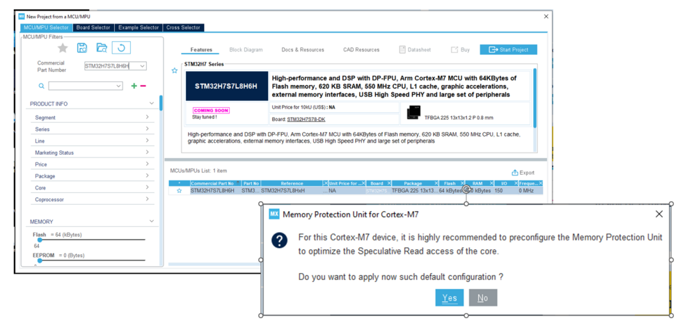
To get started on the project, use the STM32H7S7L8H6H board.
1. Select this board by referring to the Board Selector displayed in the figure below.
2. As project manager, make sure you name the project and verify that all three subprojects are selected.
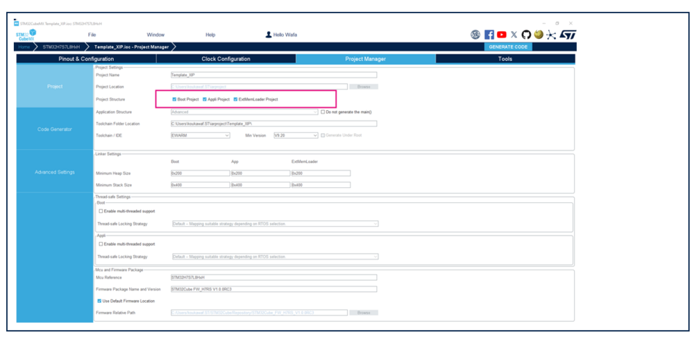
4.1. Boot subproject Configuration
The BootFlash Boot subproject is mainly built using the External Memory Manager middleware and this project is responsible for three operations:
- System initialization.
- Initialization of external memory(ies).
- Application start (XIP (eXecute In Place) or LRUN (Load & Run)).
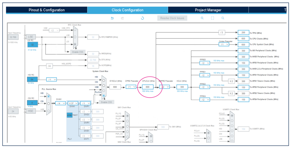
STEP1: Clock configuration.
1.To reach the highest performance, set the clock to max frequency for both Boot and ExtMemLoader subprojects:
Select the system clock at 600 MHz:
- Select HSI from PLL1 Source Mux.
- Select PLLCLK from System Clock Mux.
- Set HCLK to 600 MHz.
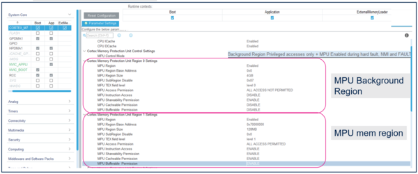
STEP2: Configure the Arm® Cortex®-M7 MPU to define:
- A background region to set default attributes for all regions and prevent speculative accesses on Normal memory type.
- A region of RAM to store non cacheable buffer.
1. Enable ICACHE.
2. Enable DCACHE.
3. Enable MPU.
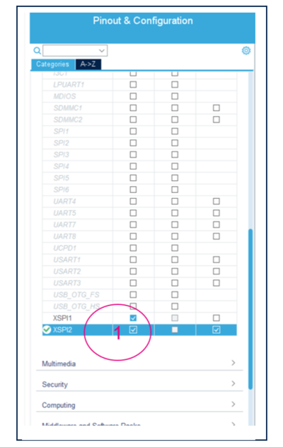
STEP3: To configure the external memory peripheral, select the peripheral connected to the external memory and select the Boot context.
1. In this example, XSPI2 instance corresponds to the interface to the serial NOR SFDP memory on H7RS Discovery board (MB1736-HS7S78-DK).
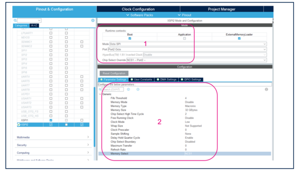
2.The user must configure the XSPI2 depending on the used external memory.
- Select Octo SPI mode.
- Select the Port and the Chip Select.
- Set the parameters of XSPI2 instance as shown below to connect NOR SFDP memory.
3.Set the XSPI2 clock to 200 Mhz and lock it to 200 Mhz.
STEP4: To simplify the use of the External memory manager, select and configure the EXTMEM_MANAGER middleware.
1. Select the EXTMEM_MANAGER middleware.
2. Activate the EXTMEM_MANAGER middleware.
3. Select XSPI interface.
4. Select the driver of NOR SFDP memory.
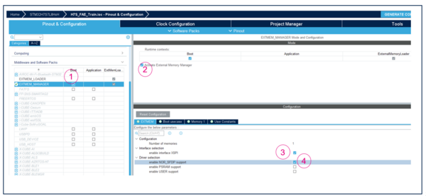
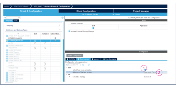
5.Configure the Boot use case to execute In Place (XIP)
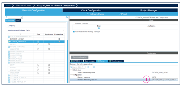
6. Configure the memory data lines interface to 8 lines for octal mode
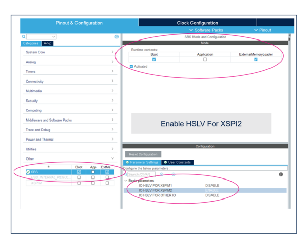
STEP5: Enable IO HSLV.
4.2. ExtMemLoader subproject Configuration
ExtMemLoader is a subproject used to generate a binary library capable of downloading an application to external memory. This binary is called a "Loader" and can be used by the IDE or the STM32CubeProgrammer.
This system initialization function performs the following operations:
- Initialize the system:
- Irq disabling (a loader does not use any irq).
- Enable the cache for performance purpose.
- Initialize the HAL context.
- Disable any ongoing MPU configuration.
- Clock configuration with maximum speed.
- Initialize the memory
- peripheral associated with the memories.
- used the EXTMEM_MANAGER middleware to initialize the memory.
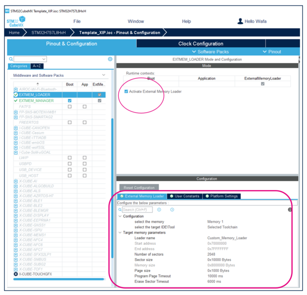
STEP1: Configure the External Memory loader.
1. Select the External Memory loader middleware.
2. Activate the External Memory loader middleware.
4.3. Application subproject Configuration
The Application context (Appli) is the end user application stored in the external memory and its execution is initiated by the Boot context. This process causes the application to inherit from the configurations made by the Boot context.
In this application, we use the PO1, PO5 LEDs to prepare a simple application and load it into the external NOR-SFDP memory.
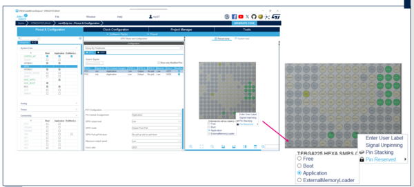
4.1. Compile and flash
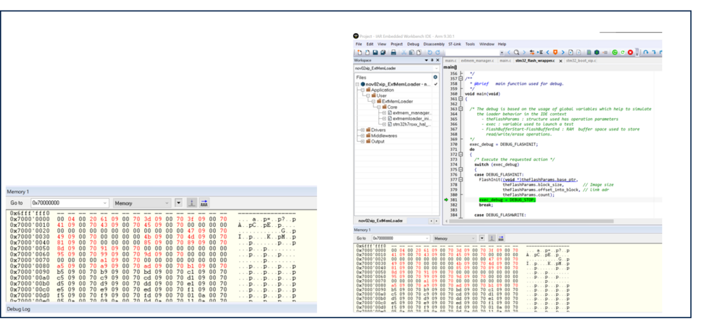
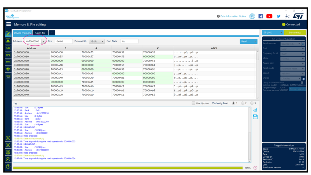
- To view the base address of XSPI2 where the user application is loaded, open the memory view and observe the memory address 0x70000000.
4.2. STM32CubeProgrammer loader file Generation
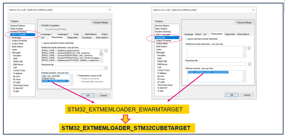
To generate STM32CubeProgrammer loader file from the IAR ExtMemLoader project, you must follow the 4 steps below:
STEP1: Change Defined Symbols C/C++/Assembler preprocessors.
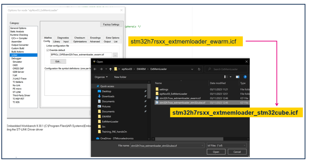
STEP2: Change the linker file
STEP3: Set the generated loader in the STM32CubeProgrammer
There are two methods available to configure the generated loader in the STM32CubeProgrammer:
- A Manual method to configure the generated loader in the STM32CubeProgrammer :
1.Rebuild the ExtMemLoader Project.
2.Rename the *.out project to *.stldr.
3.Copy the *.stldr into binary path of the STM32CubeProgrammer below :
C:\ProgramFiles\STMicroelectronics\STM32Cube\STM32CubeProgrammer\bin\ExternalLoader\
- An automated method to configure the generated loader in the STM32CubeProgrammer
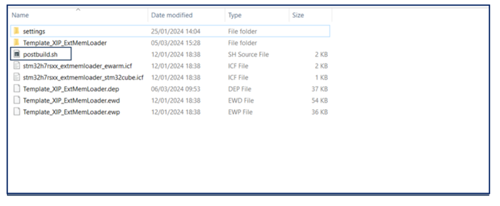
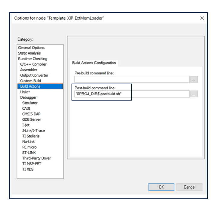
1.The postbuild.sh shell script is responsible for automating all the steps that were previously done manually.
2. Include the postbuild.sh script in your project's build settings.
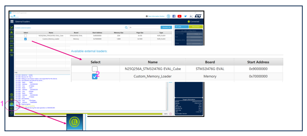
4.Launch the STM32CubeProgrammer.
5.Connect the board.
6.Select the new added loader in the STM32CubeProgrammer.
STEP4: Check Application using the new added loader.
5. STM32CubeMX FlashLess Application Configuration
This section explains how to generate an ExtMemLoader using STM32CubeMX for STM32N6 devices.
STEP1: ExtMemLoader project creation
To get started on the project, use the STM32N657X0H3Q MCU
- Go to STM32CubeMX tool and choose Access to MCU SELECTOR.
- Search for the part number that you use.
- After selecting the adequate part number, please choose the project structure that you need in your project.
STEP2: CONNECTIVITY category
- 1 Go to Pinout & Configuration/Connectivity category.
- 2 Check XSPIM then choose its Mode.
- 3 Check XSPI2 then select the XSPI2 mode, the Port and the Chip select override adequate.
- 4 Write the necessary XSPI2 configuration in the Parameter Settings section.
STEP3:Middleware and Software Packs
- 5 Check FSBL in EXTMEM_MANAGER section.
- 6 Pick Activate External Memory Manager.
- 7 In Boot usecase configuration, select boot code generation.
- 8 In Memory 1 configuration, change the number of memory data line to EXTMEM_LINK_CONFIG_8LINES.
- 9 Check ExtMemLoader in EXTMEM_LOADER section
- 10 Pick Activate External Memory Loader
- 11 Go to External Memory Loader section and enter the necessary configuration:
- Target IDE/Tool
- Loader name
- Number of sectors
- Sector size
- 12 Activate system supply configuration protection in the PWR features table.
- 13 Check I/O voltage range selection.
- 14 Set VDDIO2 and VDDIO3 voltage range selection to 1.8 V in parameters settings.
STEP5:Clock Configuration for ExtMemLoader
- 1 Choose the HSI as an input clock source for the PLL1.
- 2 Configure the PLL1 input frequency and the multiplication and division factors by setting DIVM1 of PLL1 /4 and DIVN1 X75.
- 3 Configure the PLL1 output frequency to achieve 75 MHz (/16).
- 4 Configure IC3 as the source for the XSPI2 Mux.
- 5 Set the XSPI2 clock frequency to 75 MHz.

STEP6:ExtMemLoader project Manager
- 1 Configure the project by setting the name, choosing the location, enabling the ExtMemLoader and FSBL options, and specifying the path to the toolchain folder.
- 2 Select the toolchain/IDE, then generate and open the generated project.
- 1 Uncheck the "Download extra image" option in the settings under Debugger/Images.
- 2 Set the reset type to "System" in the settings under STLink/Setup.

STEP7:Compile and flash
•To confirm that the application is correctly positioned in the memory space allocated for XSPI2:
- 1 Open the Memory View in your development environment.
- 2 Observe the address to verify the location where the user application is loaded.
5.1. IDE switch STM32Cube/IDE Loader
From the EWARM ExtMemLoader project, you can generate the STM32CubeProgrammer loader file. To switch between the EWARM Loader and STM32Cube Loader within the IDE/tool, manually perform the following configurations:
EWARM Loader Configuration
- Set Target: Configure STM32_EXTMEMLOADER_EWARMTARGET and remove STM32_EXTMEMLOADER_STM32CUBETARGET.
- Linker File: Use stm32n6xx_extmemloader_ewarm.icf.
STM32Cube Loader Configuration
- Set Target: Configure STM32_EXTMEMLOADER_STM32CUBETARGET and remove STM32_EXTMEMLOADER_EWARMTARGET.
- Linker File: Use stm32n6xx_extmemloader_stm32cube.icf.
5.1. References


