Target description
The purpose of this article is to provide step-by-step instructions on how to configure a boot path.
The example below demonstrates how to configure and provision a boot path for an STiRoT (ST immutable root of trust) and generate an application code using CubeMx.
The initially generated code is modified to blink the green led embedded on the board.
Read Secure Boot STM32H7RS How to Introduction before starting the practical example described below.
For more technical details that may be useful to know before getting started, check out the following articles:
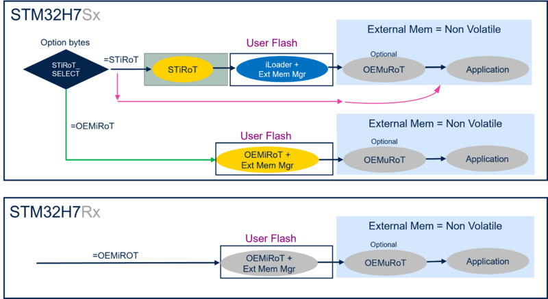
The figure below shows the possible boot paths for the STM32H7RS.
The STiRoT is only supported for the STM32H7S, since it requires the CRYP hardware accelerator not supported on the STM32H7R.
The example described in this article uses the boot path indicated in the figure bellow.
Prerequisites
To execute the example described below, you need an STM32H7S-DK discovery board:
You will also need the following tools:
- STM32CubeMX_6.11.0 or later
- STM32CubeProgrammer_rev2.16.0 or more recent (with trusted package creator (TPC) selected at installation).
- IAR Embedded Workbench® rev 9.60 or later.
- or IAR Embedded Workbench® rev 9.20.1 or later + IAR Patch EWARMv9_STM32H7R-Sxx_Vx.x.x
- IAR patch is available in the STM32CubeFW: STM32Cube_FW_H7RS_Vx.x.x\Utilities\PC_Software
Note:
- STM32 Trusted Package Creator (TPC) is automatically installed during the STM32CubeMX installation. This TPC version is dedicated to STM32CubeMX and installed in the STM32CubeMX/utilities folder.
- The latest STM32Cube_FW revision is installed through STM32CubeMX.
1. Setting up the STM32CubeMX project
Launch STM32CubeMX
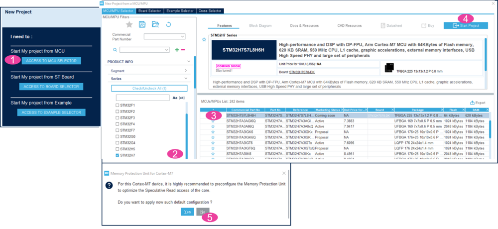
- Click on access to MCU selector (for this example, it is easier to enable only the necessary single GPIO, so it is advised to use the MCU selector instead of the board selector).
- From the series column, select STM32H7.
- Select STM32H7S7L8H6H, commercial part number of the device used in STM32H7S78-DK.
- Click start project.
- For the memory protection unit, select no.
Create the STM32CubeMX project:
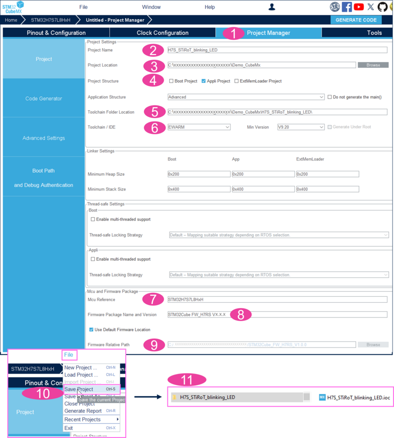
- Select the project manager tab.
- Type the name of the project.
- Choose a folder for the project (avoid a long path). If it does not already exist, the related folder is created.
- Tick appli project.
- Select the relevant toolchain; for this example, EWARM is used.
- The correct MCU reference must be already filled in.
- The firmware package name and version must be correct if the latest STM32CubeFW has been installed (see prerequisites).
- The firmware relative path must indicate the path to your STM32CubeRepository.
- Select file > save project.
- The project folder (if it does not already exist) and the H7S_STiRoT_blinking_LED.ioc file are created.
2. GPIO configuration
For the proposed example, a single GPIO is defined to blink the green LED available in the discovery kit.
- PO1 is controlling the green LED (see MB1736 schematic).
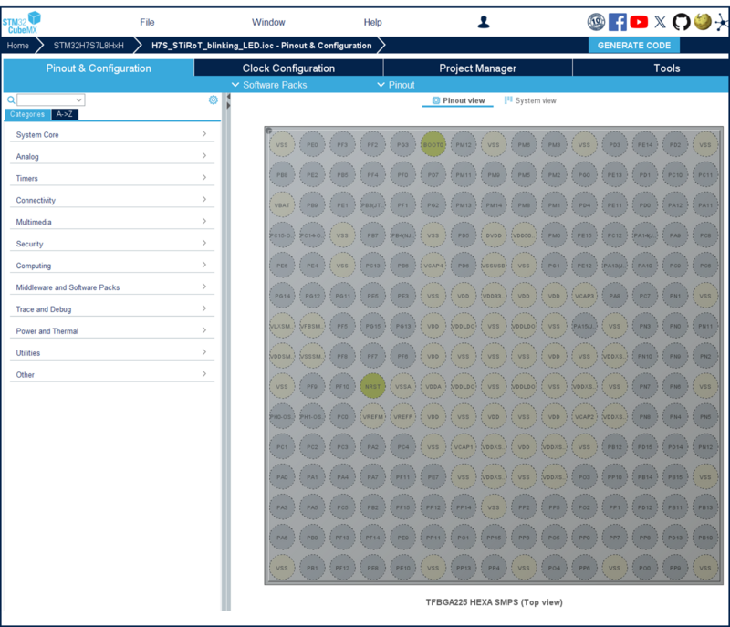
- In STM32CubeMX, select the pinout & configuration window.
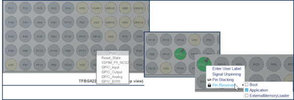
- Click on PO1 and select GPIO_Output. This configures a push pull output that is needed to drive an LED.
- Right click on PO1 -> pin reserved -> application. This pin is now assigned to the application code that will be generated later.
- Click on system core and select GPIO. A summary of the newly configured setting is displayed as shown in the figure below:
3. STiRoT boot path and debug authentication configurations
To configure the boot path indicated in figure 1, proceed as follows:
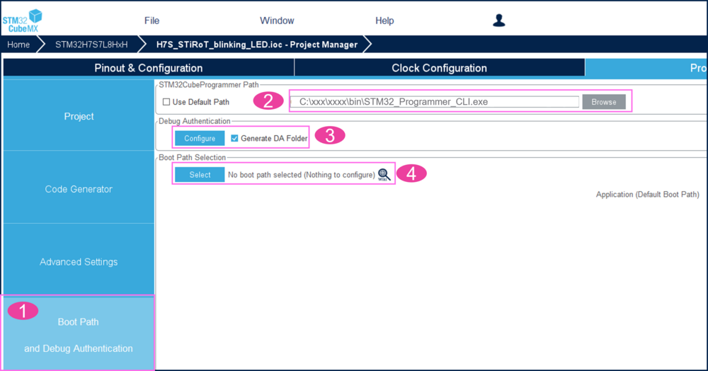
- Click on boot path and debug authentication.
- In case the STM32CubeProgrammer is not installed at the default installation path. Click browse, select the path and STM32_Programmer_CLI.exe.
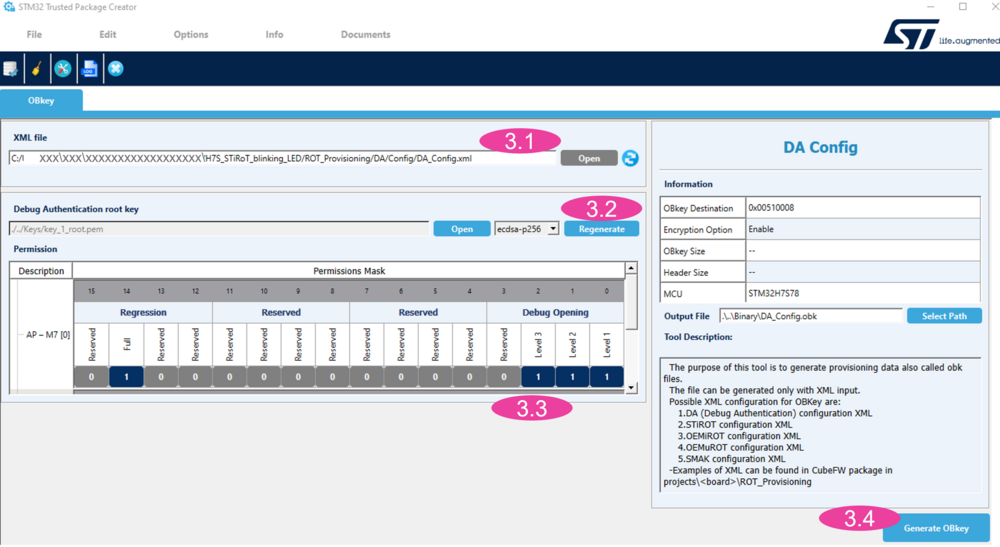
- Tick generate DA folder, select configure, the debug authentication window opens (see figure below).
- The path to the debug authentication xml file is indicated.
- A new DA root key can be generated. If a new key is generated, do not lose it since it is required for debug opening and regression (for trials, it is advised to keep the default key).
- The permission mask can be modified by clicking on the dark blue fields. By default, the debug opening for all HDP isolation levels is allowed and the full regression. For this step by step, just keep all the fields selected.
- Click generate OBkey.
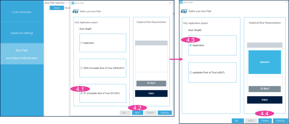
4. Click select in the boot path selection.
- 4.1 Tick ST immutable root of trust, to select an STiRoT boot path.
- 4.2 Click next.
- 4.3 Tick application, according to figure 1, this example is without an OEMuRoT.
- 4.4 Click finish.
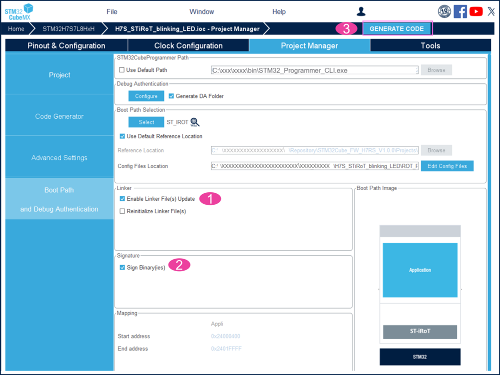
- To generate the initial code, follow the steps of the figure below:
- Tick enable linker file update.
- Tick sign binary (the signed and encrypted binary will be automatically generated during the compilation through the IDE (post build).
- Click generate code.
- Click on open project.
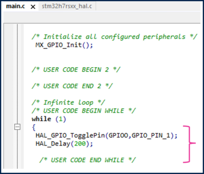
- In the main.c, add the following code to toggle the PO1 pin for the green LED.
  HAL_GPIO_TogglePin(GPIOO,GPIO_PIN_1);
  HAL_Delay(200);
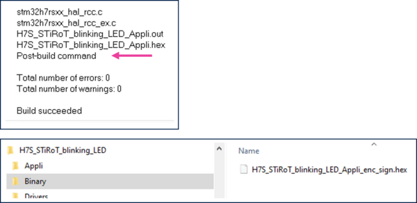
- Compile the code using the IDE (project > rebuild all).
- Note that at the end of the compilation a post build command is launched. It generates the encrypted and signed user application code image (see figure below).
4. Device provisioning
4.1. Device provisioning introduction
During the provisioning step (for more details see STiRoT STM32H7S How to Intro article):
- The option bytes are configured. It includes the provisioning of the debug authentication.
- The encrypted and signed binary file is uploaded to the external flash memory (encrypted in AES with STiRoT key).
- The image in the download slot is decrypted and stored reencrypted in the external flash memory installation slot (encrypted in AES with MCE key).
- The device is set in closed state.
- A provisioning script guides the user during the provisioning steps.
- Note:
- All the data transfers between internal RAM and external flash are managed by the provided iLoader code. This firmware is the first installed in clear in the flash embedded in the device.
- Important reminder: Before the device is set in closed state, the debug authentication must have been provisioned. Using the provided script, all the needed steps are ensured in the right order and executed automatically.
4.2. Env.bat file update
The figure below shows where the env.bat file is located in the generated project environment.
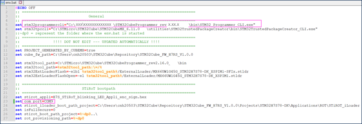
- Edit this file with a text editor, as shown in the figure below.
- Do not modify the path to the STM32 trusted package creator included in STM32CubeMX!
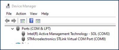
- The correct COM_port needs also to be updated. The COM port can, for instance, be found out using the windows device manager (COM9 for the example of figure below).
4.3. Board provisioning, firmware installation and product state setting
The board provisioning is performed using the provided script.
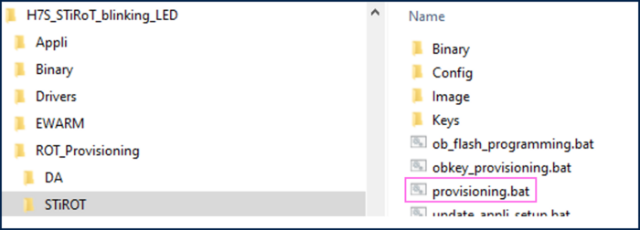
This script is available in the project structure created previously using STM32CubeMX.
All the steps to be followed are indicated by the script.
- Connect your board using the USB cable (USB STLINK connector).
- Double-click on the provisioning.bat file shown in the figure above.
Step 0:
- The final product state is chosen (do not choose LOCKED since this is a definitive product state that disables the debugger and cannot be changed anymore).
- The debug authentication method is chosen. For this tutorial, choose CERTIFICATE.
- Once the device is in CLOSED state, the password method allows to perform a full regression, using the defined password.
- Once the device is in CLOSED state, the certificate method allows using a key to perform the operations allowed by the certificate (see in the next sections).
- The next step is to compile the iLoader.
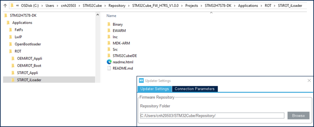
- The iLoader firmware is available in the repository location defined in the updater settings path of STM32CubeMX: help -> updater settings.
This firmware is managing all the transfers between and from the external OCTOSPI flash memory.
- The iLoader firmware is available in the repository location defined in the updater settings path of STM32CubeMX: help -> updater settings.
- Open the iLoader project at the repository location and rebuild all files using the IDE (for this tutorial EWARM).
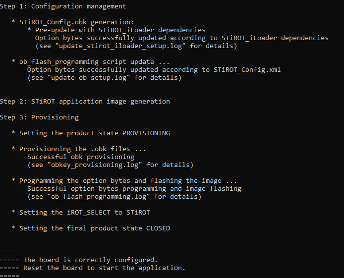
Step 1:
- This step is automatically performed by the script configuring the needed option bytes.
Step2
- The application image is automatically generated.
Step3
- The board provisioning and the image flashing is performed by the script.
- The CLOSED state defined at the beginning of the script is set.
- Close the script window.
4.4. Installed firmware execution
- Reset the board, the green LED is blinking.
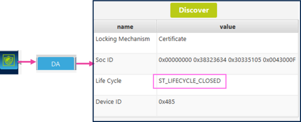
- Start STM32CubeProgrammer, click on the shield -> DA -> discover.
The product state CLOSED is indicated. - Trial to connect the STM32CubeProgrammer will generate an error since in CLOSED state the debugger is deactivated.
4.5. Regression
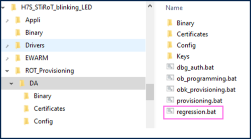
- The generated DA folder includes a regression script, as shown in the figure below.
- The execution of this script is removing all the configuration and installed firmware.
- Double-click on regression.bat.
The certificate and key located in the folders shown in the figure above are used by the script. - For this how to start the debug authentication using a CERTIFICATE has been used. It needs to be entered at the beginning of the regression script execution.
- A success message is displayed.
- The STM32CubeProgrammer can be connect and shows that the settings and firmware are removed.
