SMAK for STM32H5

1 Introduction

The Secure Manager Access Kit (SMAK) provides an environment where users can:

  • Develop nonsecure applications that use the Secure Manager services.
  • Prepare the final encrypted images used for OEM secure manufacturing.

The SMAK details are described in the next chapters.

2 Architecture

2.1 Ecosytem architecture

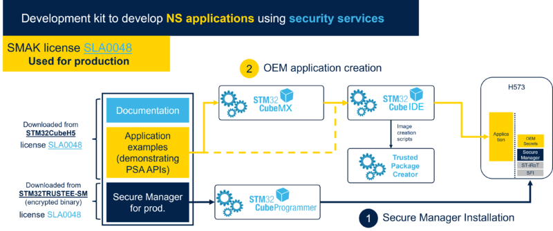
The SMAK ecosystem is composed of:

  • The Secure Manager binary, available as an encrypted image from STM32TRUSTEE-SM[1].
    • The image is delivered with the software license agreement SLA0048[2].
    • It can be used for production purposes.
  • The STM32Cube embedded firmware package available from STM32CubeH5 [3], containing:
    • Scripts to configure and install Secure Manager, relying on STM32TrustedPackageCreator and STM32CubeProgrammer tools.
    • Template and example projects (for STM32CubeIDE [4], KEIL[5] and IAR[6]) to develop nonsecure application using Secure Manager services. They contain pre-integrated prebuild and postbuild scripts relying on STM32TrustedPackageCreator to generate a signed and encrypted image, and download scripts relying on STM32CubeProgrammer to flash nonsecure application image.
  • STM32TrustedPackageCreator and STM32CubeProgrammer[7], for above needs.
  • STM32CubeMX[8], to generate nonsecure application projects for Secure Manager.
  • IDEs (STM32CubeIDE[4], IAR[6] or KEIL[5])


The following diagram presents the SMAK ecosystem architecture.
Security SMAK.png

2.2 Software architecture

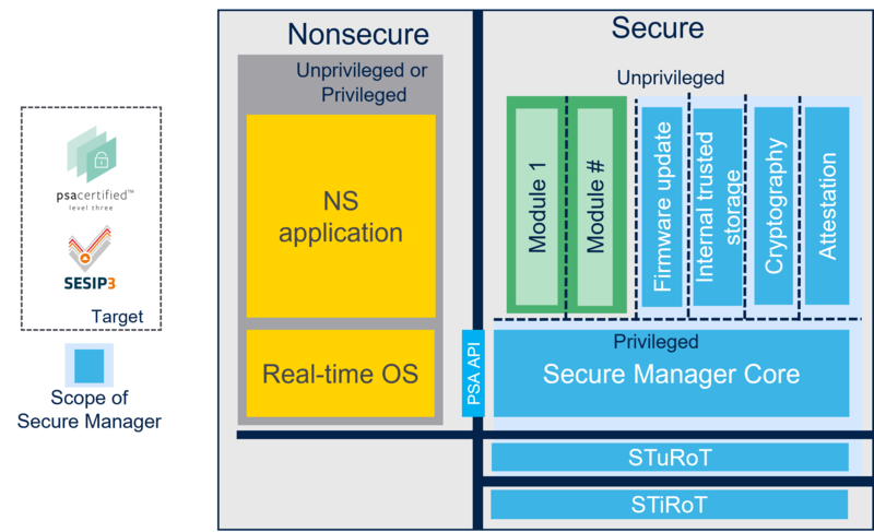
Secure Manager is executed in a secure processing environment (SPE).
It is composed of STiRoT and STuRoT, in addition to the Secure Manager.
It is responsible for Secure Boot and Secure Firmware Update, and it provides secure services to nonsecure (NS) applications at runtime.

Secure Manager is composed of:

  • A 2-level Root of Trust
    • An immutable Root of Trust (STiRoT)
    • An updatable Root of Trust (STuRoT)
  • The Secure Manager Core
  • Secure Services such as
    • Cryptography
    • Initial attestation
    • Trusted storage
    • Firmware update

Additionally, trusted applications, also called Secure Modules, can be added by the user, but are not part of the Secure Manager.

The following figure describes the Secure Manager software architecture.


Security Secure Manager.png

Info white.png Information
The secure modules are not part of the Secure Manager.

For more information about the Secure Manager components (STuRoT, Secure Manager Core...), refer to Secure Manager components.

3 Security model

3.1 Stakeholders

The stakeholders involved in the security model are:

  • STMicroelectronics, who owns the Secure Manager.
  • The OEM who owns the nonsecure application and possibly Secure Modules, and is responsible for the system integration.
  • Optionally, third-party Secure Module owners who own Secure Modules.

3.2 Asset confidentiality

The Secure Manager ensures stakeholders asset confidentiality by protecting:

  • Secure Manager assets against the Secure Modules and nonsecure application.
  • Secure Module assets against the nonsecure application and other Secure Modules.
  • Nonsecure application assets against Secure Modules using the internal trusted storage (ITS) service.

3.3 Multi-tenant IP protection

The Secure Manager supports multi-tenant IP protection, meaning that each Secure Module (from the OEM or third-party) is isolated from the others by using sandboxes.

3.4 PSA level 3 isolation

The security model is based on PSA level 3 isolation, ensuring that the secure domain is isolated from nonsecure domain. This means that the Secure Manager and Secure Modules are protected from access by any nonsecure applications (hardware and software).
This isolation also ensures that privileged secure domain is separated from unprivileged secure domain, meaning that the Secure Manager Core is protected from access by secure services and Secure Modules.
Additionally, it ensures that the secure partitions are fully isolated. This means that each secure partition (secure services and Secure Modules) is sandboxed and can only access its own resources. This protects each secure partition from access by other secure partitions, and it provides protection for the Secure Manager Core.

3.5 Type of assets

The following table describes which types of assets are protected.

Code asset Volatile data asset Nonvolatile data asset ITS data Peripherals
Secure Manager Yes Yes Yes Yes Yes
Secure Module Yes Yes Yes Yes Yes
Nonsecure application Yes Yes Yes Yes Partially (see note below)
Info white.png Information
Nonsecure application peripherals are accessible by a Secure Module if this peripheral is described in the Secure Module header. This means that the OEM must review the Secure Module header with the third-party module owner to ensure that this module cannot access any nonsecure application peripheral assets.

4 Feature overview and secure services

The Secure Manager is responsible for supplying secure services at boot-time and runtime.

The boot-time services are available after a power-on or system reset and are responsible of secure boot and secure firmware update.

The runtime secure services can be used by nonsecure applications running on nonsecure domain, as well as other secure modules running on secure domain. These services are defined by the PSA standard.

The following services are supported:

  • PSA cryptography: supplies cryptographic services, such as authentication or encryption, based on hardware cryptographic acceleration with side-channel resistance.
  • PSA internal trusted storage (ITS): supplies services for storing the most important assets (such as keys and data) in the internal flash memory, ensuring integrity, and confidentiality. Be aware that ITS file system is encrypted.
  • PSA attestation: supplies services to authenticate a device. To do this, a unique signed token is generated for each device, which can be later authenticated by a server.
  • PSA firmware update: supplies services to download new firmware images and perform image updates.

The Secure Manager also supports firmware installations and updates, based on direct image download in the download slot (this feature must be enabled using OEM Secure Manager configuration parameter) instead of PSA firmware update API.

4.1 PSA services

4.1.1 PSA cryptography service

4.1.1.1 Description

This service provides an implementation of the PSA cryptography API as defined in the Arm PSA Cryptography API document[9].
Cryptographic algorithms implementation relies on cryptographic hardware accelerator peripherals of the device (PKA, SAES, HASH, TRNG) whenever possible. The table below lists the supported functionalities, as well as the protections they implement.

4.1.1.2 Services

The main services are:

  • Library management
    • Library (PSA cryptography service) initialization
  • Key management
    • Opaque key identifiers
    • Key lifetimes (volatile, persistent)
    • Key policy
    • Key import, generation, derivation, and copy
  • Symmetric cryptography
    • Message digests (Hash)
    • Message authentication codes (MAC)
    • Encryption and decryption
    • Authenticated encryption (AEAD)
    • Key derivation
  • Asymmetric cryptography
    • Asymmetric encryption
    • Hash and sign
    • Key agreement
  • Randomness

The following table describes the implemented operations, algorithms, and key lengths.

Operations Algorithms Key lengths Modes Implementation SCA/DPA resistant Fault resistant
Get entropy TRNG N/A N/A Hardware N/A N/A
Encryption, decryption AES 128, 256 ECB, CBC, CTR, CFB Hardware YES YES
Authenticated encryption, decryption AES 128, 256 GCM, CCM Hardware YES YES
Cipher-based message authentication code AES 128 CMAC Hardware YES YES
Cryptographic hash SHA-11 N/A Digest 160-bit Hardware N/A N/A
Cryptographic hash SHA-2 N/A SHA-224, SHA-256, SHA-384, SHA-512 Hardware N/A N/A
Keyed hashing for message authentication HMAC-SHA2-224 Short, long (>64 bytes) N/A Hardware N/A YES
Keyed hashing for message authentication HMAC-SHA2-256 Short, long (>64 bytes) N/A Hardware N/A YES
Keyed hashing for message authentication HMAC-SHA2-384 Short, long (>64 bytes) N/A Hardware N/A YES
Keyed hashing for message authentication HMAC-SHA2-512 Short, long (>64 bytes) N/A Hardware N/A YES
Asymmetric encryption RSA 2048, 3072 RSAES-OAEP, RSASSA-PKCS1-V1_5 Hardware YES YES
Signature with hashing signature verification RSA 2048, 3072 RSASSA-PKCS1-v1_5, RSASSA-PSS Hardware YES YES
Signature with hashing signature verification ECDSA Up to 521 List of supported hardware ECC curves below2 Hardware YES YES
Key agreement ECDH Up to 521 List of supported ECC curves below2 Hardware YES YES
Encryption, decryption DES1 128, 256 ECB, CBC Software NO NO
Encryption, decryption Triple DES 128, 256 ECB, CBC Software NO NO
Key derivation HMAC-based N/A N/A Hardware YES YES
  1. Weak - not recommended.
  2. The following elliptic curves are supported: secp224r1, secp256r1, secp384r1, secp521r1, secp256k1, bp256r1, bp384r1, and bp512r1. secp192r1 and secp192k1 are also supported, but not recommended.

Note:
All implementations that manipulate private keys are protected against side-channel and timing attacks.

4.1.1.3 Pre-provisioned DUA user key

To ease OEM manufacturing, STMicroelectronics has pre-provisioned STM32 devices with a unique asymmetric key pair for user purpose. This ECC key pair is accessible through the PSA crypto API using a specific key ID.

The following services are available:

  • Sign with the DUA user private key.
  • Export the DUA user public key.

4.1.2 PSA initial attestation service

4.1.2.1 Description

This service provides an implementation of the PSA initial attestation API, described in the PSA Attestation API document[10].

The service allows the application to prove the device identity during an authentication process to a verification entity. The initial attestation service can create a entity attestation token (EAT) on request, which contains a fix set of device specific data. The EAT is encoded according to the CBOR format and signed according to COSE standard.
To ease OEM manufacturing, STMicroelectronics has pre-provisioned for each device an ECC asymmetric unique key pair and a certificate used for device unique authentication. It is called DUA initial attestation key. It is dedicated and used by the PSA initial attestation service to sign the token. The table below lists the fields contained in the EAT.

Claim Mandatory Description Value Implemented
Auth challenge Yes Authenticated challenge is an input object of the caller (user who request the token). 32, 48 or 64 bytes length. Value is provided by the caller. Yes
Instance ID Yes Unique identifier of the device instance. Concatenation of 0x1 and the hash of the public key used for initial attestation (DUA initial attestation key). Yes
Verification service indicator No A hint used by a relying party to locate a validation service for the token N.A. No
Profile definition No Name of a document that describes the profile of the report N.A. No
Implementation ID Yes Unique identifier of the underlying immutable PSA RoT. ST immutable firmware (ROM) version (32 bytes in STM32 system flash at address 0x0BF96000). Yes
Client ID Yes Partition ID of the caller (application who requested the token). Signed 32-bits. -1 for NSPE firmwares. Application Service Identifier (ASID) of the secure service or secure module for SPE firmwares. Yes
Security life cycle Yes Current life cycle state of the PSA RoT. Product state Closed (SL_SECURED) or TZ-Closed (SL_NON_PSA_ROT_DEBUG). Yes
Hardware version No Metadata linking the token to the GDSII that went to fabrication for this instance. String encoded from the DBGMCU IDCODE register. Yes
Boot seed Yes Random value created at system boot time. Random number. Yes
Software components Yes A list of software components that represent all software managed by the PSA RoT See table below. Yes

The table below lists the fields contained in each Software component.

Software component fields Mandatory Description Value Implemented
Measurement type No A short string representing the role of this software component. String. "BL" for STuRoT, "SPE" for Secure Manager, "ARoT" for a Secure Module, "NSPE" for nonsecure application Yes
Measurement value Yes The hash of the invariant software component in memory at startup time. 32 bytes. SHA256 of the software component. Yes
Version No The issued software version in the form of a text string. String encoded in CBOR. For example "1.0.0" Yes
Signer ID No The hash of a signing authority public key for the software component. 32 bytes. SHA256 of this public key. Yes
Measurement description No Represents the way in which the measurement value of the software component is computed. ASCII string. "SHA256" Yes

The following figure displays an example of a decoded token, using the iat-verifier tool from the trustedfirmware middleware in the STM32CubeFw. This token was generated with the configuration:

  • Authenticated challenge from the user (caller): null value of 32 bytes.
  • Token get from the nonsecure application (caller): negative Client ID value ('-1').
  • Product State: TZ-Closed ('SL_NON_PSA_ROT_DEBUG').
  • Components installed: STuRoT ('BL'), Secure Manager ('SPE'), nonsecure application ('NSPE') and an OEM module ('ARoT').
Example of decoded token with an OEM module installed
4.1.2.2 Services

The main services are:

  • Get token size (useful to allocate the right buffer size to get the token).
  • Get token.

4.1.3 PSA internal trusted storage service

4.1.3.1 Description

This service provides an implementation of the PSA internal trusted storage (ITS) API defined in the Arm© PSA Secure Storage API document [11].

It allows the writing of data in the microcontroller built-in flash memory region that is isolated from the nonsecure application and from other secure services by hardware security protection mechanisms. It provides a nonhierarchical storage model (like a file system), where a linearly-indexed list of metadata manages all the assets. The data are generally small pieces of data (such as private key, credentials).

ITS includes the following functionalities:

  • Confidentiality: data are located in a secure area, protected from unauthorized access by hardware isolation (TZ, MPU) of the flash memory access domain. Data are encrypted using a symmetric algorithm and a unique STMicroelectronics 256-bit key.
  • Access control: a specific mechanism establishes the identity of the requester (a nonsecure entity, a secure entity, or a remote server).
  • Integrity: the internal flash memory device provides resistance to hardware physical access attacks.
  • Reliability: ITS provides resistance to power failure scenarios and incomplete write cycles.
  • Configurability: ITS size can be configured by the OEM based on Secure Manager memory configuration selection. Additional ITS size are considered in ST roadmap.
4.1.3.2 Services

The main ITS services are:

  • Set data in the ITS area (data are identified by a unique identifier (UID)).
  • Get data from the ITS area.
  • Remove data from the ITS area.
  • Get data information (metadata).

Manipulated objects (data) can be data or keys. The metadata contain the data size and some attributes that define how they can be accessed (immutable, public...).
Each data is associated with a owner ID. The nonsecure application owner ID is 0xFFFFFFFF. The Secure Service (respectively Secure Module) owner ID is the ASID of the Secure Service (respectively Secure Module). The ASID is encoded with 32 bits.
A data can be accessed only by the data owner (Owner ID) unless the data is declared as public.
When data are provisioned using ITS builder tool, the supported key format is limited (for details, see ITS builder documentation in STM32CubeH5 [3] at ./Utilities/PC_Software/ITSbuilder/README.md).

4.1.3.3 ITS provisioning

The ITS can be provisioned in two ways:

  • The first way is to use the PSA internal trusted storage API to provision data and keys in the ITS. In this case, it is the nonsecure application that performs the provisioning at runtime (generally during the OEM manufacturing phase).
  • The second way is to use Factory Internal Trusted Storage provisioning. The OEM prepares the data and keys to provision, using the STMicroelectronics ITS builder tool (on a PC). This tool generates an encrypted and authenticated blob (using OEM keys used for nonsecure application preparation) containing the data and keys. The OEM can later install this blob in a secure way during production. The encrypted blob is programmed during production but blob installation and initialization in ITS filesystem is done at the first product power on.

For more information on ITS builder, refer to ITS builder documentation in STM32CubeH5 [3] at ./Utilities/PC_Software/ITSbuilder/README.md.

Notes:

  • In the current Secure Manager memory configurations, the blob size is limited to 8 KB.
  • The maximum data and key size is 2016 bytes.
  • The installed data and keys can only be used by the nonsecure application, using the PSA internal trusted storage API.

4.1.4 PSA firmware update service

4.1.4.1 Description

This service provides an implementation of the PSA firmware update API defined in the PSA Firmware Update API document [12]. It provides a standard and platform agnostic interface for firmware updates.
The firmware update scheme is based on a dual slot: one active slot and one download slot. The active slot is used to execute the firmware and the download slot used to download the new image to be installed.

The following images can be updated:

  • Nonsecure application
  • STuRoT
  • Secure Manager
  • Secure Modules (each independently)

The installation flow is as follows:

  • The nonsecure application (update agent) gets information about the installed images (name, installation status, version, etc.).
  • It downloads the image to the secure download slot.
  • It requests image installation.
  • It resets the device to execute the secure boot stages (STiRoT and STuRoT) that performs the installation in the active slot and jumps to the nonsecure application.
  • The nonsecure application must accept the image using its specific acceptation criteria (nonsecure application dependent).
    • If the acceptation criteria is met, the nonsecure application informs the firmware update service that the image is accepted.
    • If the acceptation criteria is not met, the nonsecure application generates a reboot. The secure boot stages are executed, set the image to rejected state, and performs a rollback to the previous valid image which was swapped in the download slot.

During the installation, the image in active and download slots changes states. The possible states are:

State Value Description
UNDEFINED 0x0 Empty download slot. Or download slot containing a former image whereas new image on the active slot has been successfully installed.
CANDIDATE 0x1 Image candidate present in the download slot.
INSTALLED 0x2 Image accepted by the nonsecure application (update agent) in the active slot.
REJECTED 0x3 Image not accepted by the nonsecure application (update agent), swapped back to download slot.
PENDING_INSTALL 0x4 Image candidate in the active slot, waiting for image acceptance from the nonsecure application (update agent).
REBOOT_NEEDED 0x5 Reboot is needed to finalize the image candidate swap from download slot to active slot.

The image installation (swap) is resistant to asynchronous power down and system reset. Nevertheless, if a power down occurs whereas the new image has not been completely written to the download slot, the image installation process must be restarted.

4.1.4.2 Services

The services are:

  • Get image information (state, version, digest) for an image ID.
  • Write image to the download slot (staging area) (image state "CANDIDATE").
  • Request the installation of the downloaded image and inform the client that a reboot is required to execute the secure boot stages (image state "REBOOT_NEEDED").
  • Reboot the device to execute secure boot stages:
    • If there is an image to install in the download slot, the secure boot stage installs the image (image state "PENDING_INSTALL") during the boot. If the image to install is not valid image, the image is not installed and is erased from the staging area (image state "UNDEFINED").
  • Accept the image. The image is fully installed and becomes the new valid image (image state "INSTALLED").

An image ID is composed of a slot ID and a type ID.
The slot ID indicates if the image is located in the download or active slot.
The type ID indicates the type of image as described in below table.

Type ID Description
NONSECURE nonsecure application
BL STuRoT
SECURE Secure Manager
MODULE0 Secure Module 0

4.2 Other services

4.2.1 Power-on and system reset

After each product power-on or reset, the platform starts to execute the Secure Manager root of trust (STiRoT, STuRoT, and Secure Manager) that manages the secure initialization of the platform. If a candidate STuRoT image is present in the STuRoT download slot, STiRoT performs the installation in the STuRoT active slot. If a candidate Secure Manager, nonsecure application, or Secure Module image is present in the respective download slot, STuRoT performs the installation in the respective active slot.

4.2.2 Firmware update with direct writing to download slot

The OEM can configure the Secure Manager in a way that it jumps to the system bootloader when there is no valid image in at least one of the active slot (nonsecure application, STuRoT, Secure Manager, or Secure Module). In this case, the OEM can use the system bootloader to download an encrypted image in the download slot. After a reset, the Secure Manager detects the downloaded image and performs the installation if the image is valid.
This service can be used to update STuRoT, Secure Manager, the nonsecure application, or a Secure Module.

4.2.3 Certificate utility

Two STMicroelectronics certificates are provisioned in the STMicroelectronics device system flash memory. They are both used for the device unique authentication (DUA). The DUA initial attestation certificate is used for Initial Attestation purposes, for example the authentication with a cloud. The DUA user certificate is used for user purpose, for example to create a secure communication (TLS).

The certificate utility supplies the following services:

  • Get DUA certificate size based on certificate ID.
  • Get DUA certificate (X509 format) based on certificate ID.

The X509 certificate can be visualized with openssl from a terminal. For X509 certificate details, refer to rfc2459.

The table below lists the fields contained in the X509 certificate (DUA initial attestation or DUA user certificates).

Claim Description
Version Version of X509 format supported.
Serial Number Unique number that identify each certificate and is issued by a certificate authority (CA).
Signature Algorithm The value and algorithm of the certificate signature delivered by the certificate authority (CA).
Issuer Identifies the certification authority that issued the certificate.
Validity Validity period of the certificate with a start and end date.
Subject Identify the entity associated to the certificate.
Public Key Contains the public key of the entity associated to the certificate.
Subject Public Key info Information about the public key (size, curve, algorithm)
Extension Provides additional information about the certificate such as access permissions or usage restrictions.

The figure below presents an example of DUA initial attestation certificate visualized with openssl.

Certificate DUA Initial Attestation.png


The figure below presents an example of DUA User certificate visualized with openssl.

Certificate DUA User.png


5 Interfaces

This chapter describes the interfaces supplied by the Secure Manager to develop a nonsecure application.
The details of the interfaces are described in the header files of the Secure Manager API middleware (./Middlewares/ST/secure_manager_api/) and in the Secure Manager API documentation (./Middlewares/ST/secure_manager_api/SecureManagerAPI.chm).

5.1 PSA interfaces

5.1.1 PSA cryptography service

5.1.1.1 Overview

The PSA cryptography service interface is described in the Arm PSA Cryptography API document[9].
To use this interface, the application must include the psa/crypto.h header file.

5.1.1.2 Function list
Function Description Comment
psa_aead_decrypt() Process an authenticated decryption operation.
psa_aead_encrypt() Process an authenticated encryption operation.
psa_aead_operation_init() Return an initial value for an AEAD operation object.
psa_asymmetric_decrypt() Decrypt a short message with a private key.
psa_asymmetric_encrypt() Encrypt a short message with a public key.
psa_cypher_abort() Abort a cipher operation().
psa_cipher_decrypt() Decrypt a message using a symmetric cipher.
psa_cipher_decrypt_setup() Set the key for a multipart symmetric decryption operation.
psa_cipher_encrypt() Encrypt a message using a symmetric cipher.
psa_cipher_encrypt_setup() Set the key for a multipart symmetric encryption operation.
psa_cipher_finish() Set the key for a multipart symmetric decryption operation.
psa_cipher_generate_iv() Generate an initialization vector (IV) for a symmetric encryption operation.
psa_cipher_operation_init() Return an initial value for a cipher operation object.
psa_cipher_set_iv() Set the initialization vector (IV) for a symmetric encryption or decryption operation.
psa_cipher_update() Encrypt or decrypt a message fragment in an active cipher operation.
psa_close_key() Close a key handle.
psa_copy_key() Make a copy of a key.
psa_crypto_init() Library initialization.
psa_destroy_key() Destroy a key.
psa_export_key() Export a key in binary format.
psa_export_public_key() Export a public key or the public part of a key pair in binary format.
psa_generate_key() Generate a key or key pair.
psa_generate_random() Generate random bytes.
psa_get_key_algorithm() Retrieve the permitted algorithm policy from key attributes.
psa_get_key_attributes() Retrieve the attributes of a key.
psa_get_key_bits() Retrieve the key size from key attributes.
psa_get_key_id() Retrieve the key identifier from key attributes.
psa_get_key_lifetime() Retrieve the lifetime from key attributes.
psa_get_key_type() Retrieve the key type from key attributes.
psa_get_key_usage_flags() Retrieve the usage flags from key attributes.
psa_hash_abort() Abort a hash operation.
psa_hash_clone() Clone a hash operation.
pa_hash_compare() Calculate the hash (digest) of a message and compare it with a reference value.
psa_hash_compute() Calculate the hash (digest) of a message.
psa_hash_finish() Finish the calculation of the hash of a message.
psa_hash_operation_init() Return an initial value for a hash operation object.
psa_hash_setup() Set up a multipart hash operation.
psa_hash_update() Add a message fragment to a multipart hash operation.
psa_hash_verify() Finish the calculation of the hash of a message and compare it with an expected value.
psa_import_key() Import a key in binary format.
psa_key_attributes_init() Return an initial value for a key attribute object.
psa_key_derivation_abort() Abort a key derivation operation.
psa_key_derivation_get_capacity() Retrieve the current capacity of a key derivation operation.
psa_key_derivation_input_bytes() Provide an input for key derivation or key agreement.
psa_key_derivation_operation_init() Return an initial value for a key derivation operation object.
psa_key_derivation_output_bytes() Read some data from a key derivation operation.
psa_key_derivation_output_key() Derive a key from an ongoing key derivation operation.
psa_key_derivation_set_capacity() Set the maximum capacity of a key derivation operation.
psa_key_derivation_setup() Set up a key derivation operation.
psa_mac_abort() Abort a MAC operation.
psa_mac_compute() Calculate the message authentication code (MAC) of a message.
psa_mac_operation_init() Return an initial value for a MAC operation object.
psa_mac_sign_finish() Finish the calculation of the MAC of a message.
psa_mac_sign_setup() Set up a multipart MAC calculation operation.
psa_mac_update() Add a message fragment to a multipart MAC operation.
psa_mac_verify() Calculate the MAC of a message and compare it with a reference value.
psa_mac_verify_finish() Finish the calculation of the MAC of a message and compare it with an expected value.
psa_mac_verify_setup() Set up a multipart MAC verification operation.
psa_open_key() Open a handle to an existing persistent key.
psa_purge_key() Remove nonessential copies of key material from memory.
psa_reset_key_attributes() Reset a key attribute object to a freshly initialized state.
psa_set_key_algorithm() Declare the permitted algorithm policy for a key.
psa_set_key_bits() Declare the size of a key.
psa_set_key_id() Declare a key as persistent and set its key identifier.
psa_set_key_lifetime() Set the location of a persistent key.
psa_set_key_type() Declare the type of a key.
psa_set_key_usage_flags() Declare usage flags for a key.
psa_sign_hash() Sign an already-calculated hash with a private key.
psa_sign_message() Sign a message with a private key. For hash-and-sign algorithms, this includes the hashing step.
psa_verify_hash() Verify the signature of a hash or short message using a public key.
psa_verify_message() Verify the signature of a message with a public key, using a hash-and-sign verification algorithm.
5.1.1.3 Pre-provisioned DUA user key

The following interfaces are available to access this key:

Function Description
psa_open_key() Open a handle to an existing persistent key (DUA user key ID).
psa_close_key() Close a key handle.
psa_export_public_key() Export a public key.
psa_sign_hash() Sign an already-calculated hash with a private key.
psa_sign_message() Sign a message with a private key. For hash-and-sign algorithms, this includes the hashing step.
5.1.1.4 Configuration

No specific configuration is required.

5.1.2 PSA initial attestation service

5.1.2.1 Overview

The PSA initial attestation service interface is described in the Arm© PSA Attestation API document[10].
To use this interface, the application must include the psa/initial_attestation.h header file.

5.1.2.2 Function list

The following interface functions are implemented:

Function Description
psa_initial_attestation_get_token() Get the initial attestation token.
psa_initial_attestation_get_token_size() Get the size of the initial attestation token.
5.1.2.3 Configuration

No specific configuration is required, because the EAT key (DUA initial attestation key) is pre-provisioned by STMicroelectronics.

5.1.3 PSA internal trusted storage service

5.1.3.1 Overview

The PSA internal trusted storage service interface is described in the Arm PSA Secure Storage API document[11].
To use this interface, the application must include a psa/internal_trusted_storage.h header file.

5.1.3.2 Function list

The following interface functions are implemented:

Function Description
psa_its_set() Create a new or modify an existing UID/value pair.
psa_its_get() Get data associated with a provided UID.
psa_its_get_info() Get the metadata for the provided UID.
psa_its_remove() Remove the UID and associated data.
5.1.3.3 Configuration

No specific configuration is required.

5.1.3.3.1 ITS file system size

The ITS file system is in internal user flash memory. Its size must be a multiple of the flash memory sector size.
The Secure Manager predefined memory configuration defines the size of the Factory ITS area and the size of the ITS file system area.

The following table gives an estimation of the maximum ITS user data size, according to ITS file system area size.

ITS file system size (KB) ITS user data size (KB)
40 19

The following table gives an estimation of the maximum ITS user data size, according to the Secure Manager predefined memory configuration.

Secure Manager predefined memory configuration ITS file system size (KB) ITS user data size (KB)
SMAK_0 40 19
SMAK_1 40 19
5.1.3.4 Tips
  • The maximum data size supported by the ITS is 2016 bytes.
  • The maximum number of data supported by the ITS is 150.
  • ITS service does not implement replay protection.
  • The PSA storage API flags PSA_STORAGE_FLAG_NO_CONFIDENTIALITY and PSA_STORAGE_FLAG_NO_REPLAY_PROTECTION are not supported.

5.1.4 PSA firmware update service

5.1.4.1 Overview

The PSA firmware update service interface is described in the Arm PSA firmware update API document[12].
To use this interface, the application must include the psa/update.h header file.

5.1.4.2 Function list

The following interface functions are implemented:

Function Description
psa_fwu_query() Returns information for an image of a particular image ID.
psa_fwu_write() Writes an image to the staging area (download slot).
psa_fwu_install() Starts the installation of an image.
psa_fwu_request_reboot() Requests the platform to reboot.
psa_fwu_accept Indicates to the implementation that the upgrade was successful.
psa_fwu_abort Abort a firmware update procedure.
5.1.4.3 Configuration

No specific configuration is required.

5.2 Other interfaces

5.2.1 Power-on and system reset

After each product power-on or reset, the platform starts to execute STiRoT, STuRoT, and the Secure Manager that manages the secure initialization of the platform. If a candidate STuRoT image is present in the STuRoT download slot, STiRoT installs it in the STuRoT active slot. If a candidate Secure Manager, nonsecure application, or Secure Module image is present in the respective download slot, STuRoT installs it in the respective active slot.

Method of use:

  • Power-on the STM32H5 device.
  • Or reset the STM32H5 device.
5.2.1.1 Interface description

Parameters:

  • Not applicable.

Actions:

  • Power-on or system reset.
    • STiRoT is executed. STiRoT performs the installation of the STuRoT image (if required) and jumps to STuRoT after an integrity and authenticity verification. STuRoT installs the Secure Manager, Secure Module, and nonsecure application images (if required) and jumps to the Secure Manager after an integrity and authenticity verification.
    • If the integrity and authenticity verification is passed, the Secure Manager jumps to the nonsecure application.
    • If the integrity and authenticity verification fails, the Secure Manager jumps to the system bootloader or performs a system reset (depending on the OEM configuration).

Errors:

  • The platform resets in the event of any of the following errors:
    • Violation (unexpected value) of the STM32H5 option byte values related to platform security.
    • STiRoT- or STuRoT-provisioned data error (data integrity failure or wrong value).
    • Internal tamper event.
  • If the "jump to system bootloader" configuration is disabled (OEM configuration as defined in Secure Manager configuration chapter), the platform resets in the event of any of the following errors:
    • The STuRoT active slot image is not controlled successfully (authenticity and integrity).
    • The Secure Manager active slot image is not controlled successfully (authenticity and integrity).
    • The nonsecure application active slot image is not controlled successfully (authenticity and integrity).
    • The module(s) active slot image is not controlled successfully (authenticity and integrity).
  • If the "jump to system bootloader" configuration is enabled (OEM configuration as defined as Secure Manager configuration chapter), the platform jumps to the system bootloader in the event of any of the following errors:
    • The STuRoT active slot image is not controlled successfully (authenticity and integrity).
    • The Secure Manager active slot image is not controlled successfully (authenticity and integrity).
    • The nonsecure application active slot image is not controlled successfully (authenticity and integrity).
    • The module(s) active slot image is not controlled successfully (authenticity and integrity).

5.2.2 Firmware update with direct writing to download slot

The SMAK templates and examples generate two types of encrypted and signed binary.
First binary type (.bin) contains encrypted and signed binary without 16-bytes magic word neither pre-acceptation information. This binary is used for firmware installation using PSA firmware update API
Second binary type (.hex) contains encrypted and signed binary with 16-bytes magic word and pre-acceptation information. This type (.hex) also contains programming address. This binary is used for firmware update with direct writing to download slot. This binary type is the relevant one for this chapter.

5.2.2.1 STuRoT image download slot interface

This interface is only available if the integrator selects the Secure Manager configuration that enables the system bootloader to act as the local loader for STiRoT (see Secure Manager configuration chapter).

Method of use:

  • To use the STuRoT image download slot, the system bootloader must be entered. For this, at least one of the STuRoT, Secure Manager, nonsecure application, or Secure Module active slots must contain an invalid image.
  • The data must then be written in the correct image format in the STuRoT image download slot, and the 16-byte magic word must be written in the slot area end location. This magic word is used by STiRoT to detect that an image to be processed is present in the download slot.
5.2.2.1.1 Interface description

Parameters:

  • The candidate STuROT image to be written in the STuROT image download slot.

Actions:

  • System reset:
    • At each system reset, the Secure Manager (STiRoT) checks if a new STuROT candidate image is present in the STuROT image download slot. Only STMicroelectronics can generate a new valid STuROT image.
    • When a new valid STuROT image is detected, the STiRoT component updates the STuROT image in the STuROT image active slot.

Errors:

  • The STuROT candidate image is not installed in the STuROT image active slot and is erased from the STuROT image download slot in the event of any of the following errors:
    • The STuROT image size is inconsistent.
    • Flash memory reading errors (double ECC errors).
    • Version check failure: the STuROT image version is lower than the previously installed image.
    • STuROT image integrity failure.
    • STuROT image signature failure (image not authentic).
  • The candidate STuROT image is not installed in the STuROT image active slot and the platform resets in the event of the following error:
    • Flash memory writing or erasing errors are reported by the flash memory driver used to write data in the STuROT image active slot area.
5.2.2.2 Secure Manager image download slot interface

This interface is only available if the integrator selects the STuROT configuration that enables the system bootloader to act as the local loader for STuROT (see Secure Manager configuration chapter).

Method of use:

  • To use the Secure Manager image download slot interface, the system bootloader must be entered. For this, at least one of the STuROT, Secure Manager, nonsecure application, or Secure Module active slot must contain an invalid image.
  • The data must then be written in the correct image format in the Secure Manager image download slot, and the 16-byte magic word must be written in the slot area end location.
5.2.2.2.1 Interface description

Parameters:

  • The candidate Secure Manager image to be written in the Secure Manager download slot.

Actions:

  • System reset:
    • At each system reset, the platform (STuROT) checks if a new Secure Manager image is present in the Secure Manager image download slot. Only STMicroelectronics can generate a new valid Secure Manager image.
    • When a new valid Secure Manager image is detected, the STuROT updates the Secure Manager image in the Secure Manager image active slot.

Errors:

  • The Secure Manager candidate image is not installed in the Secure Manager image active slot in the event of the following error:
    • Version dependency failure: the version of the Secure Manager image is incompatible with the version of another image (nonsecure application or Secure Module image).
  • The candidate image is not installed in the Secure Manager image active slot and is erased from the Secure Manager image download slot in the event of any of the following errors:
    • The Secure Manager image size is inconsistent.
    • Flash memory reading errors (double ECC errors).
    • Version check failure: the Secure Manager image version is lower than the previously installed image.
    • Secure Manager image integrity failure.
    • Secure Manager image signature failure (image not authentic).
  • The candidate Secure Manager image is not installed in the Secure Manager image active slot, and the platform resets in the event of the following error:
    • Flash memory writing or erasing errors are reported by the flash memory driver used to write data in the Secure Manager image active slot area.
5.2.2.3 Nonsecure application image download slot interface

This interface is only available if the integrator selects the STuROT configuration that enables the system bootloader to act as the local loader for STuROT.

Method of use:

  • The nonsecure application image download slot region is located according to the selected flash memory layout configuration.
  • To use the nonsecure application image download slot interface, the system bootloader must be entered. For this, at least one of the STuROT, Secure Manager, nonsecure application, or Secure Module active slots must contain an invalid image.
  • The data must then be written in the correct image format in the nonsecure application image download slot, and the 16-byte magic word must be written in the slot area end location.
5.2.2.3.1 Interface description

Parameters:

  • The candidate nonsecure application image to be written in the nonsecure application download slot.

Actions:

  • System reset:
    • At each system reset, the platform (STuROT) checks if a new nonsecure application image is present in the nonsecure application image download slot. The PC tool STM32TrustedPackageCreator and the .xml file are delivered to the OEM for the generation of a nonsecure application binary image with the right format.
    • When a new nonsecure application image is detected, STuRoT updates the nonsecure application image in the nonsecure application image active slot.

Errors:

  • The nonsecure application candidate image is not installed in the nonsecure application image active slot in the event of the following error:
    • Version dependency failure: the version of the nonsecure application image is incompatible with the version of another image (Secure Manager or Secure Module image).
  • The candidate image is not installed in the nonsecure application image active slot and is erased from the nonsecure application image download slot in the event of any of the following errors:
    • The nonsecure application image size is inconsistent.
    • Flash memory reading errors (double ECC errors).
    • Version check failure: the nonsecure application image version is lower than the previously installed image.
    • Nonsecure application image integrity failure.
    • Nonsecure application image signature failure (image not authentic).
  • The candidate nonsecure application image is not installed in the nonsecure application image active slot and the platform resets in the event of the following error:
    • Flash memory writing or erasing errors are reported by the flash memory driver used to write data in the nonsecure application image active slot area.
5.2.2.4 Modules image download slot interface

This interface is only available if the integrator selects the STuROT configuration that enables the system bootloader to act as the local loader for STuROT.

Method of use:

  • The Secure Module image download slot region is located according to the selected flash memory layout configuration.
  • To use the Secure Module image download slot interface, the system bootloader must be entered. For this, at least one of the STuROT, Secure Manager, nonsecure application, or Secure Module active slots must contain an invalid image.
  • The data must then be written in the correct image format in the Secure Module image download slot, and the 16-byte magic word must be written in the slot area end location.

Parameters:

  • The candidate Secure Module image to be written in the Secure Module download slot.

Actions:

  • System reset
    • At each system reset, the platform (STuROT) checks if a new Secure Module image is present in the Secure Module image download slot. The PC tool STM32TrustedPackageCreator and the xml file are delivered for the generation of a Secure Module binary image with the right format.
    • When new Secure Module images are detected, the STuROT updates the Secure Module images in the Secure Module images active slot.

Errors:

  • The Secure Module candidate images are not installed in the Secure Module image active slot in the event of the following error:
    • Version dependency failure: the version of the Secure Module image is incompatible with the version of another image (Secure Manager or nonsecure application image).
  • The candidate image is not installed in the Secure Module image active slot and is erased from the Secure Module image download slot in the event of any of the following errors:
    • The Secure Module image size is inconsistent.
    • Flash memory reading errors (double ECC errors).
    • Version check failure: the Secure Module image version is lower than the previously installed image.
    • Modules application image integrity failure.
    • Modules application image signature failure (image not authentic).
  • The candidate Secure Module image is not installed in the Secure Module image active slot and the platform resets in the event of the following error:
    • Flash memory writing or erasing errors are reported by the flash memory driver used to write data in the Secure Module image active slot area.

5.2.3 X509 certificates for DUA

5.2.3.1 Overview

Two X509 certificates are provisioned in STMicroelectronics devices for DUA initial attestation and the DUA user. The interface is provided to access these certificates. The interface is described in ./Firmware/Utilities/Certificates/stm32_cert.h header file.

5.2.3.2 Function list

The following interface functions are implemented:

Function Description Comment
UTIL_CERT_GetCertificateSize() Get certificate size. DUA initial attestation or DUA user identifiers are used to select the certificate.
UTIL_CERT_GetCertificate() Get certificate (raw binary). DUA initial attestation and DUA user are used to select the certificate.

6 System consideration

This chapter describes the system requirements that must be met to develop a product based on the Secure Manager.

6.1 Resource sharing

The hardware resources (peripherals, memory) are shared between the nonsecure application, Secure Manager, and Secure Modules.
These resources can be:

  • Allocated to the nonsecure application.
  • Allocated exclusively to the Secure Manager.
  • Allocated exclusively to a Secure Module (via the Secure Module header).
  • Shared between the nonsecure application, Secure Manager, or Secure Module.

All resources not used by the Secure Manager are fully available for the nonsecure application, unless used by a Secure Module.

Note:

  • It is the responsibility of the OEM to ensure that there are no conflicts between nonsecure application, Secure Manager, and Secure Modules.

6.1.1 Secure Manager resources

6.1.1.1 Memory

At boot time, the Secure Manager reserves some ranges of RAM and user flash for its own usage.
These ranges are allocated to Secure Manager up to next system reset, except:

  • RAM buffer dedicated to shared communication between the secure and nonsecure domain which is dynamically swapped from secure to nonsecure for communication purpose.
  • User flash download slot which is allocated to nonsecure domain when the Secure Manager (STiRoT or STuRoT) jumps to the system bootloader when an invalid image has been detected (this is a Secure Manager configuration option).
6.1.1.2 Peripheral

The Secure Manager is executed in the secure domain and reserves some resources for its own usage.

The table below describes the reserved resources by Secure Manager.

Peripheral Allocated to Secure Manager Accessible by nonsecure application through a Secure Manager API Comment
SAU, MPU_S Yes No
SYSTICK_S, NVIC_S Yes No
GTZC Yes No
RNG Yes PSA Crypto API
TAMP Partly No The TAMP resource (from TAMP peripheral) is controlled by the Secure Manager. Other TAMP peripheral resources (monotonic counter 1...) are controlled by nonsecure application.
PKA Yes PSA Crypto API
AES Yes No
SAES Yes PSA Crypto API
HASH Yes PSA Crypto API
FLASH Partly PSA ITS API, PSA Firmware Update API The FLASH secure registers are only accessible by the Secure Manager. The FLASH nonsecure registers are only accessible by nonsecure application.
I-CACHE Yes No
RAMCFG Yes No

All other peripherals are available to nonsecure application unless reserved by Secure Modules.
If a Secure Module requires only some part of a given peripheral to be reserved, the whole peripheral will be marked secure and allocated to this Secure Module.
Exceptions:

  • For GPIO, pins may be independently configured as secure or non-secure (pin by pin allocated to nonsecure application or Secure Module)

If a nonsecure application accesses unauthorized registers, the policy will be read as zero, write ignored.

6.2 Clocking

6.2.1 Clocking during device initialization

The system clock speed is constant during the whole device initialization (until the nonsecure application is entered), and is configurable by user, depending on the voltage supply and the range of temperature supported.

When starting, the nonsecure application can reconfigure the clocks, taking into account below considerations.

6.2.2 Clocking versus Secure Manager resources

There are no constraint on the CPU system clock speed for the Secure Manager execution.
Also, the source clocks of peripherals used by the Secure Manager can not be modified by nonsecure application.

6.2.2.1 RNG clocking

The RNG peripheral is owned by the Secure Manager.
To ensure correct RNG behavior, the clock requirement described in RM0481[13] (chapter 32.3.6) must be met (dependency between AHB bus clock and RNG clock).
On top of that, the nonsecure application must keep the HSI48 clock enabled as it is used for RNG clocking.

6.2.3 Clocking versus Secure Module

Changing the system clock configuration and the peripheral clock configuration (enable, disable, reset) in the nonsecure application can affect the Secure Module peripheral behavior. The OEM must ensure that the system clock dependency requirement between the nonsecure application and Secure Modules is met.

6.3 Product state

The OEM can configure the product state (in option bytes) of the device between those possible values:

  • TZ-Closed: In this state, the secure domain (TZ) is closed. Debug is only accessible to the nonsecure domain. The OEM can execute of one or several commands through the debug authentication service:
    • Debug reopening (for nonsecure domain): a debug connection to the nonsecure application is allowed natively. No need of debug authentication service to re-open the nonsecure domain debug.
    • Full regression: the STM32H5 MCU fully erases the user flash memory and assets, and falls back to the product state Open.
  • Closed: In this state, the secure and nonsecure domains (TZ) are closed. Debug is not possible. the OEM can allow the execution of one or several commands through the debug authentication service:
    • Debug reopening (for nonsecure domain): the STM32H5 MCU grants a debug connection to the nonsecure application.
    • Full Regression: same as TZ-Closed.
    • Partial regression: the STM32H5 MCU erases the nonsecure user flash memory and assets (but keeps the secure user flash and assets unchanged) and falls back to the product state TZ-Closed.
  • Locked: In this state, the secure and nonsecure domains (TZ) are closed. Debug is not possible. In this product state, the user cannot leverage debug authentication features, such as Debug reopening and regressions.

The product state value (option bytes) is controlled by the boot stage. The OEM can also configure the "minimal product state allowed" used for this control (OEM Secure Manager configuration).
The boot stage will execute the application only if the product state programmed in option byte is equal or greater than the "minimal product state allowed".

More constraining product states are in following increasing order:

  • TZ-Closed
  • Closed
  • Locked
Warning white.png Warning
The OEM must configure the minimal product state option byte in compliance with the Secure Manager configuration of product state.


7 Memory mapping

7.1 Flash memory mapping

The user flash memory is composed of several areas for the Secure Manager, the secure module, and the nonsecure application execution (active slots).
It contains also download slots, to allow update of the Secure Manager, secure module, and nonsecure application over the air during application execution.
It also contains ITS storage area (ITS file system and ITS provisioning area).

To simplify Secure Manager usage, Secure Manager is used with some predefined flash memory mapping configurations. OEM shall choose predefined memory mapping during installation phase, according to its need regarding:

  • nonsecure application size
  • secure module number and size
  • ITS size

The supported predefined flash layout are the following:

predefined Flash mappings


Once the predefined flash layout configuration has been selected, the OEM can customize it to reserve a nonsecure flash area for the nonsecure application, for non volatile data storage or file system purpose for example. The nonsecure reserved area is inserted between the nonsecure application active slot and download slot. In this case, the nonsecure application flash area is implicitly reduced accordingly, by half of the nonsecure reserved area size.

Below schema describes the NS reserved area location for predefined flash memory config SMAK_0, as example. Same principle is applied for other flash memory configuration.

NS reserved areas


The flash memory mapping can no more be changed until device regression, and re-installation of the Secure Manager.

7.2 SRAM mapping

The static random access memory (SRAM) is composed of several areas for Secure Manager, Secure Modules, and nonsecure application.

SRAM mapping is independent from the flash memory configuration index (SMAK_0 or SMAK_1).

Secure Manager uses 140 KB of SRAM (whole SRAM2 and beginning of SRAM3).

Secure modules, if any, will use some configurable size of SRAM3 located just after Secure Manager SRAM. It shall be ensured that the module SRAM starts from 0x3006 3000 (corresponding to end of Secure Manager SRAM). In case of third-party module, the module provider shall provide the OEM with SRAM requirements for the secure module, so that OEM can configure secure SRAM end address accordingly.

A nonsecure/secure shared buffer area is located at end of SRAM1 for data buffer exchange between nonsecure application and Secure Manager. It shall be sized according to application needs. Indeed, if nonsecure application needs to manage big data in ITS or import/export big cryptography keys (ie RSA 3072 key), this buffer size may need to be increased else an error will be returned by psa api if too small.

The rest of SRAM (beginning of SRAM1 and end of SRAM3) is available for nonsecure application usage.

SRAM mapping (using NS memory aliases 0x2xxx xxxx by convention):

SRAM mapping.png


8 Performances

Secure Manager performances are described for selected use cases.

The performance figures (measurements) are given for the default Secure Manager configuration, more specifically:

  • STM32 running at 250 MHz
UC category Pre-conditions Description Value Comment
Boot time Time to boot up to nonsecure application (size: 584 kB) execution. No Secure Module. 200 ms
Boot time Time to boot up to nonsecure application (size: 456 kB) execution. 1 Secure Module (size: 128kB). 250 ms
Nonsecure IRQ NSPE code executed in thread mode. Time to execute non-secure IRQ interrupt handler while NSPE code is executed in thread mode. 600 ns
Nonsecure IRQ SPE code executed in thread mode. Time to execute non-secure IRQ interrupt handler while SPE code is executed in thread mode. 4 μs

Notes:

  • These performance figures are nominal values.

9 Secure modules

The Secure Manager can execute secure modules (see Software architecture) in secure partitions sandboxed by the Secure Manager Core.

The OEM can develop their own secure functions in a Secure Module or can add third-party Secure Module.
To get information about secure module development, refer to SMDK for STM32H5.

The OEM must select a Secure Manager memory configuration compatible with the integrated module number and size.

Several types of secure module can be integrated in Secure Manager:

  • Module developed by OEM (OEM module): encrypted and signed with OEM keys (see Secure Manager keys).
  • Module developed by third-party (third-party module): encrypted and signed with third-party key. It requires a license for installation by OEM. Two types of licenses are supported:
    • global license (without installation counting)
    • chip specific license (with installation counting): STM32HSM-V2 is needed.
  • Module developed by third-party and signed by OEM. Same as before, except that the module image is additionally signed with OEM keys

10 Secure Manager configuration

Prior to its installation, the Secure Manager can be configured according to OEM product needs.
This configuration step can be skipped, so that the Secure Manager will be installed using ST default configuration.

As mentioned in the introduction, the Secure Manager Access Kit is used in two phases:

  • Development: to develop a nonsecure application that uses the Secure Manager services.
  • Production preparation: to prepare the images for OEM secure manufacturing.

These phases have different constraints for the installation.

For example, the debug may be open/permissive in the development phase to allow developers to debug their application, whereas it will be closed by default and strictly controlled by Debug Authentication in the production preparation phase.

10.1 Flash Memory configuration

10.1.1 Secure Manager predefined flash memory configuration

The OEM can select one of the following Secure Manager predefined memory configurations (see Flash memory mapping):

  • SMAK_0 : nonsecure application 584 KB, no secure module, ITS physical size 40 KB
  • SMAK_1 : nonsecure application 456 KB, one secure module 128 KB, ITS physical size 40 KB

10.1.2 Flash memory nonsecure reserved area

The OEM can customize the predefined flash memory configuration to reserve nonsecure flash area (see Flash memory mapping):

By default, there is no nonsecure reserved flash area. OEM can reserve some flash area with a granularity of 16 KB (2 flash sectors). In this case, the nonsecure application size is reduced by half of the value.

10.2 SRAM configuration

10.2.1 SRAM nonsecure /secure shared buffer

The OEM can configure the size of the nonsecure/secure shared buffer SRAM area (see SRAM mapping).
The minimum size of this buffer is 4 KB, with a maximum of 248 KB. The size granularity is 1 KB. In default configuration, its size is 16 KB, matching the Secure Manager application example delivered in STM32H5 CubeFw package.

10.2.2 Secure SRAM

The OEM can configure the secure SRAM area depending on Secure module needs (if any).(see SRAM mapping)
Secure SRAM configuration granularity is 4 KB.
By default, secure SRAM configuration reserves 24 KB in SRAM3 for secure module.
In case of flash mapping configuration SMAK_0, it is recommended to change this setting so that no SRAM3 is reserved for module, to avoid wasting SRAM3.

10.3 Minimal Product state

The OEM can configure the minimal product state allowed (see Product state).
It can be configured to TZ-closed, Closed or Locked.
By default, the minimal product state is set to TZ-Closed.

10.4 System clock

The OEM can configure the system clock speed during device initialization (see Clocking during device initialization) among these values:

  • 250 MHz (using PLL with HSI input).
  • 200 MHz (using PLL with HSI input).
  • 64 MHz (using HSI).

10.5 System bootloader

When the device finds an invalid image right after reset, it can either reset or jump to the system bootloader that acts as the local loader.
The invalid image can be either a STuRoT, Secure Manager, nonsecure application, or module image.
Jumping to the system bootloader and using a PC host physically connected to the STM32H5 device, you can download a new valid image.
The OEM can configure the Secure Manager behavior to reset or to jump to the system bootloader as a response to invalid image detection.
This configuration is managed at two level:

  • STiRoT level: managing STuRoT firmware image
  • STuRoT level: managing Secure Manager, nonsecure application, and module image

10.6 Factory Internal Trusted Storage (ITS)

By default, a factory ITS blob containing dummy data is securely provisioned during Secure Manager installation.
The OEM can change the factory ITS blob content to include their own keys and data, which can be used by the application at runtime, through a secure ITS service.

The ITS blob can be customized by the OEM using the STMicroelectronics ITS builder tool.
For more information on the ITS builder, refer to the ITS builder documentation in STM32CubeH5 [3] at ./Utilities/PC_Software/ITSbuilder/README.md.

10.7 Secure Manager OEM keys

Secure Manager uses OEM keys for authentication and decryption of the firmware images.

  • Encryption key: an asymmetric ECC secp256r1 private key. This key is used to decrypt the nonsecure application and secure modules images (except secure modules with license), using ECIES-P256 algorithm.
  • Authentication key: an asymmetric ECC secp256r1 public key. This key is used to authenticate the nonsecure application and secure modules (except secure modules with license, not signed by OEM), using ECDSA-P256 algorithm..

In development phase, there are two possibilities:

  • The OEM uses the default Secure Manager keys from ST.
  • The OEM uses its own Secure Manager keys.
Warning white.png Warning
In the production preparation phase, the OEM must update the default Secure Manager keys and use their own keys.

10.8 Debug Authentication configuration

Debug Authentication configuration contains a set of DA keys/certificates and permissions.

Info white.png Information
Without proper DA configuration, a device regression/update is impossible.

SMAK contains a default DA configuration defined by ST that can be used by OEM during development phase.

Warning white.png Warning
In production preparation phase, the OEM must configure the Debug Authentication with its own DA keys/certificates and permissions.

10.8.1 DA keys/certificates

The DA uses an asymmetric key to authenticate a genuine user with its credential (a certificate) when reopening a debug connection and/or performing a regression.
The OEM must configure this parameter.

10.8.2 DA permissions

DA permission lists are restricted by the Secure Manager installation procedure.

The OEM must configure the available permissions among:

  • Full regression
  • Partial regression (nonsecure domain only)
  • Nonsecure application debug reopening.

For more information on debug authentication, refer to Debug Authentication.

10.9 Secure Modules configuration

If selected flash layout configuration contains module (see SMAK_1 in "Flash Memory configuration"), OEM has to configure:

  • The secure module type
  • The authentication of modules with license (see Secure modules)
  • The secure SRAM area
Info white.png Information
For SMAK_0 flash configuration (no module), the following configuration can be skipped.

10.9.1 Module type

During the Secure Manager installation process, user can select the type of module to be used:

  • Module without license (developed by OEM): OEM module
  • Module with global license (without installation counting, developed by third-party entity): third-party module with global license
  • Module with chip specific license (with installation counting) (ie: developed by third-party entity): third-party module with chip specific license (STM32HSM is needed)

There is no default configuration, the user must choose the module type during the Secure Manager installation process.

10.9.2 Authentication of Module with license

In case of module developed by third-party (with license), OEM has to select the installation models:

  • Model #1: Third-party Modules (with license) shall not be signed by OEM
    • OEM has to integrate the third-party module directly.
  • Model #2: Third-party Modules (with license) shall be signed by OEM
    • The third-party module will be automatically signed with OEM keys during Secure Manager installation process.

The OEM must choose between Model #1 and Model #2. This applies to all modules present in the flash mapping configuration.

By default, the Model#1 is selected.

10.9.3 Module SRAM

OEM shall also configure secure SRAM allocation to match the module requirements (see Secure SRAM).

10.10 Option byte (OB) configuration

10.10.1 Configurable Option bytes

The OEM must configure the STM32H5 MCU option bytes to fit the device requirements.
The OEM can configure the option bytes mentioned in the table below. Other option bytes are not configurable in the Secure Manager context.

register BitField Description
OPTSR_PRG

IWDG_STDBY
IWDG_STOP
IO_VDDIO2_HSLV
IO_VDD_HSLV
PRODUCT_STATE
NRST_STDBY
NRST_STOP
IWDG_SW
BORH_EN
BOR_LEV

independent watchdog counter active in Standby mode
independent watchdog counter active in Stop mode
configuration of pads below 2.7 V for VDDIO2 power rail
configuration of pads below 2.7 V for VDD power rail
product state (see Product state)
reset when entering Standby mode
reset when entering Stop mode
independent watchdog hardware or software control
high BOR level
supply level threshold that activates/releases the reset

OPTSR2_PRG

SRAM3_ECC
BKPRAM_ECC
SRAM1_3_RST

SRAM3 error code correction
BKPRAM error code correction
SRAM1 and SRAM3 erase on reset


The OEM must refer to RM0481[13] for more details regarding the option bytes mentioned in the table above.

10.10.2 Product State

The product state can be configured in the option bytes by OEM (see Product state).

10.10.2.1 Development phase

In development phase, it is recommended to set the product state to TZ-Closed. In this case, the debugging of the nonsecure application is allowed natively (without a Debug Authentication service).
Product state can also be set to Closed. In this case, the debugging of the nonsecure application requires Debug Authentication.
Product state can also be set to Locked to test the final SW configuration but it shall be clear that this device can't be reopened anymore.

10.10.2.2 Production preparation phase

In production preparation phase, the OEM can set the product state to Closed (Debug opening controlled by Debug Authentication), or Locked (device can't be reopened anymore).

11 Use cases

This chapter describes the main use cases available through SMAK.

UC category UC name Comment
Initial installation
The OEM creates their encrypted firmware for the secure firmware installation (SFI). Limited firmware list. Firmware from STMicroelectronics and OEM.
Firmware list: Secure Manager, Secure Manager configuration, nonsecure application, device configuration (option bytes).
The OEM installs the firmware using SFI. Limited firmware list. Firmware from STMicroelectronics and OEM.
Firmware list: Secure Manager, Secure Manager configuration, nonsecure application, device configuration (option bytes).
The OEM creates their encrypted firmware (for SFI). Full firmware list. Firmware from STMicroelectronics, OEM, and third party.
Firmware list: Secure Manager, Secure Manager configuration, nonsecure application, device configuration (option bytes). Optional: Secure Modules and diversified data (ITS).
The OEM installs the firmware using SFI. Full firmware list. Firmware from STMicroelectronics, OEM, and third party.
Firmware list: Secure Manager, Secure Manager configuration, nonsecure application, device configuration (option bytes). Optional: Secure Modules and diversified data (ITS).
Installation and update
The OEM gets the new STuRoT encrypted image from STMicroelectronics. -
The OEM updates the STuRoT. -
The OEM gets the new encrypted Secure Manager image from STMicroelectronics. -
The OEM updates the Secure Manager. -
The OEM creates their new encrypted nonsecure application. -
The OEM updates the nonsecure application. -
The OEM creates their new encrypted Secure Module. -
The OEM installs/updates the OEM Secure Module. -
The OEM installs/updates a third-party Secure Module (without image installation counting). Third party can be STMicroelectronics, the OEM, or third-party company (owner of the module).
The OEM installs/updates a third-party Secure Module (with image installation counting, with STM32HSM). Secure Module must be previously installed with SFI as it requires STM32HSM for Secure Module installation.
The OEM signs the third-party Secure Module with their own key. -
The OEM updates a third-party Secure Module (without image installation counting) with OEM authentication. -
The OEM updates a third-party Secure Module (with image installation counting, with STM32HSM) with OEM authentication. Secure Module must be previously installed with SFI as it requires STM32HSM for Secure Module installation.
Debug reopening and regression
The OEM performs a partial regression. Firmware and data located in nonsecure domain (nonsecure application) are erased. Device in TZ-Closed product state.
The OEM performs a full regression. Firmware and data located in nonsecure and secure domains are erased. Device in Open product state.
The OEM opens the nonsecure domain to debug their nonsecure application. Firmware and data located in nonsecure domain are not erased. Device in TZ-Closed product state.
PSA services - Internal Trusted Storage
The OEM uses PSA Internal Trusted Storage (ITS) to set and get data and keys in ITS. Data and key confidentiality is ensured by encryption.
PSA services - Firmware update
The OEM uses PSA firmware update API to download firmware. Firmware: STuRoT, Secure Manager, nonsecure application, Secure Modules.
The OEM uses PSA firmware update API to request installation of firmware. Firmware: STuRoT, Secure Manager, nonsecure application, Secure Modules.
The OEM uses PSA firmware update API to abort installation of firmware. Firmware: STuRoT, Secure Manager, nonsecure application, Secure Modules.
The OEM uses PSA firmware update API to install or update firmware. Firmware: STuRoT, Secure Manager, nonsecure application, Secure Modules.
The OEM uses PSA firmware update API to validate candidate firmware. Firmware: Secure Manager, nonsecure application, Secure Modules.
PSA services - Cryptography
The OEM uses PSA cryptography API to encrypt or decrypt data. -
The OEM uses PSA cryptography API to sign or verify data. -
The OEM uses PSA cryptography API to hash data. -
The OEM uses PSA cryptography API to generate random number of key. -
PSA services - Initial Attestation
The OEM uses PSA initial attestation API to get an authenticated token and its size. This token is used by the server to uniquely identify an STMicroelectronics device from the OEM.
ST DUA pre-provisioned key
The OEM uses the STMicroelectronics CA initial attestation key pair to authenticate STMicroelectronics devices. PSA initial attestation compliant.
The OEM uses the STMicroelectronics CA user key pair to authenticate STMicroelectronics devices. -
Internal Trusted Storage (ITS) provisioning
The OEM uses the ITS builder tool to prepare an ITS blob. ITS blob can be different for each STMicroelectronics device and is later provisioned on STMicroelectronics device using SFI procedure.
System bootloader - Firmware update
The OEM uses the system bootloader to download firmware. Firmware: STuRoT, Secure Manager, nonsecure application, Secure Modules.
The OEM uses a system reset after firmware download via the system bootloader to install or update firmware. Firmware: STuRoT, Secure Manager, nonsecure application, Secure Modules.
The OEM uses the PSA firmware update API to validate candidate firmware. Firmware: STuRoT, Secure Manager, nonsecure application, Secure Modules.

11.1 UC category: ST DUA pre-provisioned key

11.1.1 UC name: The OEM uses STMicroelectronics CA initial attestation key pair to authenticate STMicroelectronics devices

To ease OEM manufacturing, STMicroelectronics has pre-provisioned each device with an ECC chip unique key and X509 certificates, used for device unique authentication during the initial attestation procedure. The ECC initial attestation private key is used by the PSA initial attestation service to sign the token.

The typical usage is described below.

During STMicroelectronics device manufacturing:

  • STMicroelectronics provisions the DUA initial attestation chip private key and certificate for each device.

Between STMicroelectronics and OEM offices:

  • STMicroelectronics delivers the STMicroelectronics CA DUA initial attestation certificate to the OEM. This CA certificate is delivered under license and must be requested from STMicroelectronics.

Two options are possible:

Option 1: the OEM builds the OEM device list at OEM manufacturing.

At OEM product manufacturing:

  • The OEM gets the DUA initial attestation chip public key for each device to create an OEM device database.

In the field:

  • The server requests the STMicroelectronics DUA initial attestation chip certificate from the device.
  • The server authenticates this certificate using the STMicroelectronics CA DUA initial attestation certificate and gets the authenticated STMicroelectronics DUA initial attestation chip public key from this certificate.
  • The server verifies that this key is part of the OEM device database.
  • The server requests an initial attestation token from the device.
  • The server authenticates this token using the STMicroelectronics DUA initial attestation chip public key.
  • The server can now use the authenticated token (for example, to identify firmware versions and firmware measurements).

Option 2: the OEM authenticates the OEM device based on the authenticated initial attestation token field instance ID.

At OEM product manufacturing:

  • The OEM does not create the OEM device database at OEM manufacturing, but uses the initial attestation procedure (in the field) to get the authenticated token claim (field Instance ID: hash of the initial attestation public key) to authenticate OEM devices

In the field:

  • The server requests the STMicroelectronics DUA initial attestation chip certificate from the device.
  • The server authenticates this certificate using the STMicroelectronics CA DUA initial attestation certificate and gets the authenticated STMicroelectronics DUA initial attestation chip public key from this certificate.
  • The server requests an initial attestation token from the device.
  • The server authenticates this token using the STMicroelectronics DUA initial attestation chip public key.
  • The server uses this authenticated token (field instance ID: hash of the initial attestation public key) to authenticate that this STMicroelectronics device is an OEM device.
  • The server can now use the authenticated token (for example to identify firmware versions and firmware measurements).
11.1.2 Use case: OEM uses the STMicroelectronics CA user key pair to authenticate 'STMicroelectronics devices

To ease OEM manufacturing, STMicroelectronics has pre-provisioned each device with an ECC chip private key and X509 certificate for user purposes. This ECC chip private key is used to sign some messages and is accessible through the PSA cryptography API using a key ID (opaque key). It can be used, for example, for TLS X509 mutual authentication (challenge, response).

The typical usage of this key and certificate is described below.

At STMicroelectronics device manufacturing:

  • STMicroelectronics provisions the DUA user chip private key and certificate on each device.

Between STMicroelectronics and OEM offices:

  • STMicroelectronics delivers the STMicroelectronics CA DUA user certificate to the OEM. This CA certificate is delivered by STMicroelectronics as part of STM32CubeFW.

At OEM product manufacturing:

  • The OEM gets the DUA user chip public key for each device to create an OEM device database.

In the field:

  • The server requests the STMicroelectronics DUA user chip certificate from the device.
  • The server authenticates this certificate using the STMicroelectronics CA DUA user certificate and gets the authenticated STMicroelectronics DUA chip public key from this certificate.
  • The server verifies that this key is part of its OEM device database.
  • The server sends a hash to the device and requests a signature of this hash.
  • The device performs the signature of this hash using the STMicroelectronics DUA user chip unique private key.
  • The server authenticates this hash signature using the authenticated STMicroelectronics DUA user chip public key.
  • The server is now sure to communicate with authentic STMicroelectronics devices from this OEM.

12 Secure Manager manufacturing

As we have seen in the introduction, SMAK is used in the manufacturing preparation phase to prepare the encrypted images for the OEM secure manufacturing (SFI).

Refer to SFI for STM32H5 to see how the output of the SMAK manufacturing preparation phase is used in the SFI procedure.

13 Debug

The STM32H5 device supports the PSA Authenticated Debug Access Control (ADAC) protocol.

After the Secure Manager installation, the STM32H5 device is set at least to the TZ-Closed product state, which means that the secure domain is not accessible via JTAG. Moreover, the OEM can decide to set the device to the Closed or Locked product state, which means the nonsecure application is no longer accessible via JTAG either.

In such states, it is no longer possible to debug the installed firmware (secure or nonsecure) via JTAG.

In the TZ-Closed product state, the OEM can use the ADAC protocol to:

  • Perform a full regression (moving to an Open product state). This way, the OEM can reinstall the Secure Manager, Secure Modules, and a nonsecure application.

In the Closed product state, the OEM can use the ADAC protocol to:

  • Reopen the nonsecure debug (moving to a TZ-Closed product state). This way, the OEM can debug their nonsecure application.
  • Perform a partial regression of the nonsecure part (moving to a TZ-Closed product state). This way, the OEM can reinstall their nonsecure application.
  • Perform a full regression (moving to an Open product state). This way, the OEM can reinstall the Secure Manager, Secure Modules, and a nonsecure application.

In the Locked product state, it is definitely not possible to reopen debugging or to perform regressions.

For more information on authenticated debug access protocol, refer to Debug Authentication for STM32H5.

14 Trace and log

14.1 Nonsecure application

The OEM can implement their own trace and log in their nonsecure application (log in RAM, trace over UART, etc.).

14.2 Secure Manager

14.2.1 At boot time

If the Secure Manager detects an error at boot time, it generates a reset or jumps to the system bootloader (depending on a Secure Manager configuration parameter).
The boot error code is accessible via the STM32CubeProgrammer discovery command.

14.2.2 At runtime

The nonsecure application calls the Secure Manager functions at runtime. In the event of an error, the Secure Manager function returns an error code that can be used by the nonsecure application for debugging purposes.

15 Getting started

For the Secure Manager hardware and software environment setup, installation procedure, and step-by-step execution, refer to Secure Manager STM32H5 How to Intro.

16 Further information

For more details about Secure Manager environment setup, installation procedure and execution, refer to Secure Manager STM32H5 How to Intro.
For more details about Secure Manager manufacturing, refer to SFI for STM32H5.

17 Acronyms and definitions

See Security acronyms and definitions article.

18 References