1. Introduction
Welcome to the B-WB1M-WPAN1 wiki page, which introduces our out-of-the-box demo and showcases the capabilities of our product.
This page guides you through the initial setup of our product and demonstrates how easily you can explore its features. It also provides insights on how to customize and develop your own applications.
Explore the full potential of the B-WB1M-WPAN1 with our comprehensive demo guide, covering everything from basic setup to advanced programming.
| OOB WB1M Board Package |
|---|

The B-WB1M-WPAN1 includes the following boards:
- MB1868 board (STM32WB1MMCMC Connectivity Expansion Board (CEB))
- MB1880 board (STMod+ adapter board)
The B-WB1M-WPAN1 provides an affordable and flexible way for users to try out new concepts and build prototypes with the STM32WB1MMCMC module based on the STM32WB15 microcontroller, with the selection of various combinations of performance, power consumption, and features.
The B-WB1M-WPAN1 requires a separate probe, as it does not integrate the STLINK-V3E debugger. The B-WB1M-WPAN1 includes the STM32WB comprehensive software HAL library and various packaged software examples available with the STM32CubeWB MCU Package.
2. Setup
Follow the sequence below to configure the STM32WB Connectivity Expansion Board B-WB1M-WPAN1 and launch the demonstration application:
| B-WB1M-WPAN1 Setup |
|---|

3. Hands On
3.1. Application Interface
To begin using your B-WB1M-WPAN1 board, an interface for communication and interaction is required.
Two application interface solutions are :
- ST BLE Sensor, available on IOS and Android
- ST Web Bluetooth® App Interface[1], running on a compatible web browser
| OOB WB1M System Presentation |
|---|

Using one these two solutions, you can communicate with your Bluetooth® LE board and establish a connection.
For the rest of the demonstration, we use the Android application ST BLE Sensor.
3.2. Let's Get Started
Make sure the board is powered and running.
Open the ST BLE Sensor Application.
You should now see your WB1M board on the homepage. Note that the Bluetooth® Device Address and the RSSI are stated just below. Click on your WB1M board to connect. If you don’t see it, try clicking the refresh button at the bottom.
| Connection to the B-WB1M-WPAN1 board with ST BLE Sensor App |
|---|

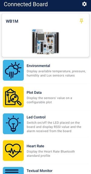
3.2.1. Home Page
Here is the main page where you can find all the features implemented with the embedded application.
Now let's have a look at all the implemented services:
- BLE Sensor (Environmental / Plot Data)
- p2pServer (Led Control)
- HeartRate
Click on any of them to discover more.
| ST BLE Sensor Features Page |
|---|
 |
3.2.2. HeartRate Service
In the HeartRate interface, Heart Rate and energy measurement are launched and displayed in graphs, you can reset the energy measurement.
For more information, click here : STM32WB_HeartRate
| HeartRate |
|---|

3.2.3. Led Control
In the LED control panel, you can turn the LED on and off for your board. Additionally, you can receive a notification by clicking on the board's button.
You can find more information about our Peer to Peer examples here: Peer_To_Peer
| Led Control |
|---|

3.2.4. Environmental and Motion Sensors
Now let’s have a look at the sensors panel.
For the environmental part you can find temperature and the humidity measured by the STTS22H [2] sensor of your WB1M.
Click the button in the top right to switch between units, from degrees to Fahrenheit.
| Environmental Sensor |
|---|

Regarding the Plot Data tab:
| Motion Sensor (1/2) |
|---|

| Motion Sensor (2/2) |
|---|

4. What Next ?
Now that you've familiarized yourself with the B-WB1M-WPAN1 and its out-of-the-box demo, it's time to take your experience to the next level. In this section, we'll show you where to find available code, how to flash your own code onto the board, and how to develop your own applications.
Get ready to unleash the full potential of your B-WB1M-WPAN1!
4.1. How can I program my WB1M board ?
The basic way to support an external debug tool is to connect the external STLINK-V3SET[3] debugger tool:
- to the debug connector CN3 of the MB1868 and,
- to a PC with a USB connector, as displayed below.
| Connecting an external debug tool to program the CEB MB1868 |
|---|

4.2. Start your own application
The STM32CubeWB MCU Package[4] provides software components running on STM32WB Series MCUs.
For all examples provided within the package, the following integrated development environments are supported:
- STMicroelectronics integrated development environment for STM32 products (STM32CubeIDE)
- IAR Systems® IAR Embedded Workbench® for Arm® (EWARM)
- Keil® Microcontroller Development Kit (MDK-ARM)
The Firmware Package for the STM32WB series is also available on STM32CubeWB github[5].
To learn more about the STM32WB Series MCUs or to go further based on available applications, click here.
5. References