1. X-CUBE-MATTER
1.1. What is X-CUBE-MATTER?
1.1.1. General description
The X-CUBE-MATTER expansion package provides software components for various STM32 microcontroller development platforms based on Arm® cores. A development platform consists of hardware, either a single board or a combination of two boards. The choice of platform depends on the target network access technology (Thread, Ethernet, Wi-Fi) and the type of Matter device (Matter end device, Matter bridge). Binaries are provided for quick demos.
Key features:
- Preintegrated Matter SDK: The X-CUBE-MATTER package includes the Matter SDK pre-integrated on STM32 microcontrollers. The Matter SDK middleware uses FreeRTOS™, mbedTLS infrastructure, and OpenThread stack. It serves as a reference implementation for demonstration and prototyping a Matter end-device on a reference development platform. Supported STM32 platforms are detailed in the associated wiki article.
- CSA certification ready: The package is ready for CSA certification with the default "dimmable light device type" and uses the MATTER OTA protocol to support firmware updates. Other device types are provided as prototypes for evaluation purposes. Refer to the X-CUBE-MATTER release note for any limitations on STM32 Matter device platforms.
- Embedded hardware blocks: The STM32 SoC includes most hardware blocks such as embedded Flash, crypto engine, RNG, and RTC. Connectivity technologies like Thread, Bluetooth® LE, Wi-Fi, and Ethernet are supported, either embedded in a standalone SoC or a chipset. Detailed information on supported technologies is available in the wiki article.
Security and Storage:
- Device Credentials and Keys: The project stores device credentials and keys in the STM32 embedded flash memory or an external flash memory, for which X-CUBE-MATTER provides a driver. It offers infrastructures from partners to provision a DAC private key into STM32 secure storage internal flash and provides a related driver for operational networks. Once provisioned, security-sensitive data and operations remain in a secure partition, isolated from the user application. Refer to the X-CUBE-MATTER release note for any limitations on STM32 Matter device platforms.
- Secure boot process: The secure boot process acts as a Root of Trust for the application before launching it. It ensures secure firmware updates once a new image is downloaded by the user application.
X-CUBE-MATTER is available for free download from [1] website.
1.1.2. X-CUBE-MATTER versions
The X-CUBE-MATTER versions contain software components and features that are continuously evolving. Refer to the release note included in the package for more details.
1.1.3. Software architecture
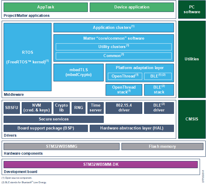
1.1.3.1. Overall block diagram
| X-CUBE-MATTER architecture block diagram |
|---|
1.1.3.2. Components description
The X-CUBE-MATTER software components consist of:
- Core Matter SDK Stack: From connectedhomeip.
- Files Generated by ZAPTool: And tools provided by connectedhomeip.
- FreeRTOS™, mbedTLS, and LwIP: Integrated into the package.
- Adaptation Layers: Either based on components from connectedhomeip but adapted, or modified by ST to run on the STM32 infrastructure.
Software Partitioning: The OpenThread stack, Bluetooth® LE stack, and IP stack can be located on the application MCU in the case of a chipset solution or on a dedicated wireless stack coprocessor. The software partitioning for each target platform is detailed in the associated wiki article.
Application examples: The delivered application examples as part of the project come with compiled binaries for an out of the box experience. Source codes are provided and can be compiled with supported IDEs. The project can be modified and regenerated using STM32CubeIDE. Release note for features supported in this version of X-CUBE-MATTER (Matter SDK version, supported applications, and their list of features) included in the package.
Low power framework: When embedded, the low power framework is implemented in the utilities component.
1.1.4. Folders structure
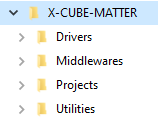
The X-CUBE-MATTER is compliant with STM32CubeFW folders that are drivers, middleware, projects, and utilities, as illustrated in the figure below.
| X-CUBE-MATTER folder structure: Main folders |
|---|
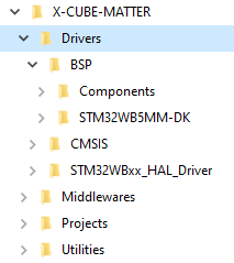
- Drivers folder
The Drivers folder contains the HAL drivers, the board-specific drivers for each supported board or hardware platform (including the onboard components), and the CMSIS vendor-independent hardware abstraction layer. These are STM32Cube firmware components.
| X-CUBE-MATTER Folder structure: Drivers |
|---|
- Middlewares folder
The Middleware folder contains two main subfolders:
- - ST subfolder, which contains:
- The ST67W6X Network Driver used to control the X-NUCLEO-67W61M1 expansion board associated with the NUCLEO-U575ZI-Q board. This middleware component provides the API to manage Wi-Fi, Bluetooth® LE, sockets, or system features in the Matter use case and transports messages between the host and the ST67W611M1 over the underlying bus via AT commands over the SPI interface.
- Security components used by SBSFU (STM32_Cryptographic, STM32_key_Management_Services, STM32_Secure_Engine) for X-CUBE-MATTER package version containing STM32WB55, and the STM32_WPAN (Bluetooth® LE, Thread) middleware components for the STM32WB platform.
- A security component (mbedtls_alt) used by the Matter stack, STM32WBA_WPAN middleware component, and OEMiROT for the STM32WBA platform.
- - Third-party subfolder which contains:
- The connectedhomeip source code, including the STM platform-specific code and the code generated with the ZAP Tool common to all clusters (zzz_generated\app-common\zap-generated). Each device/app subfolder contains the code generated with the ZAP Tool (devices<network interface technology><app>\zap-generated, where <network interface technology> is Thread or Wi-Fi for end devices, or Ethernet for bridge devices) for a given device type.
- The FreeRTOS™ and mbedtls components common to all platforms.
- The mcuboot component used by OEMiROT_Boot on the STM32WBA6 platform.
- The LwIP component used by the Matter stack over Ethernet on the STM32H7 or Wi-Fi on the STM32U575ZI with the ST67W611M1.
| X-CUBE-MATTER folder structure: Middlewares |
|---|
- Projects folder
The following figures represent different views of the X-CUBE_MATTER project that respectively show where applications and utilities needed to develop and prototype are located:
- - For STM32WBA65-DK1 platform:
- Matter applications that do not use TrustZone® are located in the
X-CUBE-MATTER\Projects\STM32WBA65I-DK1\Applications\Matterfolder. For each of these applications (Lighting-App, Window-App, and Generic-Switch-App), binaries for out-of-the-box quick demonstrations are delivered in the<App>\Binariessubfolder. - STM_Provisioning in
X-CUBE-MATTER\Projects\STM32WBA65I-DK1\Applications\Matteris the provisioning application for Matter applications that do not use TrustZone®. It can be used for device DAC and private key provisioning demonstrations and can be customized by Third-Party for secure provisioning during manufacturing. - ROT_Lighting_OEMiRoT project contains the Matter Lighting-App application that uses TrustZone® without TFM. Its subfolders OEMiROT_Appli_TrustZone and OEMiRoT_Boot contain respectively the applications (secure and non-secure) and the secure bootloader. The subfolder OEMiROT_Appli_TrustZone\Binary and its included binaries are not delivered in the package but are obtained after the build process.
- The ROT_Provisioning_Lighting_OEMiRoT folder contains OEMiROT features for ROT_Lighting_OEMiRoT: output binaries and generated images in OEMiROT/Binary, OEMiROT configuration files in OEMiROT/Config, keys for firmware image authentication and encryption in OEMiROT/Keys, image configuration files in
OEMiROT/Images, and device provisioning (firmware programming) scripts for OEMiROT TrustZone applications. These scripts can be used to directly program the device with the Lighting-App application with OEMiRoT for testing but not during factory provisioning, in which case the application is programmed using the OTA mechanism which replaces the provisioning application with this operational application. - ROT_Lighting_TFM project contains the Matter Lighting-App application that uses TrustZone® and TFM. Its subfolders OEMiROT_Appli_TrustZone and OEMiRoT_Boot contains respectively the applications (secure and non-secure) and the secure bootloader. The subfolder
OEMiROT_Appli_TrustZone\Binaryand its included binaries are not delivered in the package but are obtained after the build process. - ROT_Provisioning_Lighting_TFM folder contains OEMiROT features for ROT_Lighting_TFM: output binaries and generated images in
OEMiROT/Binary, OEMiROT configuration files in OEMiROT/Config, keys for firmware image authentication and encryption inOEMiROT/Keys, image configuration files inOEMiROT/Images, and device provisioning (firmware programming) scripts for OEMiROT TrustZone applications. These scripts can be used to directly program the device with the Lighting-App application with OEMiRoT and TFM for testing but not during factory provisioning, in which case the application is programmed using the OTA mechanism which replaces the provisioning application with this operational application. - ROT_STM_Prov_OEMiRoT folder contains the provisioning application for Matter Lighting-App application that uses TrustZone® without TFM. Its subfolders OEMiROT_Appli_TrustZone and OEMiRoT_Boot contains respectively the provisioning applications (secure and not secure) and the secure boot loader. The subfolder OEMiROT_Appli_TrustZone\Binary and its included binaries are not delivered in the package but are obtained after the build process.
- ROT_Provisioning_STM_Prov_OEMiRoT folder contains OEMiROT features for ROT_STM_Prov_OEMiRoT: output binaries and generated images in OEMiROT/Binary, OEMiROT configuration files in OEMiROT/Config, keys for firmware image authentication and encryption in
OEMiROT/Keys, image configuration files inOEMiROT/Images, and device provisioning (firmware programming) scripts for OEMiROT TrustZone applications. - ROT_STM_Prov_TFM folder contains the provisioning application for Matter Lighting-App application that uses TrustZone® and TFM. Its subfolders OEMiROT_Appli_TrustZone and OEMiRoT_Boot contains respectively the provisioning applications (secure and not secure) and the secure boot loader. The subfolder
OEMiROT_Appli_TrustZone\Binaryand its included binaries are not delivered in the package but are obtained after the build process. - ROT_Provisioning_STM_Prov_TFM folder contains OEMiROT features for ROT_STM_Prov_TFM: output binaries and generated images in
OEMiROT/Binary, OEMiROT configuration files inOEMiROT/Config, keys for firmware image authentication and encryption inOEMiROT/Keys, image configuration files inOEMiROT/Images, and device provisioning (firmware programming) scripts for OEMiROT TrustZone applications.
- Matter applications that do not use TrustZone® are located in the
| X-CUBE-MATTER folder structure: Projects - End device app without OEMiROT on STM32WBA6 |
|---|
| X-CUBE-MATTER folder structure: Projects - End device ROT app on WBA6 |
|---|
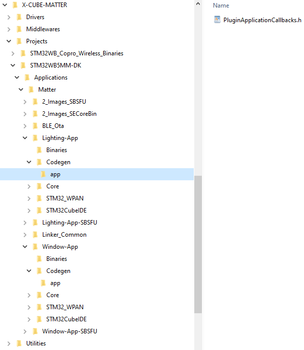
- - For STM32WB5MM-DK platform:
- The binaries (under
X-CUBE-MATTER\Projects\STM32WB_Copro_Wireless_Binariessubfolder) used to program the M0 core of STM32WB5x based platforms - The key used to decrypt the .sfb binary file received from the OTA provider during the software upgrade procedure. It is located in the
\2_Images_SECoreBin\Binaryfolder - The binary of the Matter application stored in the
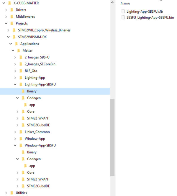
X-CUBE-MATTER\Projects\STM32WB5MM-DK\Applications\Matter\”App”\Binariessubfolder of each application. It is used to program the M4 core for an out-of-the-box quick demonstration. - The binaries of the Matter application with SBSFU (SBSFU_"App"-SBSFU.bin and "App"-SBSFU.sfb) in
X-CUBE-MATTER\Projects\STM32WB5MM-DK\Applications\Matter\Window-App-SBSFU\Binarysubfolder of each application and to be used to program the M4 core are generated after build process. - The embedded application (STM_Provisioning) provided for device provisioning demonstration and that can be customized by Third-Party for secure provisioning during manufactoring.
- The binaries (under
| X-CUBE-MATTER folder structure: Projects - End device coprocessor on STM32WB5 |
|---|
| X-CUBE-MATTER Folder structure: Projects - End device application without SBSFU on STM32WB5 |
|---|
| X-CUBE-MATTER folder structure: Projects - End device application with SBSFU on STM32WB5 |
|---|
- - For NUCLEO-H753ZI platform:
- The STM32CubeIDE Bridge-App project (.cproject and .project files) in the folder
X-CUBE-MATTER\Projects\NUCLEO-H753ZI\Applications\Matter\Bridge-Appfolder - The application specific part (sources files) in the
X-CUBE-MATTER\Projects\NUCLEO-H753ZI\Applications\Matter\Bridge-App\Appfolder and subfolder
- - Under
Bridge-App\App: application initialization and start, console management, monitoring status, non-volatile memory implementation, monitoring status, ... - - Under
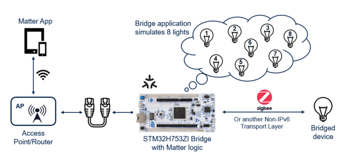
Bridge-App\App\bridge-app: bridge and bridged devices managementBridge-App\bridge-app\BridgedClustersManager.cpp: It declares and adds the six light devices supporting on-off cluster to the bridge (seeInit())Bridge-App\bridge-app\Device.cpp: it manages a device instance; as an example, when status "onoff" changes (seeSetOnOff()), displays the trace ("Device[{name}]: {status}" with {name}= Light1 to Light6 and {status}= ON or OFF), and sends the frame using hlpuart1 ("Light{n}:{status}" with {n}= 1 to 6 and {status}= ON or OFF)
- The delivered binaries (
Bridge-App_debug.binandBridge-App_release.bin) of the bridge application stored in theX-CUBE-MATTER\Projects\NUCLEO-H753ZI\Applications\Matter\Bridge-App\Binaries\STM32CubeIDEfolder, for an out-of-the-box quick demonstration - The board specific part in the
X-CUBE-MATTER\Projects\NUCLEO-H753ZI\Applications\Matter\Bridge-App\Corefolder, with for exampleCore\Src\main.cpp: STM32 board initialization (seemain()) - the interfacing of LwIP with ethernet driver, and ethernet specific module in
X-CUBE-MATTER\Projects\NUCLEO-H753ZI\Applications\Matter\Bridge-App\LwIP
- The STM32CubeIDE Bridge-App project (.cproject and .project files) in the folder
| X-CUBE-MATTER folder structure: Projects - Bridge device application on NUCLEO-H753ZI - STM32CubeIDE Bridge-App project |
|---|
| X-CUBE-MATTER folder structure: Projects - Bridge device application on NUCLEO-H753ZI - Application specific sources |
|---|
| X-CUBE-MATTER folder structure: Projects - Bridge device application on NUCLEO-H753ZI - Delivered binaries |
|---|
| X-CUBE-MATTER folder structure: Projects - Bridge device application on NUCLEO-H753ZI - LwIP and Ethernet management |
|---|
- - For NUCLEO-U575ZI-Q with X-NUCLEO-67W61M1 platform:
- The binary of the Matter application stored in the
X-CUBE-MATTER\Projects\NUCLEO-U575ZI-Q\Applications\Matter\ST67W6X_Lighting-App\Binariessubfolder. It is used to program the application processor STM32U575ZI for an out-of-the-box quick demonstration. - The binaries and programing tools for the ST67W611M1 network coprocessor
- The binary of the Matter application stored in the
| X-CUBE-MATTER Folder structure: Projects - End device application on NUCLEO-H753ZI - |
|---|
| X-CUBE-MATTER folder structure: Projects - Binaries and programing tools for the ST67W611M1 network coprocessor |
|---|
- Utilities folder
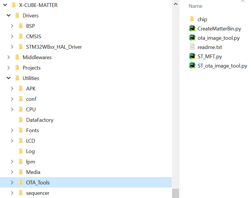
The OTA_Tools subfolder contains scripts provided in X-CUBE-MATTER for OTA firmware update over Matter. The subfolder chip within OTA_Tools contains functions coming fromconnectedhomeip\src\controller\python\chip\tlv and used by these scripts.
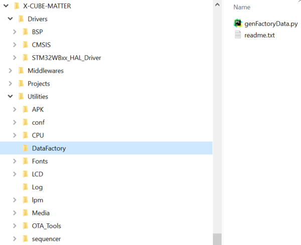
The DataFactory subfolder contains a programming PC tool for managing factory data during device testing or provisioning, along with a readme file explaining how to use the tool. For more details on this tool, refer to the dedicated wiki article Matter device factory data provisioning Matter device factory data provisioning.
| X-CUBE-MATTER folder structure: Utilities - OTA_Tools |
|---|
| X-CUBE-MATTER folder structure: Utilities - DataFactory |
|---|
1.2. Matter end devices (ED)
1.2.1. Customize the ED project
This demonstration uses applications delivered with X-CUBE-MATTER, but the user can do any needed customization (for example: modification of Bluetooth® LE discriminator) and recompile the project. For instructions on modifying the discriminator, refer to the section BLE discriminator modification
Follow the following steps:
STEP 1: Select the network interface technology (Thread®, Wi-Fi®)
STEP 2: Select an ED platform supporting the chosen network interface technology
STEP 3: Get the X-CUBE-MATTER
STEP 4: Customize the application and regenerate binary using STM32CubeIDE. From X-CUBE-MATTER v1.1.1, application customization can be also done using STM32CubeMx. The .ioc and .extSettings files are provided in each Matter application folder (X-CUBE-MATTER\Projects\<STM32 platform>\Applications\Matter\<App>). Currently, only STM32WB55 supports STM32CubeMX.
STEP 5: Program firmware (the generated one for the application and the delivered ones for a coprocessor core) into the platform cores as indicated in End devices and RCPs How To
STEP 6: From now, the device can be commissioned in Matter Fabric and ecosystems presented in Test and demonstrate.
1.2.2. Develop your own application
This section explains how to start developing your Matter device by generating cluster source files in the ZAP tool. One subsection is dedicated to installing the necessary tools. Then, integration into ST's X-CUBE-MATTER package is shown.
ZCL advanced platform (ZAP) is a code generation engine and user interface for applications and libraries based on a Zigbee Cluster Library, one of the specifications developed by CSA. On top of this, CSA provides a set of scripts and templates that modify this tool so that it can be used with the Matter standard instead of the original Zigbee one. See the X-CUBE-MATTER release notes for the correct ZAP tool version to be used.
1.2.2.1. Windows system setup for ZAP (one-time)
Before proceeding to work on a project, several tools need to be installed. These include the STM32CubeIDE to work with and compile the project, and the additional X-CUBE-MATTER package that is dedicated to Matter and contains examples and some ST-specific implementation.
These steps, as shown, have been tested on a Windows system. For Linux / MacOS, they are similar.
Install Python
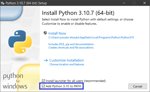
Install the latest version of Python 3.x. Python should be added to the system PATH.
Install Git
Another command-line interface can be used. For Git Bash, download and install from the Git website.
Download the connectedhomeip repository and the ZAP tool
- Create a folder [ConnectedHomeIP] where to store the connectedhomeip repository, for example “C:\chip-matter-tools”
- Download the repository from connectedhomeip with tag 1.4.0.0 and extract the content into the created folder [ConnectedHomeIP].
- The ZAP tool can be found here. The specific release needs to be compatible with the files included in the X-CUBE-MATTER package - [v2025.05.14 has been tested. Newer / older versions might generate source code which would not be possible to compile. Extract to a sub-folder of [ConnectedHomeIP] that could be named for instance “zap-win-x64”.
Environment configuration
Run Git Bash or another command-line interface as administrator. Make sure to update the Python pip component with the command:
python.exe -m pip install --upgrade pip
Then install all the necessary packages using pip:
pip install portalocker click lark jinja2 stringcase coloredlogs
It is advised to create a separate folder for files generated by ZAP, for example, C:\chip-matter-tools\zap_gen_files.
1.2.2.2. Starting project
After you generate the configuration files for your Matter device, you need to integrate them into a project. Currently, only Thread technology is supported in the examples. You can start from one of the examples available in the X-CUBE-MATTER package and modify the files similarly to how it is shown here. The projects can also be copied in place (into the same directory); this way, you can keep the original project and modify a copied version.
Basic functionality can be achieved based on the Lighting-App project. You can also use the project Lighting-App-SBSFU if you want update-over-the-air capability (#define OTA_SUPPORT needs to be set to 1). In all cases, the steps are very similar to what is described here.
1.2.2.3. Generate files in ZAP
In this section, we show how to set your device's clusters and export the basic code in ZAP. When integrated into a project, this code dictates how the device is seen by the Matter network. It also defines all of its basic functionality, which is specified by the standard. Run Git Bash or another command-line interface. Export the ZAP path to the environment with:
export ZAP_INSTALL_PATH=C:/chip-matter-tools/zap-win-x64
This need to be done at every Bash launch. Change to Matter directory, for example,
cd ../../C:/chip-matter-tools folder/connectedhomeip
and launch ZAP from here, starting from one of the example projects:
./scripts/tools/zap/run_zaptool.sh examples/light-switch-app/light-switch-common/light-switch-app.zap
Modify the project in the GUI according to your device needs and specifications:
- Select a device/endpoint from the device library specification.
- See which clusters are mandatory/optional for a given endpoint and enable them.
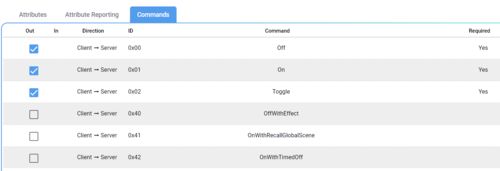
- For each cluster, there are also mandatory and optional attributes and commands. For example, long press for a generic switch.
| Optional cluster settings in ZAP | ||
|---|---|---|
|
|
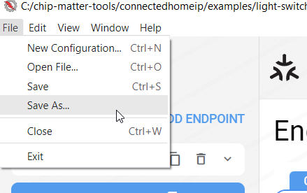
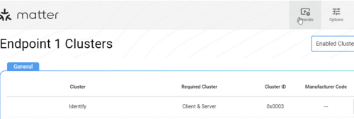
Save as a new file, for example, to C:\chip-matter-tools\zap_gen_files\my_light\light.zap. Then, click on the Generate button to produce source files. These files consist of generic ZAP templates for the device. Close the GUI but keep the Bash open.
| Save project and generate files in ZAP | ||
|---|---|---|
|
|
1.2.2.4. Matter code generation
Apart from the source files generated in the previous section, you also need to generate Matter-specific .c files. These files are used to expose Matter callbacks from each cluster to other clusters and to the user application, thus enabling communication between them.
In the Bash command line, convert the .zap file into a .matter one using the following:
python ./scripts/tools/zap/generate.py ../zap_gen_files/my_light/light.zap -o ../zap_gen_files/my_light/
and generate the two files containing callback definitions:
python ./scripts/codegen.py --generator cpp-app --output-dir ../zap_gen_files/my_light/ ../zap_gen_files/my_light/light.matter
1.2.2.5. Integrate code into STM32CubeIDE
Here, we add the generated cluster code and definitions from the previous section into a new X-CUBE-MATTER project.
In File explorer, navigate to the folder X-CUBE-MATTER\middlewares\Third_Party\connectedhomeip\devices\<network interface>. Copy the selected 'template' folder (one of the existing '...-app' folders) in here and rename it to my_light-app. Copy part of the files generated in the previous step into my_light-app\zap-generated (gen_config.h, endpoint_config.h, access.h, IMClusterCommandHandler.cpp) and part into my_light-app\zap-generated\app (PluginApplicationCallbacks.h, cluster-init-callback.cpp, callback-stub.cpp)
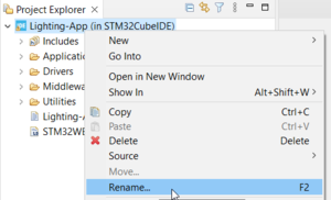
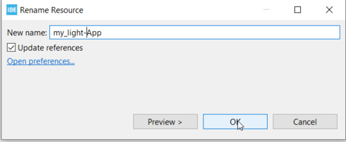
Keep open the target folders in file explorer for now. Open the project in STM32CubeIDE, rename it to my_light-app, and keep 'update references'.
| Rename the project | ||
|---|---|---|
|
|
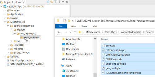
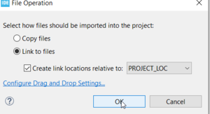
Open Middlewares\connectedhomeip\devices\Lighting-app\zap-generated, delete the existing files (which unlinks them from the project). Next, rename the 'Lighting-App' folder (under 'devices') to 'my_light-app'. Drag-and-drop the following files. Choose 'Link to files' and 'Create link locations relative to PROJECT_LOC'.
- access.h
- callback-stub.cpp
- cluster-init-callback.cpp
- endpoint_config.h
- gen_config.h
- IMClusterCommandHandler.cpp
- PluginApplicationCallbacks.h
| Copy the generated files | ||
|---|---|---|
|
|
Open the structure Middlewares\Third_Party\connectedhomeip\src\app\clusters in STM32CubeIDE and the folder X-CUBE-MATTER\Middlewares\Third_Party\connectedhomeip\src\app\clusters in the file explorer. Also, open the file PluginApplicationCallbacks.h that was copied before. For each callback in the .h file, check if the corresponding folder is included in STM32CubeIDE. If the needed subfolder is not present, follow these steps:
- Find the folder. For example, MatterBasicInformationPluginServerInitCallback corresponds to the basic-information subfolder.
- Drag and drop the folder from the file explorer into the
Middlewares\Third_Party\connectedhomeip\src\app\clusters\ folder in STM32CubeIDE. - Choose 'Link to files' and 'Create link locations relative to PROJECT_LOC'.
If there is a cluster subfolder that is not specified in PluginApplicationCallbacks.h, you can delete the cluster subfolder.
In the project properties (Alt+Enter), open C\C++ Build\Settings\MCU G++ Compiler\Include paths and modify (near the end of the list) Middlewares\Third_Party\connectedhomeip\devices\Lighting-app to Middlewares\Third_Party\connectedhomeip\devices\my_light-app.
1.2.2.6. Code modifications
Several device parameters (for example, name, serial number) can be changed as explained in How to customize your application. Functionality based on the target platform (second user button, LEDs, etc.) can also be added.
Application-specific functions should be modified to reflect the needs of your device. For this purpose, you can create new Manager.cpp and Manager.h files based on the LightingManager.cpp and LightingManager.h files. Then you need to update references to these files and functions in files like AppTask.cpp and ZclCallbacks.cpp. AppTask.cpp provides interaction between individual application components. ZclCallbacks.cpp serves as an interface between the Matter stack and your application. Callbacks defined here call the functions in the Manager.cpp file.
1.2.2.7. Program the application
After modifying the source files, you can generate the project in STM32CubeIDE. Then, program firmware (the generated one for the application and the delivered one for the coprocessor core) into the platform's cores as indicated in End devices and RCPs How To. From now, the device can be commissioned in the chosen Matter Fabric ecosystems presented in Test and demonstrate.
1.2.3. End device hardware platforms
1.2.3.1. Platforms supporting Thread technology
1.2.3.1.1. STM32 platforms used as Matter device
- STM32WBA65I-DK1 Discovery kit[1]
| STM32WBA65I-DK1 Discovery kit |
|---|
The USB cable (USB Type-A or USB Type-C® male to USB Type-C® male) from the PC is used to power and interact with the STM32.
Hardware configuration: Jumper JP4 on pins [1-2] to use the USB STLINK as the 5 V power source (this is the default configuration).
- STM32WB5MM-DK Discovery kit[2]
| STM32WB5MM-DK Discovery kit |
|---|
The USB cable (USB Type-A male to USB Type-B male) from the PC is used to power and interact with the STM32.
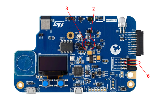
Hardware configuration: Jumper JP2 on pins [1-2] to use the USB STLINK as the 5V power source (this is the default configuration).
1.2.3.1.2. STM32 platforms used as RCP
- NUCLEO-WBA55CG Nucleo board[3]
| NUCLEO-WBA55CG Nucleo board |
|---|
The USB cable (USB Type-A or USB Type-C® to USB Type-C® cable) from the PC is used to power and interact with the STM32.
Hardware configuration: Jumper JP1 on pins [1-2] to use the USB STLINK as the 5V power source (this is the default configuration).
- NUCLEO-WB55RG Nucleo board[4]
| NUCLEO-WB55RG Nucleo board |
|---|
The USB cable (USB Type-A male to USB Type-B male) from the PC is used to power and interact with the STM32.
Hardware configuration: Jumper JP1 on pins [7-8] to use the USB STLINK as the 5V power source (this is the default configuration).
1.2.3.2. Platforms supporting Wi-Fi technology
1.2.3.2.1. NUCLEO-U575ZI nucleo board[5] with X-NUCLEO-67W61M1 expansion nucleo board[6] as network co-processor
The X-NUCLEO-67W61M1 must be plugged on the ARDUINO® Uno V3 connector of the NUCLEO-U575ZI-Q board as described in the X-NUCLEO-67W61M1 user manual.
| NUCLEO-U575ZI with X-NUCLEO-67W61M1 Nucleo boards |
|---|
The USB cable (USB Type-A male to USB Type-B male) from the PC is used to power and interact with the STM32.
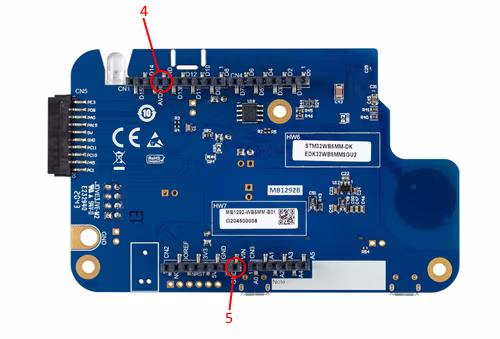
Hardware configuration: Jumper JP6 on pins [1-2] to use the USB STLINK as the 5V power source (this is the default configuration).
1.2.4. End devices and RCPs How To
This section covers both STM32 platforms used as Matter devices and those used as RCP.
1.2.4.1. How to program firmware on an STM32WBAx platform
1.2.4.1.1. How to program firmware on an STM32WBA6
The STM32WBA65I-DK1 platform is based on OEMiROT for secure boot and secure firmware updates. In X-CUBE-MATTER V1.5.0 OEMiROT project example is provided only for the Lighting-App application. All the code running on the STM32WBA6-based end device is delivered as source code and binaries for embedded application examples. To use your own application, use STM32CubeIDE to build it for STM32WBA65RI. There are two types of binaries delivered in X-CUBE-MATTER for the STM32WBA65I-DK1 platform out-of-the-box demonstration:
- Binaries without TrustZone for all embedded applications. These examples do not support OTA firmware updates,
- Binaries with TrustZone for Lighting-App application. This example supports OTA firmware updates.
1.2.4.1.1.1. How to program the firmware without TrustZone on STM32WBA65I-DK1
Use STM32CubeProgrammer to program the binary without TrustZone available in X-CUBE-MATTER\Projects\STM32WBA65I-DK1\Applications\Matter\<App>\Binaries folder at the start address: 0x0800 0000. <App> refers to the chosen application (Lighting-App, Window-App or Generic-Switch-App).
1.2.4.1.1.2. How to program the firmware with TrustZone (OEMiRoT enabled) without TFM on STM32WBA65I-DK1
- TrustZone binaries
The following binaries for secure and non-secure application parts are generated in X-CUBE-MATTER\Projects\STM32WBA65I-DK1\Applications\ROT_Lighting_OEMiRoT\OEMiROT_Appli_TrustZone\Binary folder for the Matter Lighting-App application and X-CUBE-MATTER\Projects\STM32WBA65I-DK1\Applications\ROT_STM_Prov_OEMiRoT\OEMiROT_Appli_TrustZone\Binary folder for Provisioning application, as illustrated in the Projects folder structure section of this article:
- -
oemirot_tz_ns_app.bin,oemirot_tz_ns_app_enc_sign.bin, andoemirot_tz_ns_app_init_sign.binfor the non-secure part (Matter application or Provisioning application). - - *
oemirot_tz_s_app.bin,oemirot_tz_s_app_enc_sign.bin, andoemirot_tz_s_app_init_sign.binfor the secure part (secure boot and secure firmware update).
The binaries oemirot_tz_x_app.bin, oemirot_tz_x_app_init_sign.bin, and oemirot_tz_x_app_enc_sign.bin are, respectively, the clear binary used to generate the two other signed ones, the signed and padded version for the first boot, and the signed and non-padded version for software updates (OTA).
- Binaries generation
STM32CubeIDE V1.18.0 is used to generate the TrustZone binaries by building the following two projects in sequence:
- OEMiROT_Boot project
- OEMiROT_Appli_TrustZone project, which consists of two sub-projects (OEMiROT_AppliTrustZone_NonSecure and OEMiROT_AppliTrustZone_Secure). Note that compiling the non-secure project automatically compiles the secure project being first.
At the end of the successful build process, six binaries (oemirot_tz_ns_app.bin, oemirot_tz_ns_app_enc_sign.bin, oemirot_tz_ns_app_init_sign.bin, oemirot_tz_s_app.bin, oemirot_tz_s_app_enc_sign.bin, and oemirot_tz_s_app_init_sign.bin) are generated and placed in the X-CUBE-MATTER\Projects\STM32WBA65I-DK1\Applications\ROT_Lighting_OEMiRoT\OEMiROT_Appli_TrustZone\Binary folder for the Matter Lighting-App application or in X-CUBE-MATTER\Projects\STM32WBA65I-DK1\Applications\ROT_STM_Prov_OEMiRoT\OEMiROT_Appli_TrustZone\Binary folder for the Provisioning application.
- PC scripts used to program TrustZone binaries
Two scripts (regression.bat and provisioning.bat, or regression.sh and provisioning.sh in Linux) are delivered in the X-CUBE-MATTER\Projects\STM32WBA65I-DK1\ROT_Provisioning_Lighting_OEMiRoT\OEMiROT folder for the Matter application direct programming, or in the X-CUBE-MATTER\Projects\STM32WBA65I-DK1\ROT_Provisioning_STM_Prov_OEMiRoT\OEMiROT folder for the Provisioning application direct programming. These scripts are used to program the firmware on the device.
- - regression.bat/sh script
- This script performs the full regression of the device. It prepares the device by setting the relevant values of option bytes, such as the write protection byte, and activates the TrustZone. It must always be executed before the
provisioning.bat/shscript (for example, to program a new image). - The following figures show the start of the regression script (from the
Projects/STM32WBA65I-DK1/ROT_Provisioning_Lighting_OEMiRoT/OEMiROTfolder) and its successful execution.
| regression.sh script - Start |
|---|
| regression.sh script - Successful end |
|---|
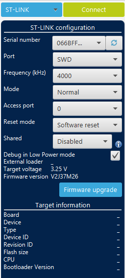
- STEP 1: Launch STM32_CubeProgrammer, set the ST-LINK "Mode" to "Hot plug" and connect to the STM32 board
| STM32_CubeProgrammer - WBA6 board connection in mode hot plug |
|---|
- STEP 2: Verify the following "Options Bytes" values. If they are not correct, update them and click “Apply”.
| STM32_CubeProgrammer - Correct Option Bytes configuration for Secure Area 1 |
|---|
| STM32_CubeProgrammer - Correct Option Bytes configuration for Write Protection 1 |
|---|
| STM32_CubeProgrammer - Correct Option Bytes configuration for Secure Area 2 |
|---|
| STM32_CubeProgrammer - Correct Option Bytes configuration for Write Protection 2 |
|---|
- - provisioning.bat/sh
- This script performs the actual device programming process. It writes the secure and non-secure firmware at the right place in the internal flash memory.
- The following figures show the start of the regression script (from the Projects/STM32WBA65I-DK1/ROT_Provisioning_Lighting_OEMiRoT/OEMiROT folder) and its successful execution.
| provisioning.sh script - Start |
|---|
| provisioning.sh script - Successful end |
|---|
1.2.4.1.1.3. How to program the firmware with TrustZone (OEMiRoT enabled) and TFM on STM32WBA65I-DK1
- TrustZone binaries
The following binaries for secure and non-secure application parts are generated in X-CUBE-MATTER\Projects\STM32WBA65I-DK1\Applications\ROT_Lighting_TFM\OEMiROT_Appli_TrustZone\Binary folder for the Matter Lighting-App application and X-CUBE-MATTER\Projects\STM32WBA65I-DK1\Applications\ROT_STM_Prov_TFM\OEMiROT_Appli_TrustZone\Binary folder for Provisioning application, as illustrated in the Projects folder structure section of this article:
- -
oemirot_tz_ns_app.bin,oemirot_tz_ns_app_enc_sign.binandoemirot_tz_ns_app_init_sign.binfor the non-secure part (Matter Lighting-App application). These binaries are respectively the clear binary used to generate the two other signed ones, the signed and padded version for first boot, and the signed and non-padded version for software update (OTA). - -
oemirot_tz_s_app.bin,oemirot_tz_s_app_init_sign.binandtfm_s_ota.binfor the secure part (TFM secure boot secure firmware update). These binaries are respectively the non-signed TFM binary, the TFM signed binary and the flash memory part for OTP_NV_COUNTER-PS-ITS (One-Time Programmable Non-Volatile Counter, Protected Storage, Internal Trusted Storage) used by TFM binary. The OTP NV COUNTER area is used to store security counters, typically for anti-rollback protection. The PS area is used to securely store user or application data that requires confidentiality and integrity. The ITS area is used for Matter by TFM to store the DAC private key.
- Binaries generation
- - Non-secure binaries generation
- STM32CubeIDE V1.18.0 is used to generate the non-secure TrustZone binaries by building the following two projects sequentially:
- OEMiROT_Boot project
- OEMiROT_Appli_TrustZone project
- At the end of the successful build process, three non-secure binaries are generated:
oemirot_tz_ns_app.binoemirot_tz_ns_app_enc_sign.binoemirot_tz_ns_app_init_sign.bin
- These binaries are placed in the following directories:
- Matter Lighting-App application:
X-CUBE-MATTER\Projects\STM32WBA65I-DK1\Applications\ROT_Lighting_TFM\OEMiROT_Appli_TrustZone\Binary - Provisioning application:
X-CUBE-MATTER\Projects\STM32WBA65I-DK1\Applications\ROT_STM_Prov_TFM\OEMiROT_Appli_TrustZone\Binary
- Matter Lighting-App application:
- - Secure binaries (TFM) generation
- The TFM binaries are generated as follow:
- 1. Install required tools
- Follow the Trusted Firmware Getting Started page to install all necessary tools. During the process, CMake and Ninja are used as the build system.
- 2. Clone TFM repository
- Assuming the user is using a Windows PC, the
C:\WBA6directory, and a Git Bash shell:- Open Git Bash shell.
- Create the
C:\WBA6directory:mkdir WBA6. - Navigate to the
C:\WBA6directory:cd WBA6. - Clone the TFM repository:
git clone https://review.trustedfirmware.org/TF-M/trusted-firmware-m.
- 3. Select the correct version and apply patches for Matter application
- Select the SHA1 used and tested by STMicroelectronics for the Matter application:
SHA1 = b9ef3b259b. - Apply the ST patches: Unzip the
Utilities\TFM\TFM-Matter-patch.zipfile inC:\WBA6. Four files will be overwritten.
- Select the SHA1 used and tested by STMicroelectronics for the Matter application:
- 4. Build TFM for Matter binaries
- In the
C:\WBA6directory, execute the following commands:cmake -S ./trusted-firmware-m -B ./build_s -GNinja -DTFM_PLATFORM=stm/stm32wba65i_dk -DTFM_TOOLCHAIN_FILE=$WBA6_tfm_src/toolchain_GNUARM.cmake -DCMAKE_BUILD_TYPE=Release -DTFM_ISOLATION_LEVEL=2 -DTFM_PROFILE=profile_large
cmake --build ./build_s -- install
- The
build_sdirectory is created parallel to thetrusted-firmware-mdirectory and populated. - Note: To compile the TFM in Debug mode, change the
–DCMAKE_BUILD_TYPEoption fromReleasetoDebug. - The two binaries generated are located in
C:\WBA6\build_s\api_ns\bin\:tfm_s_fmw.bin: The TFM binary, which must be renamed and signed.tfm_s_otp.bin: The flash memory part forOTP_NV_COUNTER-PS-ITSused by the TFM binary. This file is used as is.
- 5. Import TFM-Matter binaries to X-CUBE-MATTER ecosystem
- Copy
tfm_s_otp.binto:\Projects\STM32WBA65I-DK1\Applications\ROT_TFM\OEMiROT_Appli_TrustZone\Binary\. - Copy
tfm_s_fwm.binto:\Projects\STM32WBA65I-DK1\Applications\ROT_TFM\OEMiROT_Appli_TrustZone\Binary\. - Rename
tfm_s_fwm.bintooemirot_tz_s_app.bin.
- Copy
- 6. Sign the binary
oemirot_tz_s_app.bin - Use the Trusted Package Creator included in the STM32CubeProgrammer installation and proceed as follows:
- Select the XML file:
ROT_Provisioning_Lighting_TFM\OEMiROT\Images\OEMiROT_S_Code_Init_Image.xml. - Press the "Generate Image" button to generate the file
oemirot_tz_s_app_init_sign.bin.
- Select the XML file:
- 6. Sign the binary
- After signing the Secure Application (TFM), the final set of TrustZone binaries is as shown in the following picture:
- PC scripts used to program TrustZone binaries
Two scripts (regression.bat and provisioning.bat, regression.sh and provisioning.sh in Linux) delivered in X-CUBE-MATTER\Projects\STM32WBA65I-DK1\ROT_Provisioning_Lighting_TFM\OEMiROT folder for the Matter application direct programming, or in X-CUBE-MATTER\Projects\STM32WBA65I-DK1\ROT_Provisioning_STM_Prov_TFM\OEMiROT folder for the Provisioning application programming, are used to program the firmware on the device.
- - regression.bat/regression.sh script
- This script performs the full regression of the device. It prepares the device by setting the relevant values of options bytes such as the write protection byte and activate the TrustZone. It must always be executed before the
provisioning.bat/provisioning.sh(for example, to program a new image). - The following figures show the start of the regression script (from the
X-CUBE-MATTER\Projects\STM32WBA65I-DK1\ROT_Provisioning_Lighting_TFM\OEMiROTfolder) and its successful execution.
| regression.bat script - Start |
|---|
| regression.bat script - Successful end |
|---|
- STEP 1: Launch STM32_CubeProgrammer, set the ST-LINK "Mode" to "Hot plug" and connect to the STM32 board
| STM32_CubeProgrammer - WBA6-TFM board connection in mode hot plug |
|---|
- STEP 2: Verify the following "Options Bytes" values. If they are not correct, update them and click “Apply”.
| STM32_CubeProgrammer - Correct Option Bytes configuration for Secure Area 1 |
|---|
| STM32_CubeProgrammer - Correct Option Bytes configuration for Write Protection 1 |
|---|
| STM32_CubeProgrammer - Correct Option Bytes configuration for Secure Area 2 |
|---|
| STM32_CubeProgrammer - Correct Option Bytes configuration for Write Protection 2 |
|---|
- - provisioning.bat/provisioning.sh script
- This script performs the actual device programming process. It writes the secure and non-secure firmware at the right place in the internal flash memory.
- The following figures show the start of the regression script (from the
X-CUBE-MATTER\Projects\STM32WBA65I-DK1\ROT_Provisioning_Lighting_OEMiRoT\OEMiROTfolder) and its successful execution.
| provisioning.bat script - Start |
|---|
| provisioning.bat script - Successful end |
|---|
1.2.4.1.2. How to program the NUCLEO-WBA55CG as RCP
To program the NUCLEO-WBA55CG platform, generate the RCP binary (not included in any X-CUBE-MATTER delivery) using STM32CubeWBA, and use STM32CubeProgrammer to program the Arm® Cortex®-M33 CPU at the start address: 0x0800 0000. For the RCP binary generation:
- Download the STM32CubeWBA firmware from st.com.
- Go to the Thread_RCP directory (
STM32Cube_FW_WBA_V.../Projects/NUCLEO-WBA55CG/Applications/Thread/Thread_RCP). - Choose your preferred code generation platform (for example, STM32CubeIDE) and use it to generate the Thread_RCP binary.
1.2.4.2. How to program firmware on an STM32U575ZI with ST67W611M1 platform
The ST67W611M1 is programmed through the ST-LINK of the NUCLEO-U575ZI-Q and the SPI interface between the NUCLEO-U575ZI-Q and the X-NUCLEO-67W61M1. The programming setup is depicted in the figure below.
| ST67W611M1 programming hardware setup |
|---|
For more details on this setup and the programming process, refer to the X-NUCLEO-67W61M1 user manual.
Follow the steps below to program the network co-processor (NCP) ST67W611M1 and the host processor STM32U575ZI:
- Install STM32CubeProgrammer on the programming PC.
- Physically connect the NUCLEO-H753ZI board to the programming PC using a USB cable (standard A male port to micro-B male port) from the PC to the board's ST-LINK port to power and interact with the NUCLEO-U575ZI-Q board.
- Program the ST67W611M1 as follows: Open a command-line terminal and launch the batch file (NCP_update_mission_profile_t02.bat for Windows or NCP_update_mission_profile_t02.sh for Linux) delivered in
X-CUBE-MATTER\Projects\ST67W6X_Utilities\Binaries. The batch file automates the programming process. It relies on the QConn_Flash tool delivered inX-CUBE-MATTER\Projects\ST67W6X_Utilities\Binaries\QConn_Flashand the STM32CubeProgrammer tool (default path:C:/Program Files/STMicroelectronics/STM32Cube/STM32CubeProgrammer/bin). It uses binaries delivered inX-CUBE-MATTER\Projects\ST67W6X_Utilities\Binaries\NCP_BinariesandX-CUBE-MATTER\Projects\ST67W6X_Utilities\Binaries\NUCLEO-U575ZI-Q_Binaries. Refer to the NUCLEO-H753ZI Projects folder in the section Folders structure for the full picture of how ST67W611M1 is embedded in X-CUBE-MATTER. - Open the STM32CubeProgrammer on the programming PC.
- Program the STM32U575ZI with the binary
ST67W6X_Lighting-App.binat the start address: 0x0800 0000.- The ready-to-use binary is delivered in
X-CUBE-MATTER\Projects\NUCLEO-U575ZI-Q\Applications\Matter\ST67W6X_Lighting-App\Binaries. - A recompiled binary will be located in
X-CUBE-MATTER\Projects\NUCLEO-U575ZI-Q\Applications\Matter\ST67W6X_Lighting-App\STM32CubeIDE\{Debug or Release}for builds in Debug or Release mode, respectively. - If the ST67W611M1 is reprogrammed after the STM32U575ZI is programmed, the STM32U575ZI must be reprogrammed again.
- The ready-to-use binary is delivered in
1.2.4.3. How to program firmware on an STM32WB5x platform
The STM32WB combines an Arm Cortex®-M4 for the application, plus a 2.4 GHz radio subsystem and an Arm Cortex®-M0+ processor running the firmware upgrade service (FUS) and the wireless stack (Bluetooth® LE - Thread for Matter application).
Programming the STM32WB5x involves updating the FUS if needed and programming the two CPU cores (M0+ first, then M4).
If the M0 is reprogrammed after the M4 is programmed, the M4 must be reprogrammed again. Refer to the sections dedicated to the programming of those cores: How to program the M0+ and How to program the M4.
Before starting FUS, M0, and M4, check if the STLINK firmware version is the latest and upgrade if needed using STM32CubeProgrammer[7].
In the Matter context:
- NUCLEO-WB55RG or NUCLEO-WBA55CG is used as a radio coprocessor (RCP) that could be combined with an STM32MP1 to form an OTBR.
- STM32WB5MM-DK is used as a Matter end device.
1.2.4.3.1. How to program the M0+ core
All the code running on Arm Cortex®-M0+ is delivered as an encrypted binary, and it is necessary to upgrade the wireless stack before developing a project on the application side.
The STM32WB is preloaded with root security system firmware (firmware update service FUS) necessary to authenticate the selected wireless stack (binary encrypted format) loaded by the customer on st.com. If the out-of-the-box embedded version of the FUS is not the latest one, the FUS must be updated.
The firmware upgrade service (FUS) and Bluetooth® LE - Thread wireless stack can be updated using STM32CubeProgrammer software[7]. More information about the FUS can be found on the dedicated Firmware Upgrade Services wiki article. Alternatively, it can also be found within the firmware upgrade service for STM32WB series application note AN5185: FUS for STM32WB.
1.2.4.3.1.1 How to update the FUS
The FUS (firmware upgrade services) is a firmware that runs on STM32WB the Cortex®-M0+ and offers the following features:
- Install, upgrade, or delete STM32WB Cortex®-M0+ wireless stack
- FUS self-upgrade
- Customer authentication key management
- User key management
- Communication with Cortex®-M4 (user code or bootloader)
The steps described below are needed to update the FUS of NUCLEO-WB55RG and STM32WB5MM-DK Discovery platforms.
Open the release notes for STM32WB_Copro_Wireless_Binaries included in the downloaded X-CUBE-MATTER delivery: \STM32WB-Matter-BLE-Thread\Projects\STM32WB_Copro_Wireless_Binaries\STM32WB5x\Release_Notes.html.
Open the STM32CubeProgrammer[7] version indicated by the release notes.
Connect physically your development platform to the PC running STM32CubeProgrammer.
Connect your platform using STM32CubeProgrammer[7].
| STM32CubeProgrammer: connection |
|---|
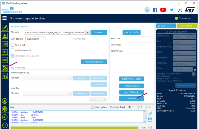
Start FUS
When connected, go to the firmware upgrade services interface, and start the FUS, by clicking on the associated button.
| STM32CubeProgrammer: start FUS |
|---|
Once the FUS has started correctly, the following logs should be visible on the STM32CubeProgrammer logs interface.
| STM32CubeProgrammer: FUS started logs |
|---|
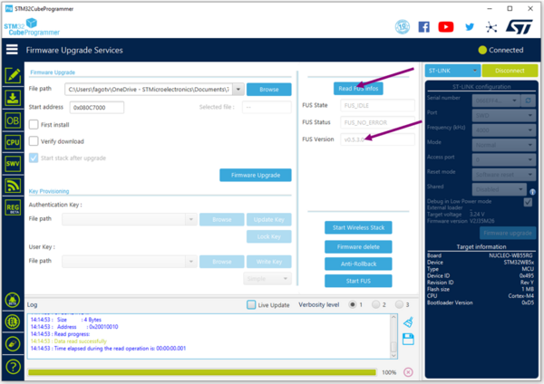
Read FUS
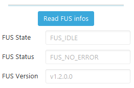
Once the FUS is started read its value by clicking the Read FUS infos button
| STM32CubeProgrammer: read FUS |
|---|
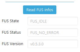
Update firmware upgrade service binary
The latest version of the FUS can be found in STM32CubeWB MCU package[8].
Start addresses and versions are given as an example. Check the release notes to find the latest FUS version and the FUS start address.
| FUS information |
|---|
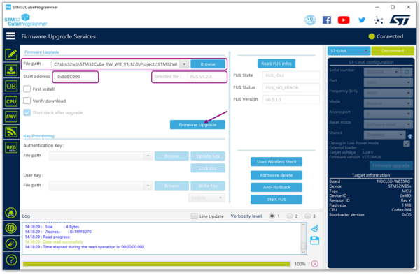
If the FUS version of your platform is different to the version specified in the release notes, proceed to the FUS update by following the steps below:
- If the platform FUS version is 0.5.3, use the dedicated binary:
STM32Cube_FW_WB_V[...]\Projects\STM32WB_Copro_Wireless_Binaries\STM32WB5x\stm32wb5x_FUS_fw_for_fus_0_5_3.bin
.
| STM32CubeProgrammer: FUS 0.5.3 |
|---|
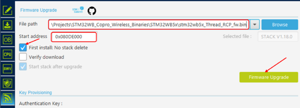
- If the platform FUS version is different to 0.5.3, then use the other binary: STM32Cube_FW_WB_V[...]\Projects\STM32WB_Copro_Wireless_Binaries\STM32WB5x\stm32wb5x_FUS_fw.bin
. Complete the file path with the correct file and add the start address (see release notes). Click on Firmware Upgrade.
| STM32CubeProgrammer: update FUS |
|---|
A popup appears to confirm that the upgrade is correct.
Check new FUS version
Check the new FUS version by clicking on the Read FUS info button.
| STM32CubeProgrammer: read new FUS |
|---|
1.2.4.3.1.2 How to update the coprocessor wireless stack (BLE-Thread or Thread RCP)
The Bluetooth® LE - Thread Stack (stm32wb5x_BLE_Thread_light_dynamic_fw.bin) for STM32WB5MM-DK, or the Thread stack for NUCLEO-WB55, can be updated in the same way as the FUS.
First, check the start address of the stack in the release notes within the X-CUBE-MATTER\Projects\STM32WB_Copro_Wireless_Binaries\STM32WB5x folder, for X-CUBE-MATTER version 1.0.X From X-CUBE-MATTER version 1.1.0 refer to STM32CubeWB for the start address of the stack
Note that the addresses in the pictures below are given for illustration but they can be different for different versions of software, so refer as indicated to the release note for actual addresses values.
| Stack start address |
|---|
Select the type of stack to be loaded :
- For NUCLEO-WB55 platform acting as an RCP the M0 stack to be used is generated from STM32CubeWB.
- For STM32WB5MM-DK Discovery platform acting as Matter End Device, the M0 stack to be used is:
X-CUBE-MATTER\Projects\STM32WB_Copro_Wireless_Binaries\STM32WB5x\stm32wb5x_BLE_Thread_light_dynamic_fw.bin.
Check the First install checkbox if it is the first time you are installing the stack on your platform.
| STM32CubeProgrammer: BLE-Thread stack installation |
|---|
| STM32CubeProgrammer: Thread stack installation |
|---|
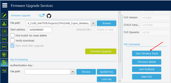
After having programmed the M0 and before programming the M4, ensure that the wireless stack is started by clicking on the Start Wireless Stack button.
| STM32CubeProgrammer: Start Wireless Stack |
|---|
1.2.4.3.2. How to program the M4 core
- Programming M4 on end device STM32WB5MM-DK
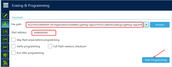
All the code running on the Arm Cortex®-M4 on end device is delivered as source code and binaries for embedded application examples. If you want to use your own application, use STM32CubeIDE to build it for M4. Use STM32CubeProgrammer to flash M4 with application at the start address: 0x0800 0000.
| STM32CubeProgrammer: Matter application installation |
|---|
- Programming M4 on NUCLEO-WB55RG as RCP
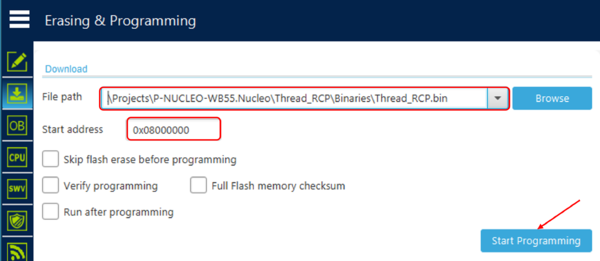
For RCP only the binary Thread_RCP.bin is delivered. Use STM32CubeProgrammer to program M4 with the delivered binary at the start address: 0x0800 0000.
| STM32CubeProgrammer: RCP M4 binary installation |
|---|
1.2.4.4. How to customize your end-device application
1.2.4.4.1. Bluetooth® LE discriminator modification
Modifying the Bluetooth® LE discriminator allows avoiding conflict when provisioning multiple end devices configured with the same discriminator. The procedure is as follow:
- Modify the default value
- - In
X-CUBE-MATTER\Projects\STM32WBA65I-DK1\Applications\Matter\XXX-App\Core\Inc\CHIPProjectConfig.hfor STM32WBA65I-DK1, orX-CUBE-MATTER\Projects\STM32WB5MM-DK\Applications\Matter\XXX-App\Matter\Inc\CHIPProjectConfig.hfor STM32WB5MM-DK, orX-CUBE-MATTER\Projects\NUCLEO-U575ZI-Q\Applications\Matter\ST67W6X_Lighting-App\Matter\Inc\STM32CHIPConfig.hfor NUCLEO-U575ZI-Q with X-NUCLEO-67W61M1, where XXX-App is the Matter application (for example Lighting-App), modify the value of the #define CHIP_DEVICE_CONFIG_USE_TEST_SETUP_DISCRIMINATOR. For example, replace the default value 0xF00 (3840 in decimal) with 0xA00 (2560 in decimal):
#define CHIP_DEVICE_CONFIG_USE_TEST_SETUP_DISCRIMINATOR 0xA00
:- In X-CUBE-MATTER\Projects\<STM32 platform>\Applications\Matter\XXX-App\STM32_WPAN\App\app_ble.c, where <STM32 platform> is the end device platform (for example, STM32WBA65I-DK1) and XXX-App is the application (for example Lighting-App), update the discriminator value in the a_AdvData table for STM32WBA65I-DK1, or in the manuf_data table for STM32WB55MM-DK (replace "0x00, 0x0F" with "0x00, 0x0A"):
uint8_t a_AdvData[15] = { 0x02, 0x01, 0x06, 0x0B, 0x16, 0xF6, 0xFF, 0x00, 0x00, 0x0A, 0xF1, 0xFF, 0x04, 0x80, 0x00, };
uint8_t manuf_data[15] = { 0x02, 0x01, 0x06, 0x0B, 0x16, 0xF6, 0xFF, 0x00, 0x00, 0x0A, 0xF1, 0xFF, 0x04, 0x80, 0x00, };
- Program the device with the Binary and reset the device
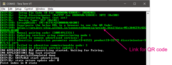
- Find the QR code link in the UART LOG and click on to show the new QR code.
Note: Currently, BLE Advertising data have to be updated manually to match with Factory Data (Discriminator, VendorID, ProductID).
1.2.4.4.2. End-device serial number modification
- Modify the default value
- STM32WBA65I-DK1 and STM32WB5MM-DK platforms:
- In
X-CUBE-MATTER\Projects\STM32WBA65I-DK1\Applications\Matter\XXX-App\Core\Inc\CHIPProjectConfig.hfor STM32WBA65I-DK1, orX-CUBE-MATTER\Projects\STM32WB5MM-DK\Applications\Matter\XXX-App\Matter\Inc\CHIPProjectConfig.hfor STM32WB5MM-DK, where XXX-App is the Matter application (for example Lighting-App), modify the value of the#define CHIP_DEVICE_CONFIG_TEST_SERIAL_NUMBER. - NUCLEO-U575ZI-Q with X-NUCLEO-67W61M1 platform:
- In
X-CUBE-MATTER\Projects\NUCLEO-U575ZI-Q\Applications\Matter\ST67W6X_Lighting-App\Matter\Inc\STM32CHIPConfig.hfor NUCLEO-U575ZI-Q, modify the value of the#define STM32_TEST_SERIAL_NUMBER(as#define CHIP_DEVICE_CONFIG_TEST_SERIAL_NUMBER STM32_TEST_SERIAL_NUMBERinX-CUBE-MATTER\Middlewares\Third_Party\connectedhomeip\src\platform\stm32\stm32u5\CHIPDevicePlatformConfig.h)
- Rebuild the project
- Program the device with the Binary and reset the device
1.2.4.5. How to perform remote firmware update (OTA) over Matter
1.2.4.5.1. Firmware update procedure overview
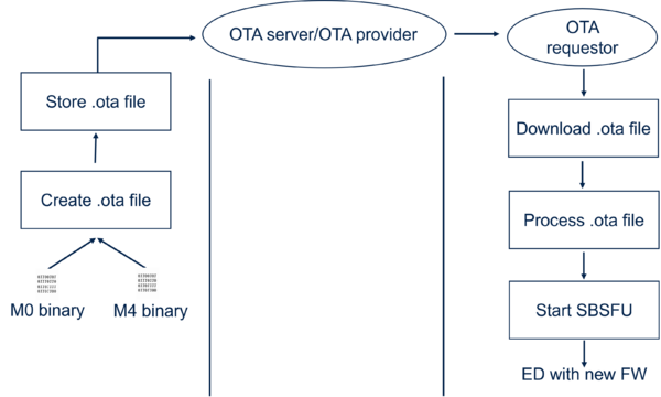
The following figure shows the update procedure from the .ota file preparation to the programming of the end device (ED) with the new firmware.
- First step: Generate the .ota file to be downloaded to the device
- Second step: Upload the .ota file to the OTA Provider
- Third step: The OTA provider announces the availability of new FW to OTA Requestor (ED). The ED download the .ota file using BDX protocol, processes the received .ota by copying on the fly it into
- - the external flash for WB55
- - the external or internal flash for WBA6 if respectively the EEPROM is or not used.
Once the file is fully copied to flash memory then the OTA requestor triggers the installation of the image(s) into the internal flash using the Secure FW update services.
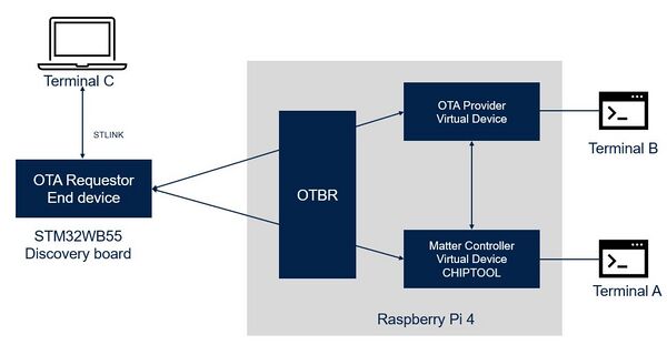
1.2.4.5.2. Firmware update environment overview
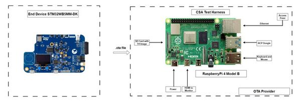
One can distinguish two environments corresponding respectively to a Raspberry Pi and an Android smartphone as OTA Provider.
- Raspberry Pi as OTA Provider
In this case, the OTA Provider and Matter Commissioner/Controller are virtual devices hosted on a Raspberry Pi 4. The OTA Provider is connected to Terminal B, and the Matter Controller, which uses CHIP Tool, is linked to Terminal A. These terminals serve as interfaces for monitoring and controlling the OTA process. The OTBR (Open Thread Border Router) sits at the center, connects the Thread network to “virtual” devices over Local IP-based network. The End device (e.g. STM32WBA65I-DK1 Discovery kit) serves as the OTA Requestor, connected to Terminal C via an STLINK.
1.2.4.5.3. Raspberry Pi preparation
For Raspberry Pi (including RCP dongle) setup procedure, follow CSA instructions given in the Matter Test-Harness User Manual
Note: How to SSH terminals from Raspberry Pi to PC to run the OTA.
- Make sure PC and Raspberry Pi are on the same network.
- 1. Enable the SSH server on Raspberry Pi
- a. Enter sudo raspi-config in a terminal window
- b. Select Interfacing Options
- c. Navigate to and select SSH
- d. Choose Yes
- e. Select Ok
- f. Choose Finish
- a. Enter sudo raspi-config in a terminal window
- 2. Check the ip address using the following command on Raspberry Pi
ifconfig
- 3. On the PC, open command prompt and use the following command
$ ssh <username>@<ip address>
- 4. Enter your account password when prompted.
You should now see the Raspberry Pi command prompt
1.2.4.5.4. How to generate the .ota file
1.2.4.5.4.1 How to generate the .ota file - STM32WBA6 based devices
STEP 1: New firmware version preparation
Matter over-the-air (OTA) on STM32WBA6 is based on OEMiROT project, which is a TrustZone application composed of:
- - A secure application started after boot process and responsible of the security configuration and the nonsecure application startup
- - A non-secure application that is the Matter application with minor adaptations for OTA. In X-CUBE-MATTER V1.5.0, the Lighting-App application is used as an example.
To prepare a firmware update, the firmware version needs to be increased for both OEMiROT and Matter.
- - OEMiROT version increase:
- Increment the field Version in the file X-CUBE-MATTER\Projects\STM32WBA65I-DK1\ROT_Provisioning_Lighting_OEMiRoT\OEMiROT\Images\OEMiROT_NS_Code_Image.xml (e.g. replace "<Value>1.0.0</Value>" by "<Value>2.0.0</Value>")
- - Matter version increase:
- Increment the define CHIP_DEVICE_CONFIG_DEVICE_SOFTWARE_VERSION in
X-CUBE-MATTER\Projects\STM32WBA65I-DK1\Applications\ROT_Lighting_OEMiRoT\OEMiROT_Appli_TrustZone\NonSecure\Core\Inc\CHIPProjectConfig.h(e.g. replace#define CHIP_DEVICE_CONFIG_DEVICE_SOFTWARE_VERSION 1by#define CHIP_DEVICE_CONFIG_DEVICE_SOFTWARE_VERSION 2), and the define#define X_CUBE_MATTER_VERSIONinX-CUBE-MATTER\Projects\STM32WBA65I-DK1\Applications\ROT_Lighting_OEMiRoT\OEMiROT_Appli_TrustZone\NonSecure\Core\Inc\app_entry.h(e.g. replace#define X_CUBE_MATTER_VERSION "v1.4.1_OEMIROT_v1by#define X_CUBE_MATTER_VERSION "v1.4.1_OEMIROT_v2)
STEP 2: Generate binaries
Generate the binaries as specified in section How to program firmware on an STM32WBAx platform.
STEP 3: Generate the .ota file
The update of the secure application is not supported in the current version of X-CUBE-MATTER, meaning that only the non-secure part will be updated. Only the signed not padded newly generated binary will be used for this purpose. Two Python scripts (CreateMatterBin.py and ota_image_tool.py) provided in X-CUBE-MATTER\Utilities\OTA_Tools are used .ota file generation:
- - CreateMatterBin.py
- This tool from STMicroelectronics is used in the first step to generate an intermediate binary by assembling a header and one or two binary files. In the current X-CUBE-MATTER version only one binary file (the non-secure application binary) is used.
- To run the python script, follow the below steps:
- Open Command Prompt on the PC.
- Browse to
X-CUBE-MATTER\Utilities\OTA_Toolsdirectory. - Run the below command.
python.exe ./CreateMatterBin.py -bin1 ...\X-CUBE-MATTER\Projects\STM32WBA65I-DK1\Applications\ROT\OEMiROT_Appli_TrustZone\Binary\oemirot_tz_ns_app_enc_sign.bin -o myMatter-fw.bin
Note: Make sure to include full path of the input binary. The output binary will use a default name if -o option is not used.
The output myMatter-fw.bin of this python script (default name if -o option is not used) is input to next tool.
The output file gets stored in X-CUBE-MATTER\Utilities\OTA_Tools folder
- -
ota_image_tool.py: this tool from CSA is used in a second step to add the matter header and produce the .ota file.- The output
myMatter-fw.binis used as input for this step to create the .ota file - To run the python script, follow the below steps:
- Open Command Prompt on the PC
- Browse to
X-CUBE-MATTER\Utilities\OTA_Toolsdirectory - Run the below command
- The output
python ./ota_image_tool.py create -v VENDOR_ID -p PRODUCT_ID -vn SOFTWARE_VERSION (newer or higher numerical(int)) -vs SOFTWARE_STRING_VERSION -da sha256 myMatter-fw.bin my-firmware1.ota
For example:
python ./ota_image_tool.py create -v 0xFFF1_ID -p 0x8004 -vn 2 -vs "v1.4.1_OEMIROT_v2" -da sha256 myMatter-fw.bin my-firmware1.ota
1.2.4.5.4.2 How to generate the .ota file - STM32WB55 based devices
STEP 1: Setting up the end device
This step describes the binaries and key to be used to support Matter OTA, and the preparation of the device on which to perform OTA.
For a device based on an STM32WB, there are two types of binaries:
- - One binary for an M0 core (in
X-CUBE-MATTER\Projects\STM32WB_Copro_Wireless_Binaries\STM32WB5x) - This is an encrypted binary provided by STMicroelectronics that contains the wireless stack. The key to decrypt it is used by FUS and stored in a secure part of the internal flash.
- - Two binaries available for an M4 core in
X-CUBE-MATTER\Projects\STM32WB5MM-DK\Applications\Matter\XXX-App-SBSFU\Binary:
SBSFU_XXX-App-SBSFU.bin, which is an unencrypted binary. This binary should be flashed for the very first Matter application. Refer to section How to program the M4 core for more information. It contains BLE_ota (aka Bluetooth® LE loader), secure engine, SBSFU, and the first version of the application.XXX-App-SBSFU.sfbis a encrypted binary to be programmed through SBSFU in internal flash during the firmware upgrade process. It contains the application (.bin) and its header used by an SBSFU process during M4 installation in internal flash. Before trying to upgrade the M4 application, the encryption/decryption key that has been used to encrypt this binary must be stored in the device. You can find the key in theX-CUBE-MATTER\Projects\STM32WB5MM-DK\Applications\Matter\2_Images_SECoreBin\Binaryfolder. To store the key in the device, use STM32CubeProgrammer.
- For firmware versioning, there are two different levels: Matter stack level and SBSFU level.
- Matter stack level
This firmware must be generated with a software version newer than the version in the firmware to be upgraded. The firmware version is set in the CHIPProjectConfig.h configuration file (#define CHIP_DEVICE_CONFIG_DEVICE_SOFTWARE_VERSION). A corresponding string (#define CHIP_DEVICE_CONFIG_DEVICE_SOFTWARE_VERSION_STRING) is also defined in this configuration file and is displayed in the UART log for result verification purposes. - SBSFU level
The firmware version is part of the firmware header generated with the postbuild script in IDE (X-CUBE-MATTER\Projects\STM32WB5MM-DK\Applications\Matter\2_Images_SECoreBin\STM32CubeIDE). It must be set to a value higher or equal to the version of the firmware to be replaced.
- Matter stack level
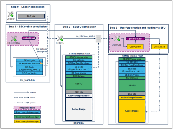
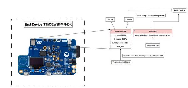
- For the generation of the binary, the following projects must be built in sequence to create the
SBSFU_XXX-App-SBSFU.binwith the current version to be loaded and provisioned with a decryption key required by SBSFU, using STM32CubeProgrammer. You can refer to "X-CUBE-MATTER\STM32WB5MM-DK\Applications\Matter\<Application>\Core\Inc\CHIPProjectConfig.h" to check the current software version of the Matter application. - 1.
X-CUBE-MATTER\Projects\STM32WB5MM-DK\Applications\Matter\BLE_Ota\STM32CubeIDE\.project - The BLE_Ota project implements the firmware download over BLE. It is not really used for OTA over Matter but is needed as it must be integrated into SBSFU and SBSFU_XXX-App-SBSFU.
- 2.
X-CUBE-MATTER\Projects\STM32WB5MM-DK\Applications\Matter\2_Images_SECoreBin\STM32CubeIDE\.project - The
2_Images_SECoreBinproject is used to generate the SE (Secure Engine) binary integrated into the SBSFU application. - 3.
X-CUBE-MATTER\Projects\STM32WB5MM-DK\Applications\Matter\2_Images_SBSFU\STM32CubeIDE\.project - The 2_Images_SBSFU project is used to generate the SBSFU application which manages secure boot and secure firmware upgrade.
- 4.
X-CUBE-MATTER\Projects\STM32WB5MM-DK\Applications\Matter\XXX-App-SBSFU\STM32CubeIDE\.project - The XXX-App-SBSFU project compilation step is used to generate
SBSFU_XXX-App-SBSFU.binandXXX-App-SBSFU.sfb. - The following image illustrates the compilation process described above.
| SBSFU: Binaries compilation process |
|---|
- The below flowchart explains the overall compilation and flashing process on the end device with Matter application.
- The
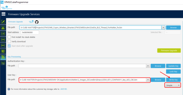
SBSFU_XXX-App-SBSFU.binfile (application: M4) is flashed on the end device with the M0 Stack (X-CUBE-MATTER\Projects\STM32WB_Copro_Wireless_Binaries\STM32WB5x\stm32wb5x_BLE_Thread_light_dynamic_fw.bin) and decryption key (X-CUBE-MATTER\Projects\STM32WB5MM-DK\Applications\Matter\2_Images_SECoreBin\Binary\OEM_KEY_COMPANY1_key_AES_CBC.bin) using the STM32CubeProgrammer.
- Program the STM32WB5MM-DK as a Matter device as explained in the section How to program the M4 core of this page but using the binary
SBSFU_XXX-App-SBSFU.binfor the M4 core. - In this context of firmware upgrade, the device must also be provisioned with a decryption key required by SBSFU, using STM32CubeProgrammer.
| STM32CubeProgrammer: SBSFU key provisioning |
|---|
- Your end device is all set to be updated with the newer software version of the Matter Application using the OTA process.
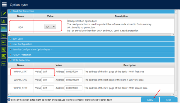
| Option bytes setting for non-protection mode |
|---|
STEP 2: Generate the .ota file
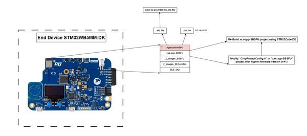
The below figure explains the process of creating the input file (.sfb) to generate the .ota file.
To create the .sfb file:
- In
X-CUBE-MATTER\Projects\STM32WB5MM-DK\Applications\Matter\<Application>\Core\Inc\CHIPProjectConfig.h - 1. Nowm set Software version and Software version string to a value higher to the version of the firmware to be replaced.
- For example:
- Modify the value of Software Version String:
- Modify the value of Software Version String:
- For example:
#define CHIP_DEVICE_CONFIG_DEVICE_SOFTWARE_VERSION_STRING "1.3"
- Modify the value of the Software Version:
- Modify the value of the Software Version:
#define CHIP_DEVICE_CONFIG_DEVICE_SOFTWARE_VERSION 3
- 2. Re-build only the X-CUBE-MATTER\Projects\STM32WB5MM-DK\Applications\Matter\XXX-App-SBSFU\STM32CubeIDE\.project.
- 3. After compilation, you will have the .bin and .sfb file in the
X-CUBE-MATTER\Projects\STM32WB5MM-DK\Applications\Matter\Window-App-SBSFU\Binary folder.
The generated xxx-app-SBSFU.sfb file is the input to generate the .ota file.
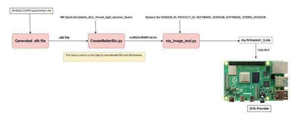
The .ota is generated in two steps using respectively the following two tools: The below block diagram shows the in depth two steps process to generate the .ota file.
The python scripts are found in (X-CUBE-MATTER\Utilities\OTA_Tools) folder.
- - CreateMatterBin.py
- This tool from STMicroelectronics is used in a first step to concatenate M0 and M4 binaries.
- This step takes .sfb file(xxx.sfb) as input with M0 stack and converts into .bin file
- To run the python script, follow the below steps:
- Open Command Prompt on the PC
- Browse to
X-CUBE-MATTER\Utilities\OTA_Toolsdirectory - Run the below command
python ./CreateMatterBin.py -m4 XXX-App-SBSFU.sfb -m0 stm32wb5x_BLE_Thread_light_dynamic_fw.bin -o myMatterM4M0-fw.bin
For example:
python ./CreateMatterBin.py -m4 ...\X-CUBE-MATTER\Projects\STM32WB5MM-DK\Applications\Matter\Window-App-SBSFU\Binary\Window-App-SBSFU.sfb -m0 ...\X-CUBE-MATTER\Projects\STM32WB_Copro_Wireless_Binaries\STM32WB5x\stm32wb5x_BLE_Thread_light_dynamic_fw.bin -o myMatterM4M0-fw.bin
Note: (Make sure to include full path for the Application(-m4) XXX-App.sfb and Stack(-m0) stm32wb5x_BLE_Thread_light_dynamic_fw.bin)
OUTPUT: The output of this python script is myMatterM4M0-fw.bin, and this file is input to next tool. The output file gets stored in (X-CUBE-MATTER\Utilities\OTA_Tools) folder
- - ota_image_tool.py: this tool from CSA is used in a second step to add the matter header and produce the .ota file.
- The output
myMatterM4M0-fw.binis used as input for this step to create the .ota file - To run the python script, follow the below steps:
- Open Command Prompt on the PC
- Browse to
X-CUBE-MATTER\Utilities\OTA_Toolsdirectory - Run the below command
- The output
python ./ota_image_tool.py create -v VENDOR_ID -p PRODUCT_ID -vn SOFTWARE_VERSION (newer or higher numerical(int)) -vs SOFTWARE_STRING_VERSION -da sha256 myMatterM4M0-fw.bin my-firmware1_3.ota
For Example:
python ./ota_image_tool.py create -v 0xFFF1 -p 0x8004 -vn 3 -vs "1.3" -da sha256 myMatterM4M0-fw.bin my-firmware1_3.ota
OUTPUT: The output of this python script is my-firmware1_3.ota. The output file gets stored in (X-CUBE-MATTER\Utilities\OTA_Tools) folder.
STMicroelectronics provide two wrappers of the above scripts:
- - ST_ota_image_tool.py that simplifies the ota_image_tool.py usage,
python .\ST_ota_image_tool.py -cc ...\X-CUBE-MATTER\Projects\STM32WB5MM-DK\Applications\Matter\XXX-App-SBSFU\Core\Inc\CHIPProjectConfig.h my-firmware.bin my-firmware.ota
- - ST_MFT.py (based on a PySimpleGui library) that brings GUI experience over CSA and STMicroelectronics script
python .\ST_MFT.py
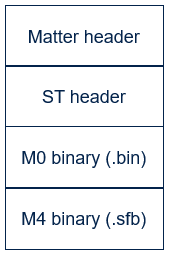
The .ota file is composed of two headers and two binaries as illustrated by the following figure:
1.2.4.5.5. Save the .ota file onto the device used as OTA provider
1.2.4.5.5.1. RaspberryPi as OTA provider
Save the .ota file onto the device used as OTA provider
The .ota file needs to be saved onto the RaspberryPi (TH) to run the OTA provider.
You can use the USB key to save the .ota file from the PC to RaspberryPi.
- 1. Copy .ota file on the USB key and Eject from PC.
- 2. Insert the USB key onto Raspberry Pi and access the files using the below mount commands.
sudo mkdir /mnt/usb
sudo mount /dev/sda1 /mnt/usb
ls -latr /mnt/usb (You can view the contents of the USB key)
- 3. Now, copy the .ota file from the USB key to apps directory present on Desktop using
cpcommand.
1.2.4.5.6. OTA file download
1.2.4.5.6.1. RaspberryPi as OTA provider
- 1. Terminal setup: Open two terminals on the RaspberryPi, Terminal A for the controlling the Matter Controller and Terminal B for controlling the OTA provider.
- On the PC, open terminal for the end device debug logging.
- 2. Terminal A: To get the "Thread network dataset", run the below command.
cd ~/chip-certification-tool/scripts/OTBR
sudo ./otbr_start.sh
- This step generates the hex code named “Simple Dataset”, make a note of the same.
- 3. Upload the .ota file to OTA Provider
- Terminal B: To start the OTA provider application and path it OTA file.
cd ~/apps
sudo ./chip-ota-provider-app -f my-firmware1_3.ota
- Keep the OTA provider running and return to Terminal A.
- 4. Switch back to Terminal A: Commission the OTA provider into network over IP using the user-defined node id "1" and the setup PIN code "20202021".
cd apps
sudo ./chip-tool pairing onnetwork 1 20202021
- 5. Write to the OTA provider access control cluster (node id 1, endpoint 0) the ACL data granting Operate privileges to all nodes in the fabric.
- This command is to prepare the OTA Provider to receive Cluster commands from all nodes of the fabric.
sudo ./chip-tool accesscontrol write acl '[{"fabricIndex":1, "privilege":5, "authMode":2, "subjects":[112233], "targets":null},{"fabricIndex":1,"privilege":3,"authMode":2,"subjects":null,"targets":null}]' 1 0
- Start end device (if not yet) in fast advertising mode by resetting the board.
- 6. Commission the end device using the following CHIP Tool command with respectively the following parameters: the node id 3, the "Thread network dataset" previously obtained in STEP 2, the setup PIN code 20202021, and the discriminator 3840.
sudo ./chip-tool pairing ble-thread 3 hex:"Thread network dataset" 20202021 3840
- Save provider information in NVM on end device.
- 7. Provide the Matter end device/OTA requestor (node id 3, endpoint- 0) with the list of default OTA providers that contains only one element (fabric index 1, node id 1, endpoint 0).
sudo ./chip-tool otasoftwareupdaterequestor write default-otaproviders '[{"fabricIndex":1, "providerNodeID":1,"endpoint":0}]' 3 0
- 8. Send the Announce OTA provider command to the device with the following parameters in the order: provider node id = 1, provider vendor id = 0, announcement reason = 0 for UpdateAvailable, provider endpoint = 0, requestor node = 3, requestor endpoint = 0.
sudo ./chip-tool otasoftwareupdaterequestor announce-otaprovider 1 0 0 0 3 0
- Once the device receives this announce, it requests the new software image.
- 9. Download and process the .ota file
- Observe the BDX (Bulk Data Exchange) transfer ON Terminal A and End Device Terminal (Terminal C).
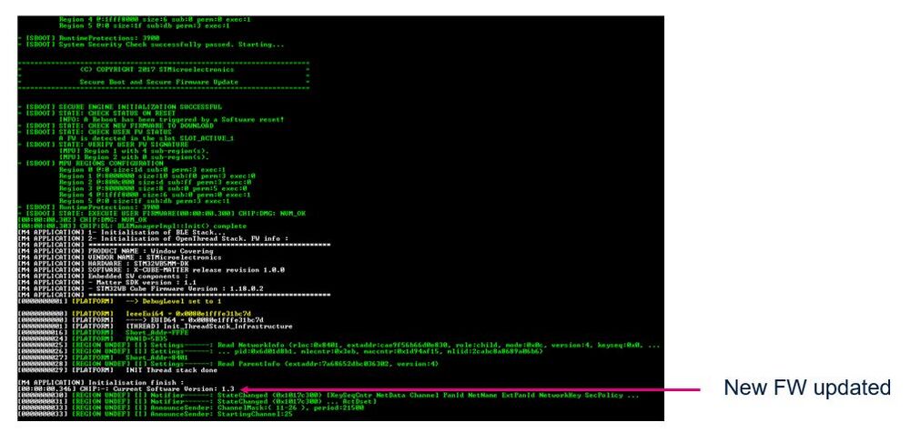
- Check that at the end of BDX transfer, the end device restarts correctly with the new firmware.
1.2.4.5.7. OTA execution on the device
1.2.4.5.7.1 OTA over Matter execution on STM32WBA65I-DK1 with OEMiRoT without TFM
From X-CUBE-MATTER V1.5.0, external flash memory (EEPROM M95P32) is supported for the STM32WBA65I-DK1. Consequently, for OTA execution, two scenarios must be considered: using both internal and external flash (4 MB) memories (this is the default configuration) or using only the internal flash (2 MB). Use of external flash will allow to build a DEBUG image (STM32CubeIDE debug mode), too large to fit in the internal flash, to debug the Matter application in. With the use of OEMiROT for STM32WBA65I-DK1, the specific procedure to configure the STM32CubeIDE in DEBUG mode for debugging the Matter application is provided at the end of this section.
- STM32WBA65I-DK1 OEMiROT flash memory layout configuration
The OEMiROT flash layout is configured in the file flash_layout.h located in the X-CUBE-MATTER\Projects\STM32WBA65I-DK1\Applications\ROT_Lighting_OEMiRoT\OEMiROT_Boot\Inc folder.
Hereafter are listed few important parameters defined for internal flash in this file in the scenario where the external flash is also used:
- - #define OEMIROT_EXTERNAL_FLASH_ENABLE to indicate that the external flash is enabled
- - #define FLASH_NS_PARTITION_SIZE (0x1C6000) to define the non-secure partition size when the external flash is enabled
- - #define FLASH_S_PARTITION_SIZE (0x06000) to define the secure partition size when the external flash is enabled
The above partitions size defined in the delivered example can be customized by the user when needed.
During the build process, the OEMiROT postbuild scripts generates automatically the following two headers in the folder X-CUBE-MATTER\Projects\STM32WBA65I-DK1\Applications\ROT_Lighting_OEMiRoT\OEMiROT_Appli_TrustZone\Secure_nsclib for non-secure application:
- -
appli_flash_layout.h - -
appli_region_defs.h
These two files contain the defines associated with memory mapping and must not be modified manually.
- STM32WBA65I-DK1 OTA configuration
To activate OTA in the Matter application, the two following compilation flags need to be defined in the file app_conf.h located in the X-CUBE-MATTER\Projects\STM32WBA65I-DK1\Applications\ROT_Lighting_OEMiRoT\OEMiROT_Appli_TrustZone\NonSecure\Core\Inc folder:
- -
#define OTA_SUPPORT (1) - -
#define OTA_EXTERNAL_FLASH_ENABLE (1) - The value of this flag must be aligned with the OEMIROT_EXTERNAL_FLASH_ENABLE flag in the OEMiROT_Boot project (flash_layout.h file)
- STM32WBA65I-DK1 internal flash memory layout
| STM32WBA65I-DK1 internal flash memory layout in internal with external flash use case (default) |
|---|
| STM32WBA65I-DK1 internal flash memory layout in internal without external flash use case |
|---|
| STM32WBA65I-DK1 external flash memory layout |
|---|
- Firmware update execution on STM32WBA65I-DK1 with OEMiRoT without TFM
- Upon .ota file downloaded, the OTA application performs the following operation:
- - Extracts and copies the TrustZone binary (oemirot_tz_ns_app_enc_sign.bin) in "Non-Secure Image Secondary Slot" (Area 3) of the flash memory (internal flash in the scenario without EEPROM or external flash in the scenario with EEPROM)
- - Pads and writes the correct magic number at the end of the slot and reset the device. This reset will start the OEMiROT_Boot which will proceed to the firmware update
- How to configure the STM32CubeIDE to debug the Matter application with OEMiROT on STM32WBA65I-DK1
As the DEBUG image is too large to fit in the internal FLASH, the support of the external is required to be able to debug the Matter application with OEMiROT.
Note: The debugger does not load images into the board. The images must have been previously loaded using the provisioning script.
The following procedure will be performed to configure the STM32CubeIDE to debug the Matter application:
- Select the OEMiROT_Boot project and in Run menu, select Debug As -> STM32 C/C++ application. This will open an "Edit Configuration" window.
- In the "Edit Configuration" window, select the "Main" tab and check the "Disable auto build" option.
- In the "Edit Configuration" window, select the "Startup" tab then add and configure the non-secure and secure application (initial configuration state).
- In the "Edit Configuration" window -> "Startup" tab, add the non-secure application configuration.
- Select "Add" button and add non-secure application (OEMiROT_Appli_TrustZone_NonSecure) in the "Project" field
- Uncheck "Perform build" option: -Uncheck "Download" option
- Press "OK"
- In the "Edit Configuration" window -> "Startup" tab, add the secure application configuration
- Select "Add" button and add the secure application (OEMiROT_Appli_TrustZone_Secure) in the "Project" field
- Uncheck "Perform build" option
- Uncheck "Download" option
- Press "OK"
- In the "Edit Configuration" window -> "Startup" tab, edit the OEMiROT_Boot project properties
- Select the "Edit" button and modify the OEMiROT boot application (OEMiROT_boot) configuration
- Uncheck "Download" option
- Press "OK"
- In the "Edit Configuration" window -> "Startup" tab, reorganize projects order
- Use "Move Up" and "Move Down" buttons to reorganize the projects order as presented in the figure below
- Press "OK"
- As pre-requisite of this step, the board must be programmed with provisioning script and connected to the PC through USB. Then:
- Select the OEMiROT_Boot project
- Select Debug Configurations... in the "Run" tab of the Menu
- In the window "Debug Configurations" pop-up, press the "Debug" button
- The initial breakpoint is in the main function of the Bootloader. You can add breakpoints in the Secure and Non-Secure applications.
1.2.4.5.7.2 OTA over Matter execution on STM32WBA65I-DK1 with OEMiRoT and TFM
With TFM the external flash memory (EEPROM M95P32) is required as the size of the
Secure application (TFM) is bigger than when TFM is not used. Use of external flash will also allow to build a DEBUG image (STM32CubeIDE debug mode), too large to fit in the internal flash, to debug the Matter application in. With the use of OEMiROT for STM32WBA65I-DK1, the specific procedure to configure the STM32CubeIDE in DEBUG mode for debugging the Matter application is provided at the end of this section.
- STM32WBA65I-DK1 OEMiROT flash memory layout configuration
The OEMiROT flash layout is configured in the file flash_layout.h located in the X-CUBE-MATTER\Projects\STM32WBA65I-DK1\Applications\ROT_Lighting_TFM\OEMiROT_Boot\Inc folder.
Hereafter are listed few important parameters define d for internal flash in this file in the scenario where the external flash is also used:
- -
#define TFM_COMPATIBILITYto enable the TFM - -
#define OEMIROT_EXTERNAL_FLASH_ENABLEto indicate that the external flash is enabled - -
#define FLASH_NS_PARTITION_SIZE (0x180000)to define the non-secure partition size when the external flash is enabled - -
#define FLASH_S_PARTITION_SIZE (0x40000)to define the secure partition size when the external flash is enabled
The above partitions size defined in the delivered example can be customized by the user when needed.
During the build process, the OEMiROT postbuild scripts generates automatically the following two headers in the folder X-CUBE-MATTER\Projects\STM32WBA65I-DK1\Applications\ROT_Lighting_TFM\OEMiROT_Appli_TrustZone\Secure_nsclib for non-secure application:
- -
appli_flash_layout.h - -
appli_region_defs.h
These two files contain the defines associated with memory mapping and must not be modified manually.
- STM32WBA65I-DK1 OTA configuration
To activate OTA in the Matter application, the two following compilation flags need to be defined in the file app_conf.h located in the X-CUBE-MATTER\Projects\STM32WBA65I-DK1\Applications\ROT_Lighting_TFM\OEMiROT_Appli_TrustZone\NonSecure\Core\Inc folder:
- -
#define OTA_SUPPORT (1) - -
#define OTA_EXTERNAL_FLASH_ENABLE (1) - The value of this flag must be aligned with the
OEMIROT_EXTERNAL_FLASH_ENABLEflag in the OEMiROT_Boot project (flash_layout.hfile)
- STM32WBA65I-DK1 flash memory layout
| STM32WBA65I-DK1 with TFM internal flash memory mapping |
|---|
| STM32WBA65I-DK1 external flash memory mapping |
|---|
- Firmware update execution on STM32WBA65I-DK1 with OEMiRoT and TFM
- Upon .ota file downloaded, the OTA application performs the following operation:
- - Extracts and copies the TrustZone binary (oemirot_tz_ns_app_enc_sign.bin) in "Non-Secure Image Secondary Slot" (Area 3) of the external flash
- - Pads and writes the correct magic number at the end of the slot and reset the device. This reset will start the OEMiROT_Boot which will proceed to the firmware update
- How to configure the STM32CubeIDE to debug the Matter application with OEMiROT and TFM on STM32WBA65I-DK1
As the DEBUG image is too large to fit in the internal FLASH, the support of the external is required to be able to debug the Matter application with OEMiROT.
Note: The debugger does not load images into the board. The images must have been previously loaded using the provisioning script.
The following procedure will be performed to configure the STM32CubeIDE to debug the Matter application:
- Select the WBA6_OEMiROT_TFM_Boot project and in Run menu, select Debug As -> STM32 C/C++ application. This will open an "Edit Configuration" window.
- In the "Edit Configuration" window, select the "Main" tab and check the "Disable auto build" option.
- In the "Edit Configuration" window, select the "Startup" tab then add and configure the non-secure and secure application (initial configuration state).
- In the "Edit Configuration" window -> "Startup" tab, add the non-secure application configuration.
- Select "Add" button and add non-secure application (OEMiROT_Appli_TrustZone_NonSecure) in the "Project" field
- Uncheck "Perform build" option: -Uncheck "Download" option
- Press "OK"
- In the "Edit Configuration" window -> "Startup" tab,
- Select “File system” button
- Add the TFM elf file
- Uncheck “Download” option
- Set symbol address (hex) value to 0x190
- Press “OK”
- In the "Edit Configuration" window -> "Startup" tab, reorganize projects order
- Use "Move Up" and "Move Down" buttons to reorganize the projects order as presented in the figure below
- Press "OK"
- As pre-requisite of this step, the board must be programmed with provisioning script and connected to the PC through USB. Then:
- Select the OEMiROT_TFM_Boot project
- Select Debug Configurations... in the "Run" tab of the Menu
- In the window "Debug Configurations" pop-up, press the "Debug" button
- The initial breakpoint is in the main function of the Bootloader (bl2_main.c). You can add breakpoints in the Secure and Non-Secure applications.
- Breakpoint in TFM: The debugging of the applications WBA6_OEMiROT_TFM_Boot and WBA6_OEMiROT_TFM_Appli_TrustZone_NonSecure is done as usual in Cube IDE. But since the TFM was compiled separately, debugging the TFM is special. Let's take an example: Imagine that we want to place a breakpoint in the function
sau_and_idau_cfg()of the TFM. This function is in the filetrusted-firmware-m\platform\ext\target\stm\common\stm32wbaxx\secure\target_cfg.c. Breakpoint can be set using either the name of the function or the address of the function. - Breakpoint in TF using the name of the function: open the “Breakpoints" view and click on the 3 dots on the right of the "View menu" then select "Add Function breakpoint" and fill the function name.
- Breakpoint in TF using the address of the function: Open the TFM map file
tfm_s.map, search forsau_idau_cfgfunction, then you can see that the function address is0x0C030520. - Once the board is started and you are stopped at the initial breakpoint (bl2_main.c), you need to open the "Disassembly" view. This shows the assembly code of the initial main function. At the top of this window, there is a field where you can enter an address. Put in the address
0x0C030520of our function, press enter and the code of the function will be displayed, click then on the line to put a breakpoint.
1.2.4.5.7.3 OTA over Matter execution on STM32WB5MM-DK
For OTA over Matter on STM32WB5MM-DK, the .sfb file is encapsulated in an .ota file, downloaded and stored first into the external flash, then installed on the internal flash using the SBSFU.
- STM32WB5MM-DK 2-MBytes external flash memory mapping
| STM32WB5MM-DK external flash memory mapping |
|---|
- Firmware update execution on STM32WB5MM-DK
- Upon .ota file downloaded, the OTA application performs the following operation:
- - Extracts and copies binarie(s) in the external flash (M4 binary in DWL_Slot 1 and/or M0 binary in DWL_Slot 4)
- - Writes the correct value at a defined address in RAM memory (different values are used to update only M4, only M0, or both M0 and M4) and resets the device. This reset will start the SBSFU which will proceed to the firmware update
- - If the M4 update is done successfully, the OTA application updates the external flash Back_Up_Slot with the new M4 binary
- - If the M4 update has failed, the SBSFU re-install the old firmware that is has been backed up into the Back_Up_Slot of the external flash
1.2.4.6. How to configure an STM32 platform Matter device embedding ICDM Cluster
Configuration of ICD for a given application is done in X-CUBE-MATTER in the configuration file X-CUBE-MATTER\Projects\STM32WBA65I-DK1\Applications\Matter\XXX-App\Core\Inc\CHIPProjectConfig.h for STM32WBA65I-DK1, or X-CUBE-MATTER\Projects\STM32WB5MM-DK\Applications\Matter\XXX-App\Matter\Inc\CHIPProjectConfig.h for STM32WB5MM-DK, where XXX-App is the Matter application (e.g. Generic-Switch-App).
For a device type (application) that embeds an ICDM Cluster CHIP_CONFIG_ENABLE_ICD_SERVER must be set to 1 (#define CHIP_CONFIG_ENABLE_ICD_SERVER 1) in CHIPProjectConfig.h. In fact, the current SDK does not allow to set CHIP_CONFIG_ENABLE_ICD_SERVER to 0 for a device that embeds an ICDM cluster as this will result to a compilation error.
When ICD is enabled
- The Sleepy End Device (SED) feature (for Thread based devices) is also enabled:
#define CHIP_DEVICE_CONFIG_ENABLE_SED 1 - The different ICD attributes are set using corresponding #define
- - ICD Slow Polling Interval:
#define CHIP_DEVICE_CONFIG_ICD_SLOW_POLL_INTERVAL System::Clock::Milliseconds32(<value>) - - ICD Fast Polling Interval:
#define CHIP_DEVICE_CONFIG_ICD_FAST_POLL_INTERVAL System::Clock::Milliseconds32(<value>) - - ICD Idle Mode Duration:
CHIP_CONFIG_ICD_IDLE_MODE_DURATION_SEC <value> - - ICD Active Mode Duration:
CHIP_CONFIG_ICD_ACTIVE_MODE_DURATION_MS <value> - - ICD Active Mode Threshold:
CHIP_CONFIG_ICD_ACTIVE_MODE_THRESHOLD_MS <value>
In X-CUBE-MATTER version 1.5.0, only Generic-Switch-App is configured as an ICD server with the following settings:
#define CHIP_CONFIG_ENABLE_ICD_SERVER 1

#if (CHIP_CONFIG_ENABLE_ICD_SERVER == 1)
#define CHIP_DEVICE_CONFIG_ENABLE_SED 1

#define CHIP_DEVICE_CONFIG_ICD_SLOW_POLL_INTERVAL System::Clock::Milliseconds32(300000)
#define CHIP_DEVICE_CONFIG_ICD_FAST_POLL_INTERVAL System::Clock::Milliseconds32(200)

#define CHIP_CONFIG_ICD_IDLE_MODE_DURATION_SEC 450
#define CHIP_CONFIG_ICD_ACTIVE_MODE_DURATION_MS 2000
#define CHIP_CONFIG_ICD_ACTIVE_MODE_THRESHOLD_MS 5000
#endif
For Generic-Switch-App configured as ICD server, the button "B2" on STM32WB5MM-DK and joystick "right" on STM32WB65I-DK1 is used as wake-up button and switch button. When the user presses this button, the device enters in Active Mode and generates message if any client subscribed to get the event.
The Test Harness CHIPTool 1.4 can be used as a client to test ICD features on a device configured as ICD server:
- Activate the CHIPTool interactive mode
./chip-tool interactive start
- Register/Unregister to/from the ICD server
./chip-tool icdmanagement register-client 112233 112233 2234567890abcdef <node_id> <endpoint_id>
./chip-tool icdmanagement unregister-client 112233 <node_id> <endpoint_id>
- Read ICD attributes
./chip-tool icdmanagement read active-mode-threshold <node_id> <endpoint_id>
./chip-tool icdmanagement read active-mode-duration <node_id> <endpoint_id>
./chip-tool icdmanagement read idle-mode-duration <node_id> <endpoint_id>
1.2.4.7. Low power: How to measure the power consumption
The setup is composed of:
- The STM32 Matter platform on which to perform the measurement: a STM32WBA65I-DK1 discovery kit or STM32WB55MM-DK discovery kit
- a STLINK-V3PWR with the latest firmware
- a PC on which to display the power data coming from the STLINK-V3PWR
Application must be on an ICD device (for example, Generic Switch) and low power must be enabled as follow:
- - "#define CFG_FULL_LOW_POWER 1” in Applications\Matter\”App”\Core\Inc\app_conf.h for STM32WB55MM-DK
- - "#define CFG_LPM_LEVEL (2)" and "#define CFG_LPM_STDBY_SUPPORTED (1)" in Applications\Matter\”App”\Core\Inc\app_conf.h for STM32WBA65I-DK1
1.2.4.7.1. Hardware configuration for power measurement
- STM32WB55MM-DK board
- - Rear view
| STM32WB55MM-DK board configuration: rear view |
|---|
- - Front view
| STM32WB55MM-DK board configuration: front view |
|---|
- STM32WBA65I-DK1 board
- - Rear view
| STM32WBA65I-DK1 board configuration: rear view |
|---|
- - Front view
| STM32WBA65I-DK1 board configuration: front view |
|---|
- STLINK-V3PWR
| STLINK power configuration: front view |
|---|
The numbers on the above images refer to board connection steps listed in the next section.
1.2.4.7.2. Steps to connect STLINK-V3PWR to STM32 board
Ensure that the STM32 board and STLINK-V3PWR are not powered by any power source.
- Download and install STM32CubeMonPwr on the PC.
- Remove the JP1 jumper on STM32WB55MM-DK front face, or the JP2 jumper on STM32WBA65I-DK1 front face.
- Use a Dupont wire to connect the OUT terminal of the STLINK-V3PWR to the left pin of the JP1 jumper on STM32WB55MM-DK front face, or the JP2 jumper on STM32WBA65I-DK1 front face.
- Use a Dupont wire to connect a GND terminal of the STLINK-V3PWR to the GND pin of the CN1 connector on STM32WB55MM-DK rear face, or CN9 connector on STM32WBA65I-DK1 rear face.
- Ensure the two wires, OUT and GND, are not damaged.
- Ensure the two wires, OUT and GND, are firmly connected at STLINK-V3PWR side.
- Twist the two wires, OUT and GND, to enhance signal quality.
- Use a Dupont wire to connect the +5 V terminal of the STLINK-V3PWR (side) to the VIN pin of the CN2 connector on STM32WB55MM-DK rear face, or the left pin of 5V_VIN of JP4 on STM32WBA65I-DK1 front face.
- For STM32WB55MM-DK, move the jumper to the pins labeled "5 V VIN" on the JP2 connectors of the front face. For STM32WBA65I-DK1, remove the jumper from the 5V_STLK of the JP4.
1.2.4.7.3. Measurement execution
- Plug the STLINK-V3PWR to the PC
- Launch STM32CubeMonitor-Power (STM32CubeMonPwr)
- Select your board
- Click on "TAKE CONTROL"
- Configure the acquisition using these parameters:
- Click on "START ACQUISITION"
- Click on "POWER ON" to boot the STM32 board
- Measurement results
- Measurement result on STM32WBA65I-DK1:
- - Low-power overall waveform with wake-up for polling every 5 seconds
- - Low-power waveform between polling periods
- - Waveform illustrating different power modes: active mode, active mode threshold with polling every 200 ms, and deeper low-power mode (Idle Mode, Short Idle Time) with polling every 5 s
- Measurment result on STM32WB5MM-DK:
- - Low-power overall waveform with wake-up for polling every 5 seconds and a maximum current consumption of approximately 15 mA
- - Low-power waveform between two polling periods with a mean current consumption of 3 µA
- - Waveform illustrating different power modes: active mode, low-power threshold with polling every 200 ms, and deeper low-power mode with polling every 5 s
1.3. Matter bridge
1.3.1. Overview
As described in the Matter core specification, "A Bridge serves to allow the use of non-Matter IoT devices (e.g. devices on a Zigbee or Z-Wave network, or any other non-Matter connectivity technology) in a Matter Fabric, with the goal to enable the consumer to keep using these non-Matter devices together with their Matter devices.
This is illustrated in the figure below: the non-Matter devices are exposed as Bridged Devices to Nodes on the Fabric. The Matter Nodes can communicate with both the (native) Matter devices as well as the Bridged Devices (by virtue of the Bridge which performs the translation between Matter and the other protocol)."
| Matter bridging principle |
|---|
Matter bridge is provided in X-CUBE-MATTER from version 1.4.1 on the STM32 NUCLEO-H753ZI board with Ethernet connectivity and an application example.
- This application provides a dynamic endpoint with device commissioning and cluster control.
- This application adds the non-Matter device as an endpoint (bridged device) on a bridge acting as a Matter device.
Refer to the Folders structure section for how the bridge is embedded in X-CUBE-MATTER.
In the example below, eight light devices supporting one on-off cluster have been added as endpoints.
| Matter bridge and NUCLEO-H753ZI board example |
|---|
The actual example included in X-CUBE-MATTER uses six light devices.
1.3.2. Bridge hardware platforms
The Matter bridge runs on:
- NUCLEO-H753ZI Nucleo board[9]
| NUCLEO-H753ZI Nucleo board |
|---|
The USB cable (USB Type-A male to USB Type-B male) from the PC is used to power and interact with the STM32.
Hardware configuration: Jumper JP2 on pins [1-2] to use the USB STLINK as the 5 V power source (this is the default configuration).
1.3.3. Bridge devices How To
1.3.3.1. How to program firmware on an STM32H753ZI platform
STEP 1: Install STM32CubeProgrammer to a programming PC
STEP 2: Connect physically the NUCLEO-H753ZI board to the programming PC using a USB cable (standard A male port to micro-B male port) from the PC to the board' STLINK port, to power and interact with the NUCLEO-H753ZI board.
STEP 3: Open the STM32CubeProgrammer on the programming PC and connect logically to the NUCLEO-H753ZI board
STEP 4: Program the bridge device with the binary Bridge-App.bin at the start address: 0x0800 0000. Ready to use binaries (Bridge-App_debug.bin and Bridge-App_release.bin) are delivered in X-CUBE-MATTER\Projects\NUCLEO-H753ZI\Applications\Matter\Bridge-App\App\Binaries\STM32CubeIDE folder. A re-compiled binary will be located in X-CUBE-MATTER\Projects\NUCLEO-H753ZI\Applications\Matter\Bridge-App\STM32CubeIDE\{Debug or Release} for respectively a build in Debug or Release mode.
1.3.3.2. How to customize the bridge device
The bridge application embedded in X-CUBE-MATTER can be customized by changing for instance the number of bridged devices (light endpoint). The device can be personalized by changing the MAC address, the serial number, the product id, etc...
Perform the following steps to customize your bridge application:
STEP 1: Modify the value of each parameter you want to customize. For example:
- Number of light endpoints
In the delivered example, the maximum number of endpoints is 8 (#define CHIP_DEVICE_CONFIG_DYNAMIC_ENDPOINT_COUNT 8, in X-CUBE-MATTER\Middlewares\Third_Party\connectedhomeip\src\platform\stm32\stm32h7\CHIPPlatformConfig.h) and the actual configured number is 6 (#define DEVICES_LO_ON_OFF_LIGHT_MAX_NB (CHIP_DEVICE_CONFIG_DYNAMIC_ENDPOINT_COUNT)) and #define DEVICES_LO_ON_OFF_LIGHT_DEMO_NB (DEVICES_LO_ON_OFF_LIGHT_MAX_NB - 2), in X-CUBE-MATTER\Projects\NUCLEO-H753ZI\Applications\Matter\Bridge-App\App\bridge-app\BridgedClustersManager.cpp).
For customization of the actual number of endpoints, change the value of the #define DEVICES_LO_ON_OFF_LIGHT_DEMO_NB by retrieving desired number from the max DEVICES_LO_ON_OFF_LIGHT_MAX_NB.
- Bridge device MAC address
The user can connect different NUCLEO-H753ZI bridge devices on the Ethernet LAN. To make this possible, the user must allocate a unique MAC address to bridge device. In the current implementation the device's MAC address (MACAddr[0] to MACAddr[5]) is defined in the file ethernetif.c with values taken by MACAddr[0] and MACAddr[1] defined in ethernetif.h and common to all boards. Both files are located in X-CUBE-MATTER\Projects\NUCLEO-H753ZI\Applications\Matter\Bridge-App\LwIP folder. Values of MACAddr[2] to MACAddr[5] configured in the file ethernetif.c depend on the STM32H753ZI chipset used on the board. The algorithm used to choose the values MACAddr[2] to MACAddr[5] for each different chipset is such that the probability of having the same values for different chipsets is very low, but it is not zero. To avoid any possible MAC address conflict, the user can customize the variable part of the MAC address of different bridge devices on the same network.
- Bridge device serial number modification
The default serial number is "TEST_SN" defined (#define STM32_TEST_SERIAL_NUMBER "TEST_SN") in the header file STM32ChipConfig .h located in X-CUBE-MATTER\Projects\NUCLEO-H753ZI\Applications\Matter\Bridge-App\App folder. Perform the following steps to customize the serial number:
STEP 1: Change the value of the #define STM32_TEST_SERIAL_NUMBER.
STEP 2: Rebuild the project using STM32CubeIDE. The customization can be also done using STM32CubeMx. The .ioc and .extSettings files are provided in X-CUBE-MATTER\Projects\NUCLEO-H753ZI\Applications\Matter\Bridge-App.
STEP 3: Program the bridge device at the start address: 0x0800 0000 (using STM32CubeProgrammer) with the binary Bridge-App.bin generated in the X-CUBE-MATTER\Projects\NUCLEO-H753ZI\Applications\Matter\Bridge-App\STM32CubeIDE\{Debug or Release} folder for respectively build in Debug or Release mode.
STEP 4: Reset the device to restart it with the customized application.
1.3.3.3. How to port the delivered bridge example on other STM32 platforms
The main Bridge example runs on Nucleo H753ZI. Thanks to STM32CubeMX and with the delivered ioc file, user can easily port the example on other platforms that support Ethernet.
The main dependency is to support the LwIP and Ethernet driver fully operational on the target board.
1.3.3.4. Bridge device demonstration
The bridge device can be demonstrated in the chosen Matter Fabric ecosystems presented in Test and demonstrate. It has been demonstrated in the Raspberry Pi ecosystem using Linux CHIPTool (Demonstrating Bridge-App using Linux CHIPTool) and Other ecosystems
1.4. Debug Logging
The STM32 platforms (STM32WBA65I-DK1, STM32WB5MM-DK, NUCLEO-U575ZI-Q with NUCLEO-67W61M1, NUCLEO-H753ZI, NUCLEO-WBA55CG, NUCLEO-WB55RG) embed the ST-LINK/V3 in-circuit debugger and programmer for STM32 microcontrollers. The single-wire interface module (SWIM) and JTAG/serial wire debugging (SWD) interfaces are used to communicate with the STM32WB microcontroller. It also supports the STM32 virtual COM port driver for communication between a PC and the application processor via a serial interface.
Use any convenient software terminal to open the serial communication port of the PC to check the messages from the board. Select your serial port and set up your connection as follows (example done with Tera Term software).
The serial terminal Tera-Term configuration is as follows:
- Baud rate: 115200 baud for STM32WBA65I-DK1, STM32WB5MM-DK, NUCLEO-H753ZI, NUCLEO-WBA55CG and NUCLEO-WB55RG, 921600 baud for NUCLEO-U575ZI-Q with NUCLEO-67W61M1
- Data: 8 bits
- Parity: None
- Stop: 1 bit
- Flow control: None
- New Line Receive: AUTO
- New Line Transmit: either CR or CR+LF
Follow the steps below to setup the Tera Term with the above configuration:
STEP 1: Open Tera Term and bring up a new connection (menu File -> option New connection). In the opened dialog window, choose the Serial tab and select the COM port that matches the STMicroelectronics STLink Virtual COM Port
| Tera Term New connection |
|---|
STEP 2: Open the Serial port setup dialog window (menu Setup -> option Serial port...) then configure the serial port parameters.
| Tera Term Serial port setup |
|---|
STEP 3: Open the Terminal setup dialog window (menu Setup -> option Terminal...) then configure the Terminal parameters. There are two alternative configurations have depending on the needed data communication directions: data receive only or both data receive and transmit. The "receive and transmit" use case applies, for example, to the bridge device demonstration using CLI commands.
- Receive only: Select AUTO in the New-line -> Receive field
| Tera Term Terminal setup for receive only |
|---|
- Receive and transmit: Select AUTO in the New-line -> Receive field, CR+LF in the New-line -> Transmit field, and check the Local echo option
| Tera Term Terminal setup for receive and transmit |
|---|
2. References
