1. Overview
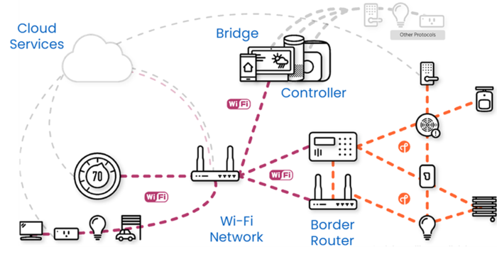
The following figure (from CSA) illustrates a general network topology and the different device types.
A Matter Fabric platform is composed of different equipment types:
- Matter end devices
- Matter bridge devices
- A simple controller
- A combined controller and border router
1.1. Matter end devices
The STM32-based end devices have been demonstrated with the following platforms:
- STM32 OpenThread Border Router (OTBR)
- Raspberry Pi (RPi)
- Google ecosystem
- Apple® ecosystem
- Samsung® ecosystem
- Amazon ecosystem
- Home Assistant
For the test and the demonstration, the STM32 Matter ED platform is programmed with one of the applications delivered in X-CUBE-MATTER:
- Lighting-App
- Window-App
- Generic-Switch-App
When the Generic-Switch-App is configured with low-power mode enabled, the UART trace functionality and the device display are disabled. To enable a more interactive demonstration of Matter functionality, disable the low-power mode as follows:
- For the STM32WB55MM-DK platform, set CFG_FULL_LOW_POWER to 0.
- For the STM32WBA65I-DK1 platform, set CFG_LPM_LEVEL and CFG_LPM_STDBY_SUPPORTED to 0.
For both platforms, these #define directives are located in the Applications\Matter\App\Core\Inc\app_conf.h file.
The operation mode for each ecosystem is presented in the following section.
For all ecosystems, the Matter network consists of the following elements:
- One STM32 Matter ED platform (for example, STM32WBA65I-DK1) as end device, programmed with the relevant firmware binaries.
- One STM32 OpenThread Border Router, Raspberry Pi, or commercial ecosystem hub.
- One smartphone with an ecosystem application or CHIPTool APK installed, or one Linux CHIPTool machine as a Matter commissioner and controller device. To obtain and rebuild the CHIPTool APK the user must follow the CSA guidelines. The Linux CHIPTool machine can be a Raspberry Pi with the TH image or a Linux machine (native or virtual) with Linux CHIPTool installed, both functioning as a commissioner and controller. The Linux CHIPTool installed in this demonstration section is the "Chip Tool Snap" from the Snap packaging. For instructions on installing this CHIPTool Snap and its usage for commissioning and control, refer to the Canonical chip-tool-snap GitHub. The Linux CHIPTool installed on a PC is typically used with the STM Border Router, which does not include CHIPTool.
- One Wi-Fi access point that provides network connectivity for the demonstration.
- One PC or laptop for programming or displaying the STM32 Matter ED platform logs. For terminal Tera Term configuration, refer to the Debug Logging section.
- One PC SSH-connected to the Raspberry Pi (or with a display and keyboard) for commands and logs during the demonstration using Raspberry Pi.
The following three figures illustrate the demonstration setups for a Thread-based STM32 Matter end-device platform:
- Using a smartphone as a commissioner and controller.
- Using a Linux PC with the installed CHIPTool as a commissioner and controller.
- Using a standalone Raspberry Pi (RPi) with the integrated CHIPTool as a commissioner and controller.
The following three figures show the demonstration setups for a Wi-Fi-based STM32 Matter end-device platform:
- Using a smartphone with CHIPTool APK as a commissioner and controller.
- Using a smartphone with ecosystem application as a commissioner and controller.
- Using a standalone Raspberry Pi (RPi) with the integrated CHIPTool as a commissioner and controller.
CHIPTool APK offers the following features:
- Scan the Matter QR code and display payload information to the user.
- Commission a Matter device.
- Send ON/OFF cluster commands to a Matter device with Lighting-App for CHIPTool APK, or any cluster request with other applications for Linux CHIPTool.
1.2. Matter bridge devices
The STM bridge devices have been demonstrated with the following platforms:
- Raspberry Pi (RPi)
- Google ecosystem
- Apple ecosystem
- Samsung ecosystem
- Amazon ecosystem
For an out-of-the-box demonstration, the STM32 Matter bridge platform (currently, only the NUCLEO-H753ZI board is supported) is programmed with the bridge application example (Bridge-App_debug.bin or Bridge-App_release.bin) delivered in X-CUBE-MATTER. This bridge application example is configured with six lights On/Off virtual (simulated) bridged devices.
The Matter network consists of the following elements:
- One STM32 Matter bridge platform: the NUCLEO-H753ZI board acts as the bridge device, simulates bridged devices, and is programmed with the bridge application binary.
- One Raspberry Pi or commercial ecosystem hub: operates as the Matter commissioner and controller device, and as the CHIPTool machine for demonstrations in the Raspberry Pi ecosystem.
- One smartphone: includes an ecosystem application for demonstrations in commercial ecosystems and functions as the Matter commissioner and controller device.
- One Wi-Fi access point: provides network connectivity for the demonstration.
- One PC or laptop: used for programming or displaying the STM32 Matter bridge platform logs. For terminal Tera Term configuration, see the Debug Logging section.
- One PC SSH-connected to the Raspberry Pi: alternatively, a display and a keyboard can be used for commands and logs during the demonstration with the Raspberry Pi.
The following two figures illustrate the demonstration setups for an STM32 Matter bridge platform:
- Using a smartphone as a commissioner and controller.
- Using a standalone Raspberry Pi (RPi) with the integrated CHIPTool as a commissioner and controller.
To start the bridge application demonstration:
- Open a terminal with Tera Term VT (or another logging terminal). For the Tera Term configuration refer to Debug Logging
- In the Tera Term window, open a connection to the COM port corresponding to the STM32 board
- The Matter STM32 bridge is ready to be paired to a Matter network (commissioning) when the following logs appear in the logging terminal
- The pairing parameters also logged in the logging terminal
- If commissioning is not performed within 15 minutes, the window is closed as illustrated in the following figure. To attempt a new commissioning reset the bridge device.
- Go to one of the following sections to continue the demonstration in the corresponding chosen ecosystem
2. STM ecosystem
The STM ecosystem is created with a STM32MP1+RCP as border router. An Android® smartphone with the CHIPTool APK or a Linux machine with Linux CHIPTool act as commissioner and controller. The border router and the CHIPTool APK device are connected to the same Wi-Fi access point. The Linux CHIPTool device is connected to the Wi-Fi access point or directly to the STM32MP1 via Ethernet.
For the OTBR setup, go to the dedicated wiki page STM32 OpenThread Border Router.
2.1. Demonstration of Thread-based devices
2.1.1. Demonstrating Lighting-App on STM32WB5MM-DK and STM32WBA65I-DK1 using CHIPTool APK
2.1.1.1. Commissioning
Once the complete setup is done, start the commissioning on the controller side as follows:
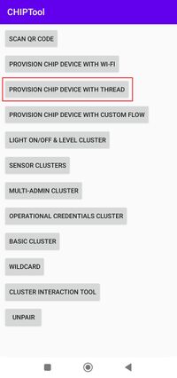
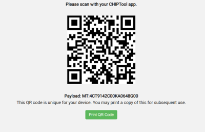
The commissioning is done in PROVISION CHIP DEVICE WITH THREAD, where the user scans the QR code generated by the end device, and displays the payload information. The controller must get the commissioning information from the Matter device. The data payload is encoded within a QR code, printed to the UART console by clicking on the following link from the UART log.
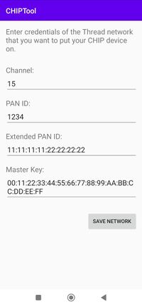
Once the QR code is scanned, the CHIPTool app displays the default Thread credentials needed to establish a Thread network between the end device and the border router. Those credentials must match with the active configuration on Thread border router side. ChipTool does not get dynamically Thread credentials from border router, it is up to the end user to ensure that Thread configuration sent to end device is consistent with one on Thread border router.
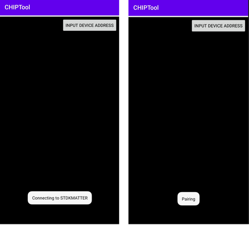
To initiate the commissioning over the Bluetooth® LE protocol, click on SAVE NETWORK and scan for discoverable Matter devices. Pair with the device and start the procedure.
On the end device side, the display screen shows that the device is connected over Bluetooth LE (BLE connected) before switching to the Thread network (Network Joined):
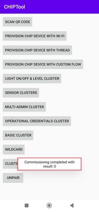
At the successful end of the commissioning, the STM32 Matter ED is connected to the Matter network and the Fabric is created. The result on both controller and end device sides is shown below:
- Controller side:
- End device side:
2.1.1.2. App demonstration
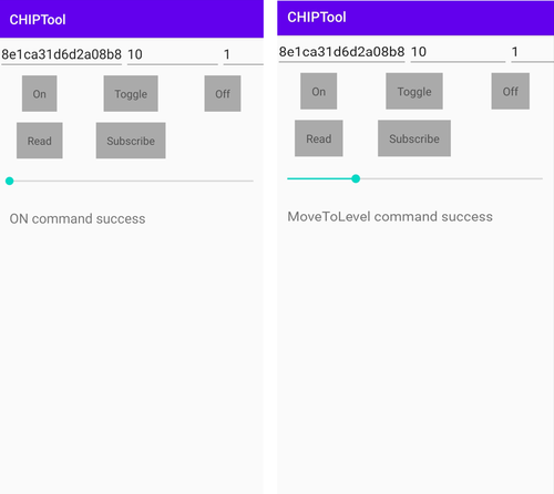
At this stage, it is possible to pilot the light of the end device directly using the controller (here the CHIPTool APK application) by sending ON/OFF commands and changing the light level using the LIGHT ON/OFF & LEVEL CLUSTER.
On the end device side, the received commands are displayed on the LCD screen, which shows the message LED ON when the ON command is pressed, and updates the light level when the level cluster is modified as follows:
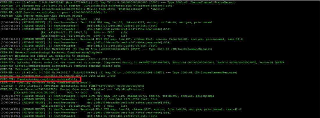
When the device is commissioned successfully, the following trace information is shown over the UART:
To properly start a new commissioning, it is mandatory to perform a factory reset, clear the CHIPTool cache, and restart the app. The factory reset is performed as follows, depending on the board type:
- On STM32WB55MM-DK: press the B1 button for at least 10 seconds.
- On STM32WBA65I-DK1: press Joystick SELECT for at least 5 seconds.
- On NUCLEO-U575ZI with X-NUCLEO-67W61M1: apply two short presses on the SW1 button of the mezzanine board NUCLEO-67W61M1.
2.1.2. Demonstrating Window-App on STM32WB5MM-DK and STM32WBA65I-DK1 using Linux CHIPTool
2.1.2.1. Commissioning
Run the following command to obtain the Thread network dataset
sudo ot-ctl dataset active -x
Then run the discovery and pairing command
sudo chip-tool pairing ble-thread <node_id> hex:<Thread network dataset> 20202021 <discriminator_id>
The default PIN code is 20202021, and the default discriminator id is 3840.
When the device successfully joins the Thread network during the commissioning procedure, this is indicated on the LCD screen, as illustrated by the following pictures.
The commissioning then continues on the Thread network. If it fails, the LCD screen displays "Fabric Failed". A successful commissioning completion is indicated on the LCD screen by the message "Fabric Created", and in the device logs with the message "commissioning completed successfully".
2.1.2.2. App demonstration
Commands results/effects can be observed on the device LCD.
- Open window cover
sudo chip-tool windowcovering up-or-open <node_id> <endpoint_id>
The display shows the OPEN level in percentage, from 5 to 95%, then "lift finish" (corresponding to 100%) at the end. This is illustrated by the following figure.
- Close window cover
sudo chip-tool windowcovering down-or-close <node_id> <endpoint_id>
The display shows the CLOSE level, in percentage, from 95 to 5%, then "lift finish" (corresponding to 0%) at the end. This is illustrated by the following figure.
- Lift window cover to a given position
sudo chip-tool windowcovering go-to-lift-percentage <percentage in units 0.01%> <node_id> <endpoint_id>
The display shows the OPEN or CLOSE level, in percentage, from the current (minus 5%) to the target (minus 5%) level given as parameter, then "Lift finish" (corresponding to the target position) at the end. The two following figures illustrate, respectively:
- a Lift OPEN to 50% with as initial position the window completely closed
- a Lift CLOSE to 25% with as initial position the window completely opened
The percentage parameter value is 5000 for 50%, and 2500 for 25%.
- Stop window cover motion
sudo chip-tool windowcovering stop-motion <node_id> <endpoint_id>
This command is launched while a Lift OPEN/CLOSE is ongoing. It results in stopping of the motion at the current OPEN/CLOSE level. The display then shows "Lift finish" just after the current percentage. The two following figures illustrate, respectively:
- a stop motion during a Lift OPEN, with as initial position the window completely closed
- a stop motion during a Lift CLOSE, with as initial position the window completely opened
2.1.3. Demonstrating Generic-Switch-App on STM32WB5MM-DK and STM32WBA65I-DK1 using Linux CHIPTool
Supported features are the momentary switch (short and long press) and the momentary switch release (short and long press release).
Multi-press feature is not supported.
When the delivered Generic-Switch-App application is configured with low-power mode enabled, you must disable it to activate the UART trace functionality and the device display. To do this, follow the instructions for disabling low-power mode in the Matter end devices subsection of the Overview section.
2.1.3.1. Commissioning
Run the following command to obtain the Thread network dataset:
sudo ot-ctl dataset active -x
Then run the discovery and pairing command:
sudo chip-tool pairing ble-thread <node_id> hex:<Thread network dataset> 20202021 <discriminator_id>
The default PIN code is 20202021, and the default discriminator id is 3840.
When the device joins the Thread network during the commissioning procedure, this is indicated on the LCD screen, as illustrated by the following pictures.
The commissioning then continues on the Thread network. If it fails, the LCD screen displays "Fabric Failed." A successful commissioning completion is indicated on the LCD by the message "Fabric Created", and in the device logs with the message "commissioning completed successfully".
2.1.3.2. App demonstration
Commands results/effects can be observed on the Raspberry Pi CHIPTool logs.
- Read current position attribute
sudo chip-tool switch read current-position <node_id> <endpoint_id>
The following pattern appears within the CHIPTool logs.
- Subscription to events
The button B2 on the STM32WB5MM-DK board or Joystick LEFT on the STM32WBA65I-DK1 board is used as the switch button. Event notifications are displayed in the CHIPTool logs. To enable this, activate the CHIPTool interactive mode by executing the following steps.
sudo chip-tool interactive start
For parameters <...> refer the CHIPTool help.
- - Subscription to short press event
sudo chip-tool switch subscribe-event initial-press <min-interval> <max-interval> <node_id> <endpoint_id>
When you press the B2 button on the STM32WB5MM-DK board or the Joystick LEFT on the STM32WBA65I-DK1 board, the following pattern appears in the CHIPTool logs.
- - Subscription to short release event
sudo chip-tool switch subscribe-event short-release <min-interval> <max-interval> <node_id> <endpoint_id>
When you apply a short press then release to the button B2 on the STM32WB5MM-DK board or Joystick LEFT on the STM32WBA65I-DK1 board, the following pattern appears within the CHIPTool logs.
- - Subscription to long press event
sudo chip-tool switch subscribe-event long-press <min-interval> <max-interval> <node_id> <endpoint_id>
When you apply a long press to the button B2 on the STM32WB5MM-DK board or Joystick LEFT on the STM32WBA65I-DK1 board, the following pattern appears within the CHIPTool logs.
3. Raspberry Pi ecosystem
The Raspberry Pi is primarily used for the Matter test harness but can also demonstrate Matter devices. This ecosystem is created with a Raspberry Pi as a controller and a border router and either an Android® smartphone with the CHIPTool APK or the Linux CHIPTool embedded in the test harness image as a commissioner and controller. For the Raspberry Pi setup, obtain a test harness Raspberry Pi bootable image, flash it to the Raspberry Pi following the CSA instructions in the Matter Test-Harness User Manual, and follow the guide to set up the OTBR. Once the OTBR is ready and the device is programmed with the chosen application, proceed to the demonstration using the CHIPTool APK for the lighting application or the Linux CHIPTool within the Raspberry Pi (standalone Raspberry Pi) for any application.
3.1. Demonstration of Thread-based devices
3.1.1. Demonstrating Lighting-App on STM32WB5MM-DK and STM32WBA65I-DK1 using CHIPTool APK
In this case the demonstration procedure is the same as for STM ecosystem, only difference being that the RPi is used as OTBR instead of STM32MP1+RCP.
3.1.2. Demonstrating Window-App on STM32WB5MM-DK and STM32WBA65I-DK1 using Linux CHIPTool
3.1.2.1. Commissioning
Follow the Matter Test-Harness User Manual for the device commissioning procedure.
The successfully joining of the Thread network during the commissioning procedure is indicated on the LCD screen as illustrated by the following picture.
The commissioning then continues on the Thread network, and if it fails this is indicated by a "Fabric Failed" message on the LCD screen. The successful commissioning completion can be observed on the device logs with the message "Commissioning completed successfully".
3.1.2.2. App demonstration
Commands results/effects can be observed on the device LCD.
- Open window cover
./chip-tool windowcovering up-or-open <node_id> <endpoint_id>
The display shows the OPEN level, in percentage, from 5 to 95%, then "Lift finish" (corresponding to 100%) at the end. This is illustrated by the following figure.
- Close window cover
./chip-tool windowcovering down-or-close <node_id> <endpoint_id>
The display shows the CLOSE level, in percentage, from 95% to 5%, then "Lift finish" (corresponding to 0%) at the end. This is illustrated by the following figure.
- Lift window cover to a given position
./chip-tool windowcovering go-to-lift-percentage <percentage in units 0.01%> <node_id> <endpoint_id>
The display shows the OPEN or CLOSE level, in percentage, from the current (minus 5%) to the target level given as parameter (minus 5%), then "Lift finish" (corresponding to the target position) at the end. The two following figures illustrate respectively:
- a Lift OPEN to 50% with as initial position the window completely closed
- a Lift CLOSE to 25% with as initial position the window completely opened--->
The percentage parameter value is 5000 for 50% and 2500 for 25%.
- Stop window cover motion
./chip-tool windowcovering stop-motion <node_id> <endpoint_id>
This command is launched while a Lift OPEN/CLOSE is ongoing and will result in stopping of the motion at the current OPEN/CLOSE level. The display then should show "Lift finish" just after the current percentage. The two following figures illustrate respectively:
- a stop motion during a Lift OPEN with as initial position the window completely closed
- a stop motion during a Lift CLOSE with as initial position the window completely opened
3.1.3. Demonstrating Generic-Switch-App on STM32WB5MM-DK and STM32WBA65I-DK1 using Linux CHIPTool
Supported features are the momentary switch (short and long press) and the momentary switch release (short and long press release).
Multi-press feature is not supported.
When the delivered Generic-Switch application is configured with low-power mode enabled, you must disable it to activate the UART trace functionality and the device display. To do this, follow the instructions for disabling low-power mode in the Matter end devices subsection of the Overview section.
3.1.3.1. Commissioning
Follow the Matter Test-Harness User Manual for the device commissioning procedure.
When the device successfully joins the Thread network during the commissioning procedure, this is indicated on the device LCD screen as illustrated by the following picture.
The commissioning then continues on the Thread network, and if it fails this is indicated by a "fabric failed" message on the device's LCD screen. The successful commissioning completion can be observed on the device logs with the message "Commissioning completed successfully".
3.1.3.2. App demonstration
Commands results/effects can be observed on the Raspberry Pi CHIPTool logs.
- Read current position attribute
./chip-tool switch read current-position <node_id> <endpoint_id>
The following pattern appears within the CHIPTool logs.
- Subscription to events
The button B2 on the STM32WB5MM-DK board or Joystick LEFT on the STM32WBA65I-DK1 board is used as the switch button. Event notifications can be observed on the CHIPTool logs. For that, you need to activate the CHIPTool interactive mode by executing the following.
./chip-tool interactive start
For parameters <...> refer the chip-tool help.
- - Subscription to short press event
switch subscribe-event initial-press <min-interval> <max-interval> <node_id> <endpoint_id>
When you apply a short press to the button B2 on the STM32WB5MM-DK board or Joystick LEFT on the STM32WBA65I-DK1 board, the following pattern appears within the CHIPTool logs.
- - Subscription to short release event
switch subscribe-event short-release <min-interval> <max-interval> <node_id> <endpoint_id>
When you apply a short press then release to the button B2 on the STM32WB5MM-DK board or Joystick LEFT on the STM32WBA65I-DK1 board, the following pattern appears within the CHIPTool logs.
- - Subscription to long press event
switch subscribe-event long-press <min-interval> <max-interval> <node_id> <endpoint_id>
When you apply a long press to the button B2 on the STM32WB5MM-DK board or Joystick LEFT on the STM32WBA65I-DK1 board, the following pattern appears within the CHIPTool logs.
- - Subscription to long release event
switch subscribe-event long-release <min-interval> <max-interval> <node_id> <endpoint_id>
When you apply a long press then release to the button B2 on the STM32WB5MM-DK board or Joystick LEFT on the STM32WBA65I-DK1 board, the following pattern appears within the CHIPTool logs.
3.2. Demonstration of Wi-Fi-based devices
3.2.1. Demonstrating Lighting-App on NUCLEO-U575ZI-Q and X-NUCLEO-67W61M1 using Linux CHIPTool
This section is dedicated to the STM32 Wi-Fi-based Matter platform NUCLEO-U575ZI-Q and X-NUCLEO-67W61M1.
3.2.1.1. Commissioning
Start the commissioning using the following pairing command
./chip-tool pairing ble-wifi <node_id> <Wi-Fi network SSID> <Wi-Fi network password> <pin_code> <descriminator>
The node_id is any number that uniquely identify the device in the Matter network, the pin_code is a password with a default value of 20202021, and the discriminator with a default value of 3840 allows to differentiate devices having the same product and vendor ID.
For example, with a node_id equal to 1, the default pin_code and the default descriminator, the pairing command is the following:
./chip-tool pairing ble-wifi 1 <Wi-Fi network SSID> <Wi-Fi network password> 20202021 3840
Replace <Wi-Fi network SSID> and <Wi-Fi network password> by actual values for the Wi-Fi access point of your setup. The successful commissioning completion can be observed on the logging terminal with the message "Commissioning completed successfully".
3.2.1.2. App demonstration
CHIPTool commands are used to control ON/OFF Light devices, and the command result can be observed on the logging terminal and/or the CHIPTool logs. The results of commands that cause a change in the light state can also be observed on the NUCLEO-U575ZI-Q board's led LD2.
- Light on while current state is OFF
./chip-tool onoff on <node_id> <endpoint_id>
- Light off while current state is ON
./chip-tool onoff off <node_id> <endpoint_id>
- Light toggle
./chip-tool onoff toggle <node_id> <endpoint_id>
In case of a successful command 'onoff on', 'onoff off' or 'on/off toggle', the following patterns (for respectively 'off to on' and 'on to off') appear on the logging terminal:
- Light on/off status
./chip-tool onoff read on-off <node_id> <endpoint_id>
In case of a successful command 'onoff read on-off', the following pattern appears within the CHIPTool logs:
- - 'OnOff: FALSE' if the status is OFF
- - 'OnOff: TRUE' if the status is ON
3.3. Demonstration of Ethernet-based devices
3.3.1. Demonstrating Bridge-App using Linux CHIPTool
3.3.1.1. Commissioning
On the Tera Term log, you can check the instance name of your device
On the Linux CHIPTool PC you can check the commissionable status of the bridge device using the following command
./chip-tool discover commissionables
The instance name of your bridge device is visible in the command result (CHIPTool log).
Start the commissioning using the following pairing command
./chip-tool pairing onnetwork <node_id> <pin_code>
The node_id is any number that uniquely identifies the bridge node in the Matter network, and the pin_code is a password with a default value of 20202021.
For example, with a node_id equal to 1 and the default pin_code, the pairing command is the following:
./chip-tool pairing onnetwork 1 20202021
The successful commissioning completion can be observed on the logging terminal with the message "Commissioning complete".
3.3.1.2. App demonstration
The bridge is configured to have a maximum of 8 devices, but the delivered example contains 6 pre-initialized virtual (simulated) bridged Lights On/Off devices (Light1 to Light6).
The identifiers of the endpoints attached to these devices are written at the beginning of the log:
Note: As you can observe from the above figure, endpoints for bridged devices take values from 3 to 8. The reason is that value 0 is dedicated to the root node endpoint, and values 1 to n (n = 2 in the current use case) are for aggregators endpoints. Endpoints 3 to 8 correspond to devices Light1 to Light6.
CHIPTool commands are used to control ON/OFF Light devices, and the command result can be observed on logging terminal and/or CHIPTool logs.
- Light on while current state is OFF
./chip-tool onoff on <node_id> <endpoint_id>
- Light off while current state is ON
./chip-tool onoff off <node_id> <endpoint_id>
- Light toggle
./chip-tool onoff toggle <node_id> <endpoint_id>
In case of a successful command 'onoff on', 'onoff off' or 'on/off toggle', the following patterns (for respectively 'off to on' and 'on to off') appear on the logging terminal:
- Light on/off status
./chip-tool onoff read on-off <node_id> <endpoint_id>
In case of a successful command 'onoff read on-off', the following pattern appear within the CHIPTool logs:
- - 'OnOff: FALSE' if the status is OFF
- - 'OnOff: TRUE' if the status is ON
Command Line Interface (CLI) commands from the terminal can be used for several purposes.
With focus on the terminal, press the key 'Enter' and CLI commands help is displayed as shown in the following figure.
4. Commercial ecosystems
The STM32 Matter device platforms are demonstrated with the ecosystems of selected major Matter players, including Apple, Amazon, Google, and Samsung.
The STM32 Matter device platform, whether as an end-device platform or a bridge platform, operates like any other Matter device using the provided QR code.
- QR code for STM32 Matter end-device platform
- QR code for STM32 Matter bridge platform
To connect the STM32 Matter device to those ecosystems and perform a demonstration, follow the guide provided for each ecosystem.
For ST device types (applications provided in X-CUBE-MATTER) interoperability with the different ecosystems, refer to the "Matter Device Type Platform Compatibility Matrix" from CSA.
For the demonstration setup, refer to the Overview section
4.1. Apple ecosystem
The demonstration setup for the Apple ecosystem includes an Apple HomePod Mini (with iOS 16.1 or later) serving as a controller and border router, an Apple iPhone® (with iOS 16.1 or later) running the Apple Home application or any application supporting the Matter smart home standard, acting as a commissioner and controller, and the STM32 Matter device to be demonstrated. For guidelines on how to proceed with the demonstration, refer to the following link.
4.2. Amazon ecosystem
The demonstration setup for the Amazon ecosystem includes an Amazon Echo Hub as a controller and border router, an Alexa® application as the commissioner and controller on an Android® or iOS device, and the STM32 Matter device to be demonstrated. For guidelines on how to proceed with the demonstration, refer to the following link.
During the commissioning phase, Alexa, acting as the controller, instructs the device to discover the surrounding Thread networks. The available list of Thread networks is sent to Alexa and displayed on the phone screen. The user is then invited to select one. If the selected network is recognized by Alexa, the commissioning continues, otherwise Alexa requests the network key.
Note that Alexa verifies the serial number during the device commissioning. Therefore, when multiple STM32 Matter device kits are used in a demonstration, it is necessary to modify the serial number, as described in Serial number modification, to differentiate the different kits.
4.3. Google ecosystem
The demonstration setup for the Google ecosystem includes a Google Nest Hub™ as a controller and border router, a Google Home™ application (GHA) as a commissioner and controller on an Android® or iOS device, and the STM32 Matter device to be demonstrated. For guidelines on how to proceed with the demonstration, refer to the following link.
4.4. Samsung ecosystem
The demonstration setup for the Samsung ecosystem includes a SmartThings® Station as a controller and border router, an Android® device with the SmartThings® application or an iOS device running iOS 16.2 or later with the SmartThings® application version 1.6.94 or later as a commissioner and controller , and the STM32 Matter device to be demonstrated. For guidelines on how to proceed with the demonstration, refer to the following link.
4.5. Home Assistant ecosystem
The demonstration setup for the Home Assistant ecosystem includes the following components:
- A Home Assistant Green configured as a controller and border router.
- A PC connected to the Home Assistant Green for Matter integration.
- An Android® or iOS phone with the Home Assistant application installed.
- A SkyConnect/Connect ZBT-1 dongle configured as an OpenThread border router for Matter-over-Thread devices.
- The STM32 Matter device to be demonstrated.
Our demonstration also integrated simultaneous and multiple Matter (Wi-Fi and Thread) devices and Zigbee devices, with a second SkyConnect dongle configured as a Zigbee adapter. For guidelines on how to proceed with the demonstration, refer to the following link.
5. Multi-fabric
For a multi-fabric demonstration, select the first fabric and commission the device in this fabric. Then, follow the guide provided by the related ecosystem to commission the device in other commercial ecosystems.
