For the sake of brevity, we refer to Realistic Use Cases (RUC) as an abbreviation throughout this discussion.
1. Introduction
This page describes how to quickly handle an On/Off Light Device with On/Off Light Switch.
The project generates a Zigbee Light Device acting as a Router (ZR) and Zigbee Light Switches as End Devices (ED).
It serves as a good introduction for a first approach to a ST Zigbee mesh solution.
2. Functioning
This example demonstrates STM32WB application capabilities using the Zigbee network with ST devices to connect switches and light bulbs in different scenarios.
Starting from a basic example where one switch is connected to one light bulb, it is possible to connect multiple switches to the same light bulb, or to connect one switch to multiple light bulbs, along with other combinations, to test the ST Zigbee functionalities.
| RUC Lighting |
|---|
3. Getting started
This project implements an ST Zigbee mesh supporting the Coordinator (ZC), Router (ZR) and End Device (ZED) features.
These features are sufficient to set up a first Zigbee network [1].
The ZED are not Sleepy devices, but it is a possible extension. For more information, see Application Note [2].
3.1. Hardware requirements
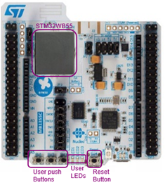
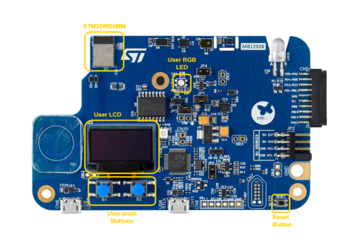
P-NUCLEO-WB55[3] and STM32WB5MM-DK[4] are required to set up the demonstration.
For more information, visit STM32WB Development ecosystem.
| P-NUCLEO-WB55 | STM32WB5MM-DK |
|---|---|
3.2. Software and system requirements
All the application projects can be found on Github hotspot:
- Zigbee_Coord
- Zigbee_Light_Switch
- Zigbee_Occupancy_Sensor
- Zigbee_OnOff_Sensor
- Zigbee_OnOff_Light
For more information to build Zigbee application, visit STM32WB Build Zigbee Project.
To check messages from the board, use any convenient terminal software through the UART Interface, see Wiki: Zigbee Log via UART for more information.
3.3. Install the Zigbee network
To install the RUC example, follow the HowTo Join a Zigbee Network and HowTo bind devices.
4. Zigbee implementation
This example uses the Zigbee cluster On/Off [5] with the following topology:
- a Gateway as ZC
- Light switches as ZED with client cluster on P-NUCLEO-WB55 [3]
- Light bulb as ZR with server cluster on a STM32WB5MM-DK [4]
So, the main topology uses 1 ZC, 2 ZR and 4 ZED, both ZR bound to 2 ZED each.
It is possible to extend devices with Zigbee clusters Level control [6], Color control[7], etc. to add device features.
A crucial point to note is that the server holds the attribute values, that is, the state of the light in this case. If the client wants to know the light's state, it needs to send the command "read the attribute" to the server. When two devices are bound together, they can set up a link where the server sends the state of some attributes when they are modified. These attributes are called reportable. For instance, in a network with 2 switches and one light, if both switches are bound to the light, Switch 1 can turn the light on, and Switch 2 is informed of the change in the light's state.
4.1. Light switch
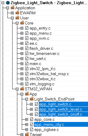
The client command (switch) sends a message (On/Off/Toggle) to the server (light bulb). The implementation is straightforward and high-level, allowing you to choose the messages delivery method: broadcast, group or unicast. In this example, the message is sent in unicast mode, which requires binding the devices together. This approach enables configuring the reporting process and receiving an acknowledgement from the server.
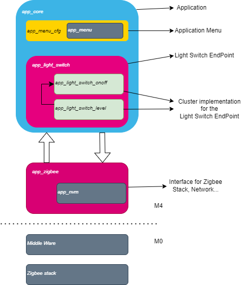
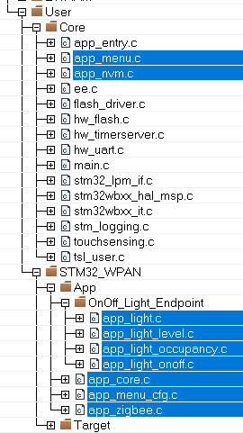
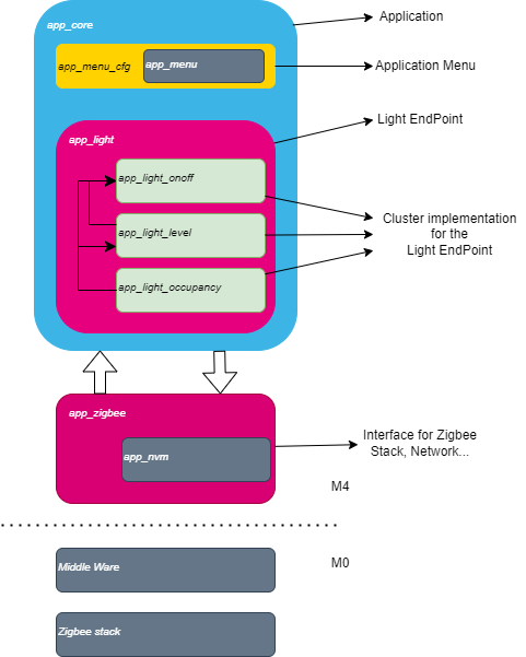
Find below the code example of the use case and the different layer to understand and modify it.
| Source code | SW Layers |
4.2. Light bulb
After reception of a command from a client, an appropriate callback function is executed by the server.
If there is an attribute modification, the server sends this modification to each client according to the report configuration in the local binding table.
Find below the code example of the use case and the different layer to understand and modify it.
| Source code | SW Layers |
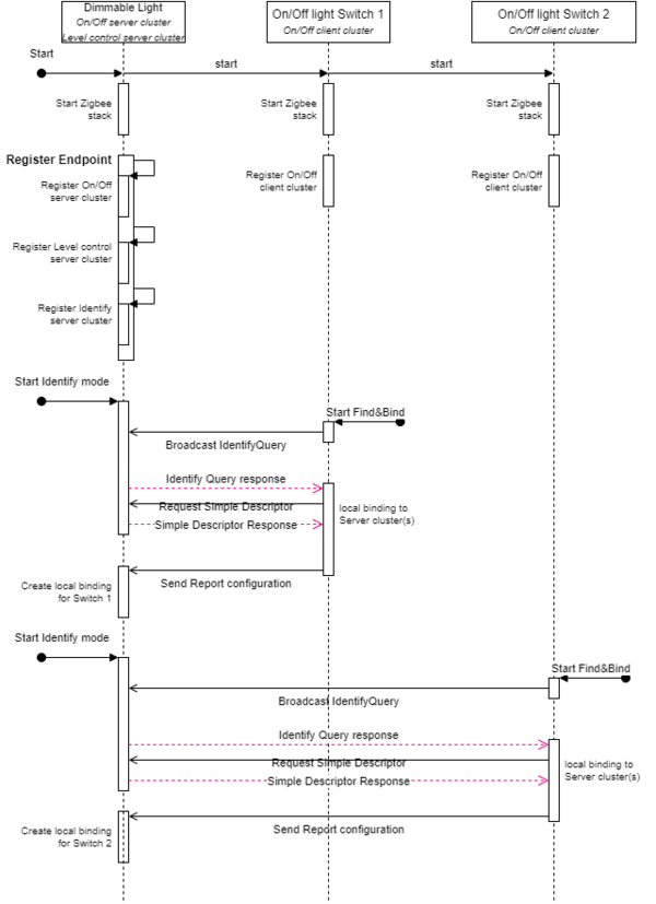
4.3. Binding and report process
To manage many configurations, attribute reports are used to troubleshoot issues.
So, each time a client binds to a server, a configuration report is created to notify the client of the attribute modification.
For more information, see Wiki: Zigbee Binding.
Find below the Binding process used in this example.
| Binding process |
|---|
|
|
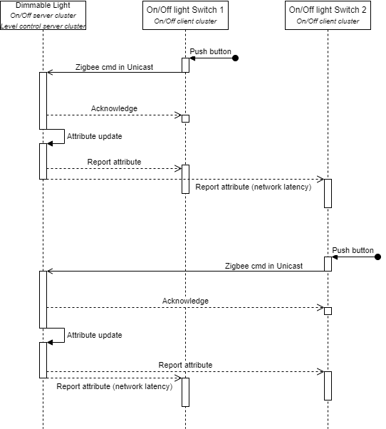
In the case of multiple clients, the Report attribute is used to maintain a coherence between each client when the state of the light is changed on the server.
Find below the Report attribute process for two clients:
| Report attribute process |
|---|
4.4. Retry process
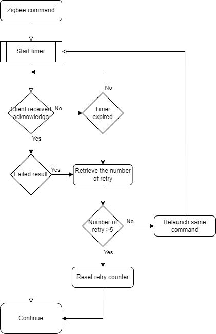
When a client sends a command, there are three possible situations:
- Nominal case: Everything works fine, and the client receives successful acknowledgement from the server.
- Error case 1: The client receives an acknowledgement from the server, but with failure that implies an error in processing the command.
- Error case 2: The client does not receive any response from server, indicating a communication issue.
To make it more reliable, a “retry” process was created when a Zigbee command from client fails.
As explained before, for all applications, all the commands are sent in unicast. Once the command is sent, the server responds with an acknowledgement. If this one includes a failure message, the message is resent to the server.
Find below the retry process and the flow chart implemented in source code:
| Retry process |
|---|
| Flow chart |
By implementing this mechanism, the number of failed commands significantly decreases.
5. Possible extension
From this use case, some extensions are possible:
- Add several Light Bulbs (multi-server) to observe when clients send commands and server behavior.
- Add dimmable light and switch.
- Add color control light and switch.
- Add PIR occupancy sensor to light on/off automatically.
Below, the example shows an extension with a PIR sensor and dimmable switch:
| RUC Lighting extension |
|---|
6. Tests and results
To stress the system and verify its proper functioning, a series of tests has been conducted.
| Test | Passed/Failed |
|---|---|
| Adding a server (ZR) and getting current service value | Passed |
| Adding a client (ZED) and getting current service value | Passed |
| Detecting and handling the case of report not received | Passed |
| Correcting the issue of report not received by reading service value | Passed |
| Same Zigbee cmd from multiple clients at the same time | Passed |
| Different Zigbee cmd from multiple clients at the same time | Passed |
| Overloading the system with sending Zigbee cmd on time (with PIR) | Passed |
| Latency test | Passed |
| Distance (3-hops) | Passed |
| Endurance time (7 days) | Passed |
| Remove Coordinator | Passed |
7. Acronyms and definitions
| Term | Definition |
|---|---|
| ZC | Zigbee Coordinator |
| ZR | Zigbee Router |
| ZED | Zigbee End Device |
| RUC | Realistic Use Case |
| PIR | Passive Infra-Red sensor, motion detectors |
8. References

