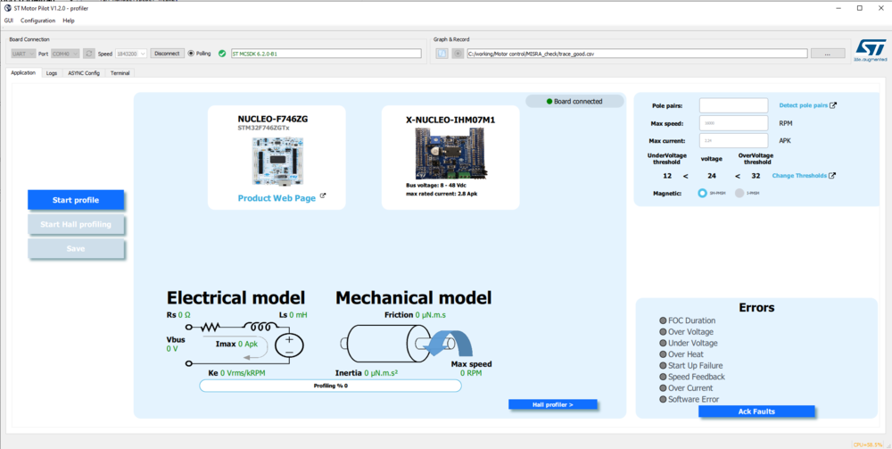
From X_CUBE_MCSDK version 6.1 the Motor Profiler tools is included inside the Motor Pilot tool.
1. Motor profiler
The Motor profiler software is now integrated to the Motor Pilot as a QML file. It allows the user to:
- Do a basic profiling.
- Do a profiling with the Hall sensors.
- Do an offset resistance detection.
- Be able to see and change the voltage threshold.
- Detect the number of pole pairs with guided detection.
1.1. How to generate profiler project
In a way to ease the user to profile a motor, the new MCSDK6.2.0 provides an updated efficient manner to generate a Motor profiler software binary to answer this requirement.
The new MCSDK WB tool is able to generate a Motor profiler project based on the described boards and the FOC motor control software. In consequence, there is no more need to store and update all possible or new Motor profiler binaries that depend on a hardware board setup and different MCU topologies.
The Motor profiler algorithm is provided into the MCSDK firmware as a library linkable and compliable with ARMv7 and ARMv8 architecture. Any kind of IDEs or Arm compilers can be used to generate this Motor profiler binary. Depending on the IDEs (type of Arm compilers that is, arm cc, gcc...), the Motor profiler algorithm is embedded into two different libraries. The following table describes these different versions of libraries.
| IDE Compiler | Arm V7 Motor Profiler Lib | Arm V8 Motor Profiler Lib |
|---|---|---|
| IAR, Stm32Cube | libmp-IAR_ARMv7-M.a | libmp-IAR_ARMv8-M.a |
| Keil | libmp-MDK-ARM_ARMv7-M.a | libmp-MDK-ARM_ARMv8-M.a |
The MCSDK WB tools contain .json board description files. For some power and inverter boards, a resistorOffset parameter is embedded, useful for determining the resistor rs, one of the electrical parameters of the motor. As soon as one of these kinds of board is described and use for motor profiling, this parameter must be present into its corresponding .json file. If a Motor profiler firmware is generated without the resistorOffset parameter described into the power or inverter board selected, a default value equal to -32768 of this parameter is found into the resulting generated Motor profiler firmware. In consequence, the motor profiling will not be allowed by the Motor profiler tool. The Motor profiler tool then provides the ability to compute this missing resistorOffset parameter.
The Motor profiler tool is a subset of the Motor Pilot tool, and it shares the same interface. This proven and efficient tool allows to connect a control or inverter board, and execute the profiling of a motor by computing electrical and mechanical parameters of a motor.
Some of the motor control algorithms are using a Hall sensor to detect the position and speed of the motor. With a Hall sensor, the positioning of the rotor is obtained by reading the digital signals coming from the Hall sensors (that is, connected to three timer channel inputs). Thanks to the Motor profiler tool and the Motor profiler firmware loaded into a control or inverter board, any Hall sensor can be profiled generating two specific parameters useful for Hall processing.
1.1.1. Profiler firmware generation
A described board configuration means that the power or inverter board is present into the MCSDK WB data base (MC_SDK_6.2.0\Utilities\PC_Software\STMCWB\assets\hardware\board), as a .json file, and the reistorOffset parameter is embedded into this board description file. As it is done for any kind of FOC project, the MCSDK6.2.0 WB version allows the user to generate a Motor profiler project by following the following steps:
Create a new motor control FOC algorithm configuration project with any kind of motor, a described power and a control board, or a described inverter board. The following table contains the list of described power and inverter boards supported by this MCSDK WB version to generate a Motor profiler project.
| Inverter | Power Board | Power Board | Power Board | Power Board | Inverter | Power Board | Power Board | Power Board | Power Board | Power Board | Power Board |
|---|---|---|---|---|---|---|---|---|---|---|---|
| EVSPIN32G4 | X-NUCLEO-IHM07M1 | X-NUCLEO-IHM16M1 | X-NUCLEO-IHM17M1 | X-NUCLEO-IHM17M1 | B-G431B-ESC1 | STEVAL-IHM023V3 | STEVAL-IPM05F | STEVAL-IPM10B | STEVAL-IPM15B | STEVAL-IPMN3GQ | STEVAL-IPMNM1N |
This list may be updated as soon as STMicroelectronics designs new efficient boards to support improvement in motor control algorithm and new STM32 ICs in each new MCSDK release.
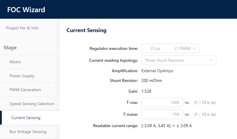
When the project is created, first check the "current sensing" configuration and specially set a "Three shunt resistors" for "Current reading topology".
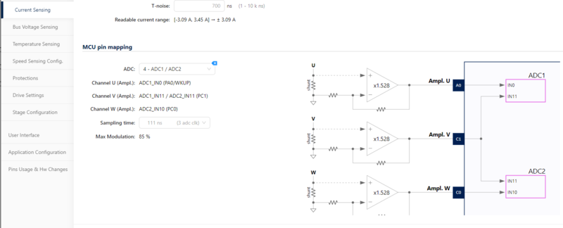
As most of the projects are using a "3 shunts / 2 ADC current sensing" topology (except iNUCLEO-H563ZI), please set up this configuration into the "ADC" line.
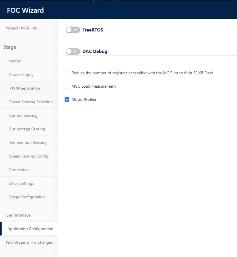
To configure this created FOC project in a motor profiling way, please tick the "Motor profiler" feature into the "Application configuration" stage.
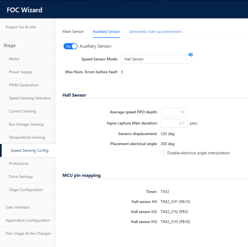
To profile a Hall sensor, the user must configure the Motor profiler project of the MCSDK WB with the speed auxiliary sensor mode set to Hall sensor.
The Motor profiler firmware can then be generated, compiled, and downloaded into the flash as explained in the previous chapter. As soon as the Motor profiler tool is connected to the control or inverter board, the Hall sensor profiling window is accessible by pushing the button Hall profiler button. Note that the Start Hall profiling will be accessible only if a profiling of the motor has been executed previously. If it is not the case, please first launch a motor profiling and then profile the Hall sensor.
Now, you can save and generate the Motor profiler project for the wished IDE tool chain (that is, STM32CubeIDE) proposed by the MCSDK WB.
As soon as the Motor profiler project has been generated, a compilation of this project must be performed thanks to the selected IDE or any Arm compilation script.
The binary generated is now ready to be loaded into the flash of the control or inverter board with the selected IDE tool or using that is, the STM32CubeProgrammer tool.
When the Motor profiler firmware runs into the MCU, the Motor profiler tool can be used by launching the Motor Pilot tool on MCSDK 6.2.0.
1.2. How to use profiler
1.2.1. Board connection
Like for the Motor Pilot, check the Board connection part, and connect the Motor profiler tool to the control or inverter board. A Motor profiler GUI is now accessible for the user.
As soon as the Board is connected, all pieces of information are displayed, and the Motor profiler tool is now able to communicate with an embedded firmware to profile the motor.
1.2.2. Profiler parameter
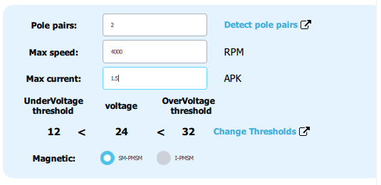
Configure the required know information of the motor: Pole pairs, max speed and max current information, and voltage thresholds. Besides, the internal permanent magnet synchronous motors (IPMSM) with its Ld/Lq ratio, or the surface permanent magnet synchronous motors (SM-PMSM) can be selected.
1.2.3. pole pairs detection
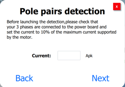
Pole pair detection is a new feature that comes with this profiler and does not require a power generator to detect the pole pair number. To use this feature, click the Detect pole pairs button, which opens a new window.
To start detection, click Next.
In this window, enter the value of the current to be injected to make the motor strong enough to be able to turn it manually afterwards. The value entered must be close to 15% of the maximum current that the motor can support. Otherwise, the motor may overheat.
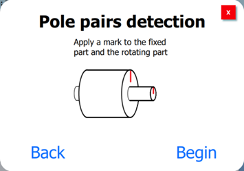
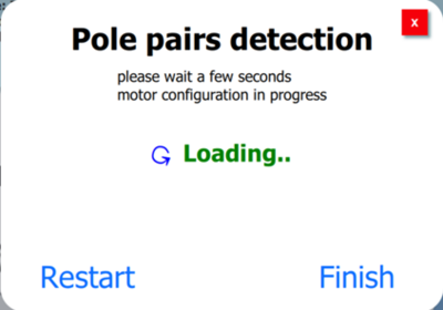
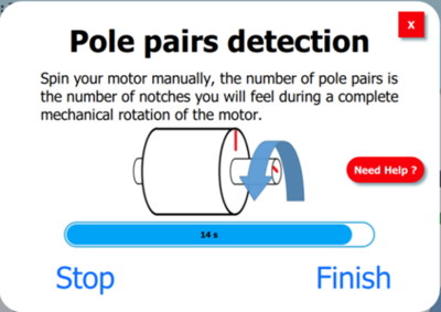
Please apply a mark on the fixed part of the motor and the rotating part, then you can turn the rotating part and count the number of Pole Pair. The firmware then prepares the motor by applying a current ramp of the value entered in the previous step.
You have 15 seconds to make a complete rotation of the rotating part of the motor and must count the number of notches. This number is the number of pole pairs. Then, click Finish.
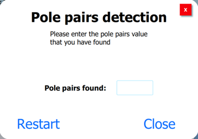
Finally, you can enter the number of Pole Pairs found, then close the window and start the Motor profiling.
1.2.4. Start profiling
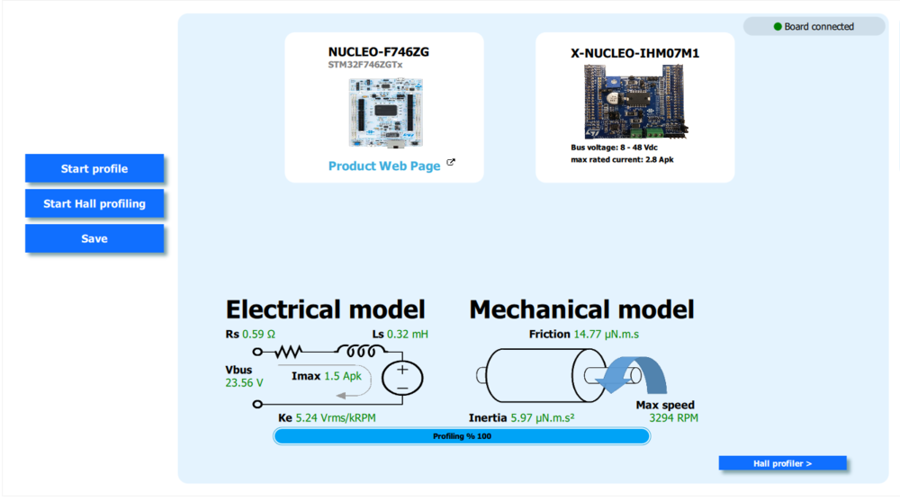
Finally, it is time to press the "start profile" button. The motor profiling sequence starts, and the electrical and mechanical model parameters are successively computed during the execution of the profiling represented by the progress of the bar increment. As soon as the profiling is finished, all these parameters are updated and displayed. To end the process, an option is proposed to save all these motor parameters into a .json file.
1.2.5. Start Hall sensor profiling
Note that the Start Hall profiling is accessible only if a profiling of the motor has been executed previously. If it is not the case, first launch a motor profiling and then profile the Hall sensor.
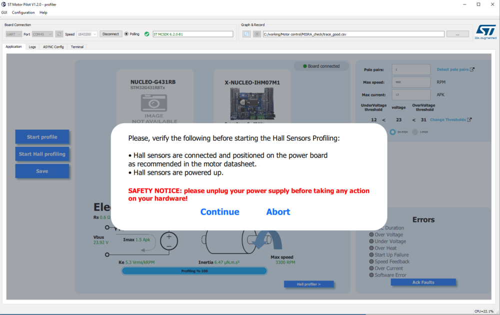
Click on the Start Hall profiling to start the process. The Motor profiler tool asks the user at the beginning of the process to check the connections and the power supply required for a Hall sensor profiling.
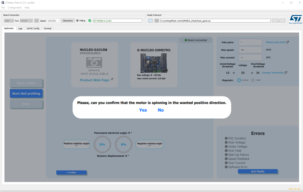
Then, the Motor profiler tool also asks the user to verify that the motor is spinning into a positive direction. If it is not the case, recheck your Hall sensor connection and power supply, and reexecute the Hall sensor profiling.
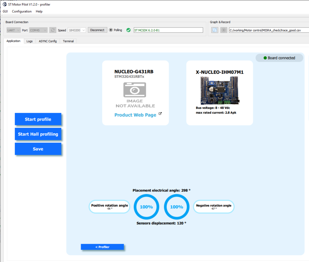
The Hall sensor profiling is done in both directions. As soon as the two rotation directions processes are finished, the two computed values of the parameters are displayed.
1.2.6. Profiling results
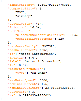
All parameters generated thanks to the motor and Hall sensor profiler can be stored into an MCSDK WB motor .json database that is, C:\Users\frqxxxxx.st_workbench\hardware\motor. When you have saved your file, you can load your motor on the workbench. Here is an example of the generated .json:
