Sensing is a major part of smart objects and equipment, for example, condition monitoring for predictive maintenance. It enables context awareness and production performance improvement. It also results in a drastic decrease in downtime due to preventive maintenance.
The FP-AI-MONITOR1 function pack for the STM32Cube is a multisensor AI data monitoring framework on the wireless industrial node.
For more information about how to use FP-AI-MONITOR1 look at the FP-AI-MONITOR1 user manual.
The rest of the article discusses some of the key technologies and concepts behind the function pack v2.0.0. It also guides the reader through the source code of the embedded software.
1. Introduction
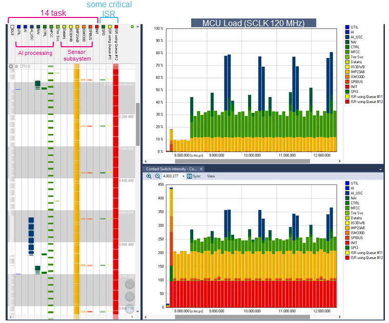
The firmware in FP-AI-MONITOR1 implements a complex multitasking embedded application that takes full advantage of STM32 power. The following image gives an idea of the complexity managed by the firmware. The left side of the image displays 14 tasks (each task is an independent execution flow) running in parallel, together with several interrupt service routines (ISR), in STM32L4R9ZI single-core microcontroller.
At the same time, we can see in the right part of the image that, despite the high number of context switches, the average load percentage of the MCU core, with a clock frequency set to 120MHz, is below 50%. These results are made possible with an application framework optimized for STM32, and a set of firmware components designed on top of the framework.
1.1. Who must read this document?
This document is intended for firmware developers who develop or support the development of AI applications on the edge. Users of this document must know little of the following:
- Real-time operating system (RTOS). FreeRTOSTM is part of the kernel of FP-AI-MONITOR1.
- Principle of object-oriented programming (like inheritance, polymorphism, virtual function).[1][2][3]
- Unified modeling language (UML®)
Note: FreeRTOS is a trademark of Amazon in the United States and/or other countries. All other trademarks are the property of their respective owners.
1.2. Main components of the firmware
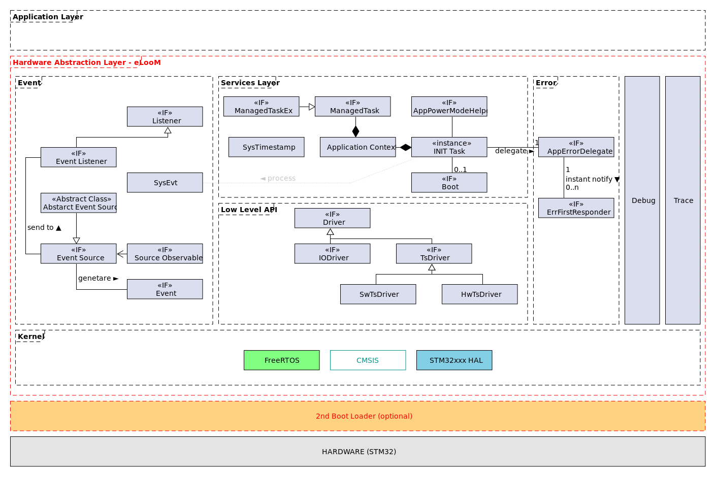
We can look at the complex architecture of FP-AI-MONITOR1 from different perspectives: from the high-level view presented in the user manual, up to the more detailed diagram that we can find, in the developer documentation available in FP-AI-MONITOR1 local installation folder at this location:
FP_MONITOR1_V2.0.0\Documentation
The next sections look at the main components of the firmware. They are:
- eLooM: the application framework.
- Sensor Manager: an eLooM component to configure and get raw data from the sensors on the board.
- Digital processing unit (DPU): an eLooM component to process data.
On top of the above main components the application implements a set of AI-related processing tasks:
- AI_USC_Task_t
- AITask_t
- MfccTask_t
- NeaiTask_t
2. eLooM application framework (main concepts)
eLooM stands for embedded Light object-oriented fraMework for STM32. It is an application framework designed for STM32, and specifically for soft real-time, event driven, multitasking, and low-power embedded applications. It has been optimized over several years.
2.1. The managed task abstraction
The framework introduces the concept of Managed Task, which is an RTOS native task extended with new features. These new features are the result of analysis and generalization of problems common to STM32 applications, which leads us to a generic solution with an optimized trade-off between memory footprint and performance. The class diagram for the managed task is displayed in the following image:
If we think of a managed task as an OO class, then it implements a set of methods used by the framework to coordinate the task activities at runtime, like:
- System initialization: At startup, the system initializes all hardware resources as well as the software ones used by the managed tasks.
- Power management: The system coordinates the managed tasks to switch from one state to the other of a Power Mode State Machine (PM state machine, or simply state machine)[4] defined by the application.
- Error management: The system handles the errors reported by a managed task or its subcomponents, and it checks that all managed tasks are working fine.
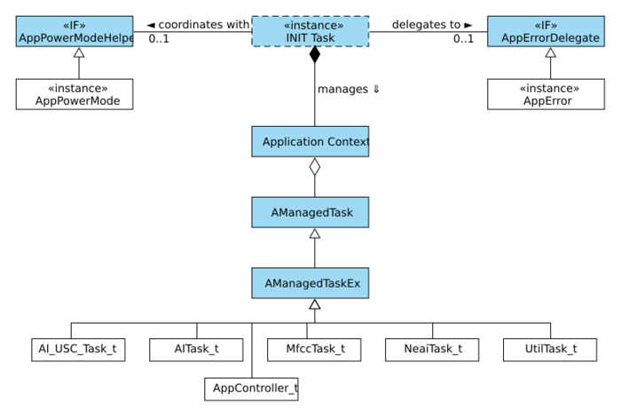
Not all the methods are implemented by the AManagedTask or its subclass AManagedtTaskEx. Indeed, in the above image, the methods displayed in italic inside the Virtual methods block are pure virtual functions. Note that the prefix 'A' in front of the class name (AManagedTask) stands for abstract. This means that we cannot instantiate an object of the class (because it would be an incomplete object), but a developer can subclass one of the managed task classes and he must provide an application-specific implementation of the pure virtual functions. This is what happens in FP-AI-MONITOR1. The following image shows the application-specific classes that we provide with the function pack as white rectangles, while the sky-blue ones are provided by the framework.
By extending one of the base classes provided by the framework and implementing the pure virtual functions, the application tasks are well integrated, and the application code is split from the base code provided by ST.
2.1.1. AI_USC_Task, a concrete example
Let us look at one of the managed tasks created for the function pack, the AI ultrasound classification task (AI_USC_Task_t). As a general recommendation, the implementation is split into three files, two header files, and one source file:
- AI_USC_Task.h: the main header file declares the type for the new managed task and its public API.
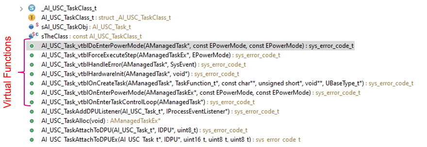
- AI_USC_Task_vtbl.h: the header file containing only all the virtual functions implemented by the managed task. Declaring all virtual functions in a separate file is a practical choice to understand at a glance which behaviors are redefined by the class. It is not a mandatory rule. Another way is to search the Outline view of the IDE for all function names that contain _vtbl (that stands for virtual table) as shown in the below image.
- AI_USC_Task.c: the source file defines the managed task. This file contains the implementation of the public as well as the private methods of the managed task.
How does a user-defined managed task extend the AManagedTask or the AManagedTaskEx base classes provided by the framework? The technique used is the inheritance by composition[5] because it is easy to implement in C.
/* file: AI_USC_Task.h */

/**
 * Create a type name for _AI_USC_Task_t.
 */
typedef struct _AI_USC_Task_t AI_USC_Task_t;

/**
 * AI_USC_Task_t internal structure.
 */
struct _AI_USC_Task_t
{
  /**
   * Base class object.
   */
  AManagedTaskEx super;

  /* Class-specific members must be declared here */

  /**
   * Task input message queue. The task receives messages of struct AIMessage_t type in this queue.
   * This is one of the ways that the task exposes its services at the application level.
   */
  QueueHandle_t in_queue;

  /* Task variables must be added here. */

  /**
   * Digital processing unit specialized in the CubeAI library.
   */
  AiUSC_DPU_t dpu;

  /**
   * Data buffer used by the DPU but allocated by the task. The size of the buffer depends
   * on many parameters like:
   * - the type of the data used as input by the DPU
   * - the length of the signal
   * - the number of signals to manage circularly to decouple the data producer and the data process.
   * The correct size in bytes is computed by the DPU with the method AiUSC_DPUSetStreamsParam().
   */
  void *p_dpu_buff;
};
The first member in the AI_USC_Task_t structure is a variable of the base class - AManagedTaskEx super - . Thanks to the way AManagedTask is defined, it is possible to use a pointer of AI_USC_Task_t* type with all the functions that require a parameter of AManagedTask* or AManagedTaskEx* type. For example:
AI_USC_Task_t my_task;
ACAddTask(pAppContext, (AManagedTask*)&my_task);
In the above example, we use the explicit cast of the pointer to avoid compiler warnings.
There is one more thing to do: we need to use the virtual functions defined by the AI_USC_Task_t class to override those defined in the base class. This is done during the allocation of an instance of the class, as highlighted in the following snippet:
/* file: AI_USC_Task.c */

/**
 * The only instance of the task object.
 */
static AI_USC_Task_t sTaskObj;

AManagedTaskEx *AI_USC_TaskAlloc(void)
{
  /* In this application there is only one instance of the task,
   * so that this allocator implements the singleton design pattern.
   */

  /* Initialize the super class */
  AMTInitEx(&sTaskObj.super);

  sTaskObj.super.vptr = &sTheClass.vtbl;

  return (AManagedTaskEx*)&sTaskObj;
}
This allocator implements the singleton design pattern by using the static variable sTaskObj, and effectively avoids the problem of dynamic allocation.
The virtual pointer - sTaskObj.super.vptr - points to a table, named the virtual table, containing all the pointers to the virtual functions in the correct order, as defined by the base class:
/* file: AManagedTaskEx_vtbl.h */

/**
 * Create type name for _AManagedTask_vtb.
 */
typedef struct _AManagedTaskEx_vtbl AManagedTaskEx_vtbl;

struct _AManagedTaskEx_vtbl {
  sys_error_code_t (*HardwareInit)(AManagedTask *_this, void *pParams);
  sys_error_code_t (*OnCreateTask)(AManagedTask *_this, TaskFunction_t *pvTaskCode, const char **pcName, unsigned short *pnStackDepth, void **pParams, UBaseType_t *pxPriority);
  sys_error_code_t (*DoEnterPowerMode)(AManagedTask *_this, const EPowerMode eActivePowerMode, const EPowerMode eNewPowerMode);
  sys_error_code_t (*HandleError)(AManagedTask *_this, SysEvent xError);
  sys_error_code_t (*OnEnterTaskControlLoop)(AManagedTask *_this);
  sys_error_code_t (*ForceExecuteStep)(AManagedTaskEx *_this, EPowerMode eActivePowerMode);
  sys_error_code_t (*OnEnterPowerMode)(AManagedTaskEx *_this, const EPowerMode eActivePowerMode, const EPowerMode eNewPowerMode);
};
For the AI_USC_Task_t, the virtual table is defined in the structure AI_USC_TaskClass_t, and in its initialization code, highlighted in the following snippet, we can see how the virtual functions of the AI_USC_Task_t class are linked with the base class:
/* file: AI_USC_Task.c */

/**
 * Class object declaration. The class object encapsulates members that are shared between
 * all instances of the class.
 */
typedef struct _AI_USC_TaskClass_t {
  /**
   * AI_USC_Task class virtual table.
   */
  AManagedTaskEx_vtbl vtbl;

  /**
   * AI_USC_Task class (PM_STATE, ExecuteStepFunc) map. The map is implemented with an array and
   * The key is the index. The number of items of this array must be equal to the number of PM states
   * of the application. If the managed task does nothing in a PM state, then set to NULL the
   * relative entry in the map.
   */
  pExecuteStepFunc_t p_pm_state2func_map[];
} AI_USC_TaskClass_t;
};

/**
 * The class object initialization.
 */
static const AI_USC_TaskClass_t sTheClass = {
    /* Class virtual table */
    {
        AI_USC_Task_vtblHardwareInit,
        AI_USC_Task_vtblOnCreateTask,
        AI_USC_Task_vtblDoEnterPowerMode,
        AI_USC_Task_vtblHandleError,
        AI_USC_Task_vtblOnEnterTaskControlLoop,
        AI_USC_Task_vtblForceExecuteStep,
        AI_USC_Task_vtblOnEnterPowerMode
    },

    /* class (PM_STATE, ExecuteStepFunc) map */
    {
        AI_USC_TaskExecuteStepState1,
        NULL,
        NULL,
        NULL,
        AI_USC_TaskExecuteStepAIActive,
        NULL,
        AI_USC_TaskExecuteStepAIActive
    }
};
At this point, the AI_USC_Task behaves as a managed task.
There is another question to be answered: how the framework knows about the managed tasks created by the application?
2.2. Application entry points
In a typical bare-metal application with a procedural programming model, a developer starts coding inside the main() function that is the initial entry point. This is not the case for an eLooM-based application where the main.c file is very simple like this:
/* file main.c */

#include <stdio.h>
#include "services/sysinit.h"
#include "task.h"


/* The main function initializes a minimum set of hardware resources and creates the INIT task, before giving the control to the scheduler.
 * The main application entry points are defined in the App.c file.
 */

int main()
{
  // System initialization.
  SysInit(FALSE);

  vTaskStartScheduler();

  while (1);
}
Before giving the control to the RTOS - vTaskStartScheduler() -, the SysInit(FALSE) initializes the minimum set of hardware resources and creates the INIT task that is the first and only task running during the system initialization process.
Normally the main.c file does not need to be modified. eLooM, instead, defines four entry points as weak functions as reported in the following table.
| Call order | Function prototype | Note |
|---|---|---|
| 1 | IApplicationErrorDelegate *SysGetErrorDelegate(void) | Optional. This function is used by the system during the application startup to get an application-specific object that implements the IApplicationErrorDelegate interface. |
| 2 | IAppPowerModeHelper *SysGetPowerModeHelper(void) | Mandatory. This function is used by the system during the application startup to get an application-specific object that implements the IAppPowerModeHelper interface. |
| 3 | sys_error_code_t SysLoadApplicationContext(ApplicationContext *pAppContext) | Mandatory. Add all managed tasks to the application context. |
| 4 | sys_error_code_t SysOnStartApplication(ApplicationContext *pAppContext) | Optional. This function is called by the framework at the end of the initialization process and before the INIT task releases the control to the application tasks. |
A developer must provide at least the SysGetPowerModeHelper() and the SysLoadApplicationContext() functions. They can be defined in an application file. For example, FP-AI-MONITOR1 uses the file FP_MONITOR1_V2.0.0\Projects\STM32L4R9ZI-STWIN\Applications\FP-AI-MONITOR1\Src\App.c for this purpose.
Let us look at the SysLoadApplicationContext() function defined in the function pack.
/* file: App.c */

sys_error_code_t SysLoadApplicationContext(ApplicationContext *pAppContext)
{
  assert_param(pAppContext);
  sys_error_code_t xRes = SYS_NO_ERROR_CODE;

  // Allocate the task objects
  spSPIBusObj = SPIBusTaskAlloc(&MX_SPI3InitParams);
  spIMP23ABSUObj = IMP23ABSUTaskAlloc(&MX_DFSDMCH0F1InitParams, &MX_ADC1InitParams);
  spISM330DHCXObj = ISM330DHCXTaskAlloc();
  spIIS3DWBObj = IIS3DWBTaskAlloc();
  spUtilObj = UtilTaskAlloc(&MX_TIM5InitParams, &MX_TIM16InitParams, &MX_GPIO_PF6InitParams);
  spNeaiObj = NeaiTaskAlloc();
  spAIObj = AITaskAlloc();
  spAI_USC_Obj = AI_USC_TaskAlloc();
  spMfccObj = MfccTaskAlloc();
  spControllerObj = AppControllerAlloc();
  DataInjectorTaskAllocStatic(&sDataInjObj);

  // Add the task object to the context.
  xRes = ACAddTask(pAppContext, (AManagedTask*)spSPIBusObj);
  xRes = ACAddTask(pAppContext, (AManagedTask*)spIMP23ABSUObj);
  xRes = ACAddTask(pAppContext, (AManagedTask*)spISM330DHCXObj);
  xRes = ACAddTask(pAppContext, (AManagedTask*)spIIS3DWBObj);
  xRes = ACAddTask(pAppContext, (AManagedTask*)spUtilObj);
  xRes = ACAddTask(pAppContext, (AManagedTask*)spNeaiObj);
  xRes = ACAddTask(pAppContext, (AManagedTask*)spAIObj);
  xRes = ACAddTask(pAppContext, (AManagedTask*)spAI_USC_Obj);
  xRes = ACAddTask(pAppContext, (AManagedTask*)spMfccObj);
  xRes = ACAddTask(pAppContext, (AManagedTask*)spControllerObj);
  xRes = ACAddTask(pAppContext, (AManagedTask*)&sDataInjObj);

  return xRes;
}
In the beginning, all the managed task objects are allocated. The allocation strategy is an important topic for an embedded application, but it is not covered in this article. Nevertheless, let us note that we prefer to use, whenever it is possible, static allocation, and the singleton design pattern when it makes sense for the specific class.
Once a managed task object is allocated, we tell the framework that this task is part of the application by using the ACAddTask() function provided by the Application Context API declared in the ApplicationContext.h file, for example:
xRes = ACAddTask(pAppContext, (AManagedTask*)spNeaiObj);
If a managed task is not added to the application context, then it is not initialized, its resources are not allocated, the native RTOS task is not created, and so on. It does not exist during the application execution.
In the above example, the six tasks highlighted in yellow are the specific ones created for this function pack, the other tasks are provided by the Sensor Manager component, and we introduce them in the next section.
The rest of the system initialization is done by the framework, thanks to the INIT task that coordinates all managed tasks added to the application context as described in the section eLooM framework > System initialization of the developer documentation [6] of the function pack.
The other mandatory entry point is the SysGetPowerModeHelper(). This code snippet shows the implementation of FP-AI-MONITOR1:
IAppPowerModeHelper *SysGetPowerModeHelper(void)
{
// File: App.c

  // Install the application power mode helper.
  static IAppPowerModeHelper *s_pxPowerModeHelper = NULL;
  if (s_pxPowerModeHelper == NULL) {
    s_pxPowerModeHelper = AppPowerModeHelperAlloc();
  }

  return s_pxPowerModeHelper;
}
It instantiates an application object that implements the IPowerModeHelper interface. This interface is the key point to implement the application specific Power Mode State Machine as described in the "eLoom framework > Power Management" section of the developer documentation [6] of the function pack.
2.3. Managed tasks and system initialization
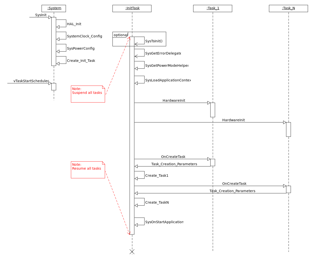
Until now, we analyzed the concept of Managed Task, how to create and integrate it within an embedded application, and what are the eLooM entry points. For an example of how these concepts are used at runtime, we can give a quick look at one specific moment of the application life-cycle: the system initialization.
The above sequence diagram displays the full initialization sequence since the call to the SysInit() function. With a look from top to bottom at the InitTask instance, we can recognize the framework entry points and when they are called:
- SysGetErrorDelegate()
- SysGetPowerModeHelper()
- SysLoadApplicationContext()
- SysOnStartApplication()
It is interesting to note that the application code is called when the RTOS is already running. So, for a developer, it is safe to assume that his code is executed always in a homogeneous multitasking environment. By comparison with other approaches, a developer must write code to be executed before the RTOS is running and he can use a subset of the API, while another application code is executed after.
Keep going in the InitTask timeline so that we see how it can manage the application managed tasks, thanks to the virtual functions:
- HardwareInit()
- OnCreateTask()
For more information about the system initialization refers to the developer documentation [6] of the function pack.
3. Sensor Manager: main concepts
Sensor Manager is an eLooM-based application-level module that interfaces sensors and offers their data to other application modules. It is implemented as an acquisition engine that:
- Orchestrates multiple managed tasks accesses to sensor bus data as follows:
- One or more sensors for each managed task
- Read/write requests via a queue to handle concurrency on common buses (a physicals bus is represented as a resource controlled by a managed task acting as gate keeper)
- Defines interfaces to avoid implementation dependencies
- Dispatches events to notify when data is ready
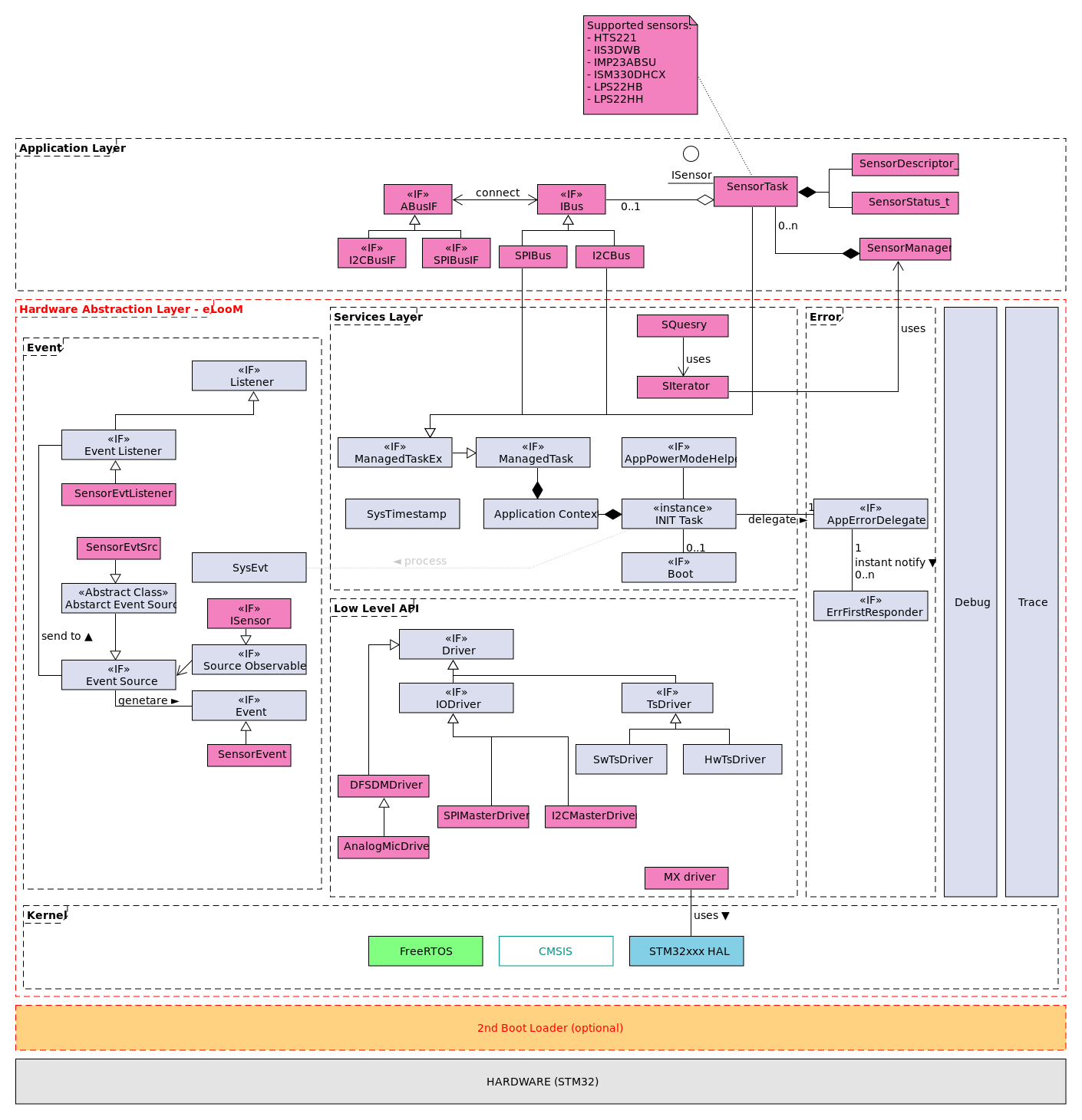
The following image is a high-level class diagram showing how the Sensor Manager (pink boxes) extends the framework.
The current implementation of the Sensor Manager supports these sensors:
- HTS221
- IIS3DWB
- IMP23ABSU
- ISM330DHCX
- LPS22HB
- LPS22HH
More sensors are going to be supported with further releases of the eLooM component.
You find more information about the Sensor Manager in the section Sensor Manager of the developer documentation [6] of the function pack.
3.1. Simple and advanced API exposed by the Sensor Manager
The first thing that we need to understand is how to interact with a sensor supported by the Sensor Manager. We saw that sensors and buses are modeled as subclasses of AManagedTaskEx. It means that working with a sensor is a two steps process:
- To add the sensor to the Application Context, so that the framework knows about it, and it initializes the sensor subsystem.
- To interact with the sensor using the proper API.
A sensor task is added to the Application Context during the system initialization as each other managed tasks, as we saw in the code snippet of the SysLoadApplicationContext() function. If the physical sensor is connected to a bus, then we need to do the same in the application code. This is normally done after all the objects have been initialized, in the SysOnStartApplication() entry point like in the FP code.
/* file: App.c */

sys_error_code_t SysOnStartApplication(ApplicationContext *pAppContext) {
  UNUSED(pAppContext);

  /* Remap the state machine of the Sensor Manager tasks */
  SensorManagerStateMachineRemap(spAppPMState2SMPMStateMap);

  /* Disable the automatic low-power mode timer */
  UtilTaskSetAutoLowPowerModePeriod((UtilTask_t*)spUtilObj, 0);

  /* Connect the sensors tasks to the SPI bus. */
  SPIBusTaskConnectDevice((SPIBusTask*)spSPIBusObj,
                          ISM330DHCXTaskGetSensorIF((ISM330DHCXTask*)spISM330DHCXObj));
  SPIBusTaskConnectDevice((SPIBusTask*)spSPIBusObj, IIS3DWBTaskGetSensorIF((IIS3DWBTask*)spIIS3DWBObj));

  /* Set the output queue for the USB CDC device. It is used to deliver all the incoming input */
  CDC_SetOutQueue(AppControllerGetInQueue((AppController_t*)spControllerObj));

  /* Connect the UtilTask with the AppController task to propagate the push button event. */
  UtilTaskSetCtrlInQueue((UtilTask_t*)spUtilObj, AppControllerGetInQueue((AppController_t*)spControllerObj));
  /* register AI processing with the application controller. */
  QueueHandle_t queueAi = AITaskGetInQueue((AITask_t*)spAIObj);
  QueueHandle_t queueMfcc = MfccTaskGetInQueue((MfccTask_t*)spMfccObj);
  QueueHandle_t queueUsc = AI_USC_TaskGetInQueue((AI_USC_Task_t*)spAI_USC_Obj);
  QueueHandle_t queueNeai = NeaiTaskGetInQueue((NeaiTask_t*)spNeaiObj);
  QueueHandle_t queueUtil = UtilTaskGetInQueue((UtilTask_t*)spUtilObj);
  AppControllerSetAIProcessesInQueue((AppController_t*)spControllerObj, queueAi, queueMfcc, queueUsc,queueNeai,queueUtil);

  /* set Mfcc DPU to controller */
  IDPU * p_dpu = MfccTaskGetDpu((MfccTask_t*)spMfccObj);
  AppControllerSetPreprocessDPU((AppController_t*)spControllerObj, p_dpu);

  /* Set the memory storage area for the data injector task */
  DataInjectorTaskSetMemStorageLocation(&sDataInjObj, GET_AI_DATA_STORAGE_ADDR(), AI_DATA_STORAGE_SIZE);

  return SYS_NO_ERROR_CODE;
}
For the second step, the Sensor Manager provides a different set of APIs targeting a simple use of the sensor or a more advanced one. The simple way to operate a sensor is to use the API exported by the Sensor Manager class.
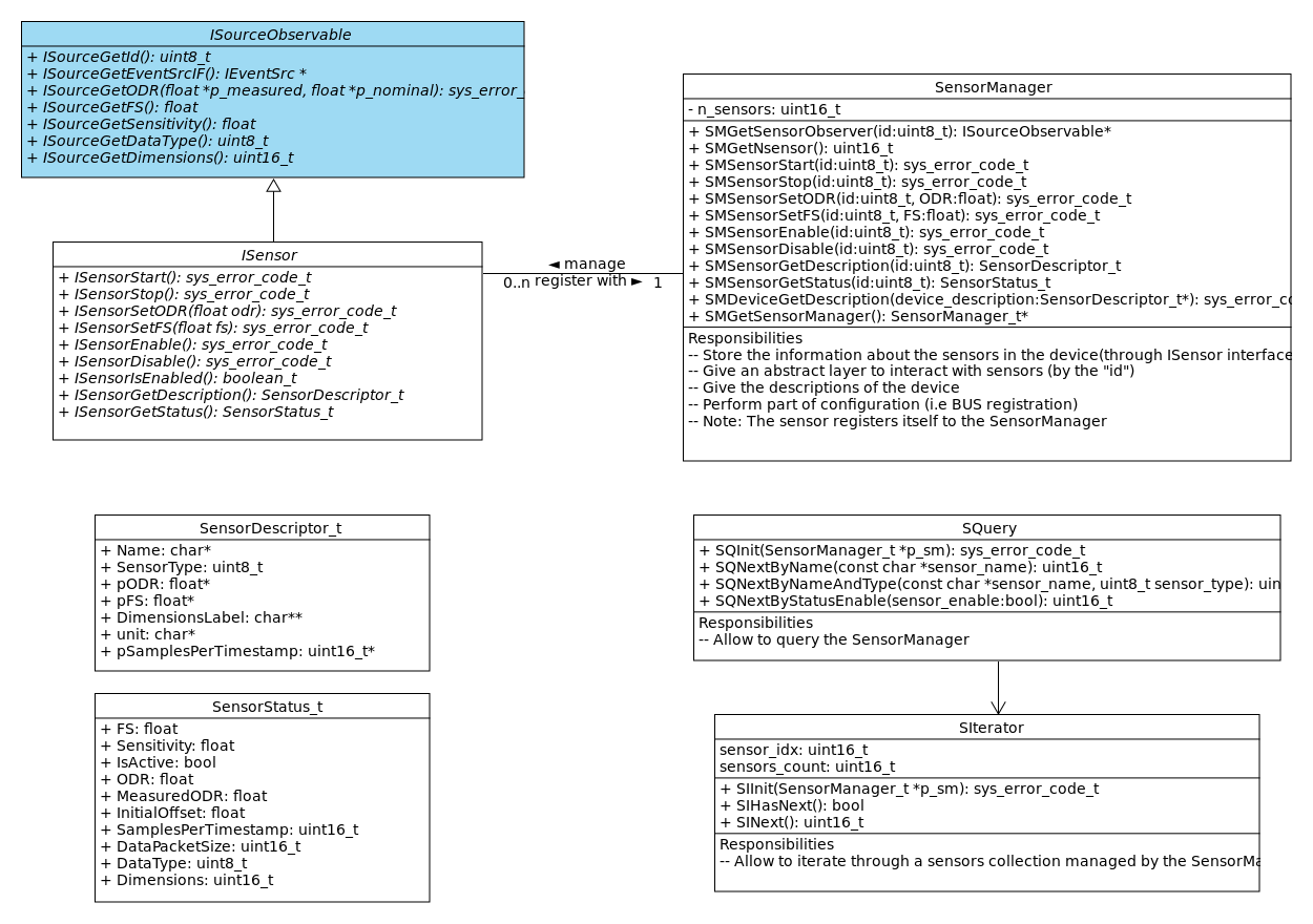
Given the ID of a sensor, it is possible to set its basic parameters like ODR, full scale, and so on. To get the actual value of the sensor 's parameter, we can use the SMGetSensorObserver() function to get the ISourceObservable interface of the sensor. This interface has been designed to provide a uniform and immutable interface between all sensors, and to abstract the concept of physicals sensor. Through this interface, all sensors are exposed to the system as generic data sources with a set of common properties. Note also that the ISourceObservable interface does not belong to the Sensor Manager component, but it is defined inside the application framework, eLooM. In this way, we can decouple the Sensor Manager from other components like, for example, the DPU that uses data produced by the sensors. All Sensor Manager APIs are based on the idea that a sensor has an ID. To know the ID of a sensor, it is possible to use the SIterator or the SQuery services provided by the Sensor Manager. The SIterator is used to iterate through the sensor collection managed by the Sensor Manager. The SQuery is used to search for sensors that match a given query. This is an example:
/* using a SIterator object. */
SIterator_t iterator;
SIInit(&iterator, SMGetSensorManager());
while(SIHasNext(&iterator))
{
   uint16_t sensor_id = SINext(&iterator);
   // do something with the sensor
   ISourceObservable *p_sensor_observer = SMGetSensorObserver(sensor_id);
   float odr = ISourceGetODR(p_sensor_observer);
   SMSensorSetODR(sensor_id, odr+1000);
}

/* using a SQuery object. */
SQuery_t query;
SQInit(&query, SMGetSensorManager());
sensor_id = SQNextByNameAndType(&query, "ism330dhcx", COM_TYPE_ACC);
if (sensor_id != SI_NULL_SENSOR_ID)
{
  SMSensorEnable(sensor_id);
  SMSensorSetODR(sensor_id, 1666);
  SMSensorSetFS(sensor_id, 4.0);
}
Of course, the Sensor Manager allows an advanced use of the sensor. It is possible to subclass a sensor class to access all the sensor internal data and also the low-level PID, but this is out of the scope of this tutorial.
3.2. Sensors used in FP-AI-MONITOR1
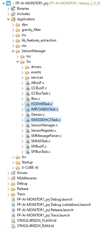
The current implementation of the Sensor Manager supports six sensors. Only three sensors are used by FP-AI-MONITOR1:
- IIS3DWB
- IMP23ABSU
- ISM330DHCX
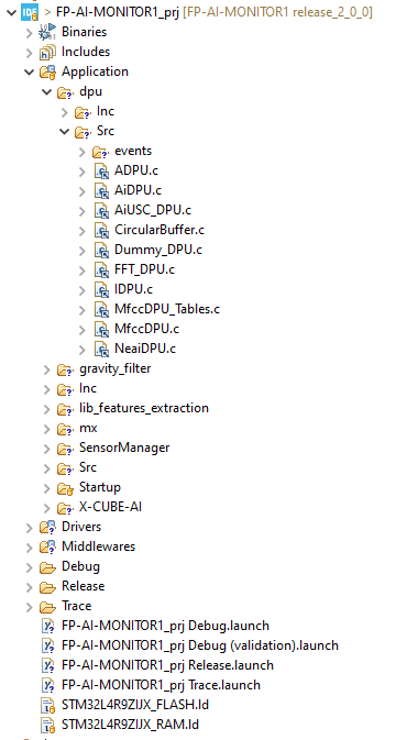
In fact, in the project three there are only the managed tasks for the used sensor, as displayed in the following image:
It shows how easy it is to use a sensor supported by the Sensor Manager, thanks to the modularity of an eLooM-based component. To use other sensors, we need only to link the relative files (two header files and one source file) to the project.
4. DPU: main concepts
Digital Processing Unit (DPU) is an eLooM-based application-level module that provides:
- A set of processing objects ready to use to process data coming from a data source (like the sensors of the Sensor Manager).
- An abstract class and a set of interfaces to simplify the creation of a new DPU.
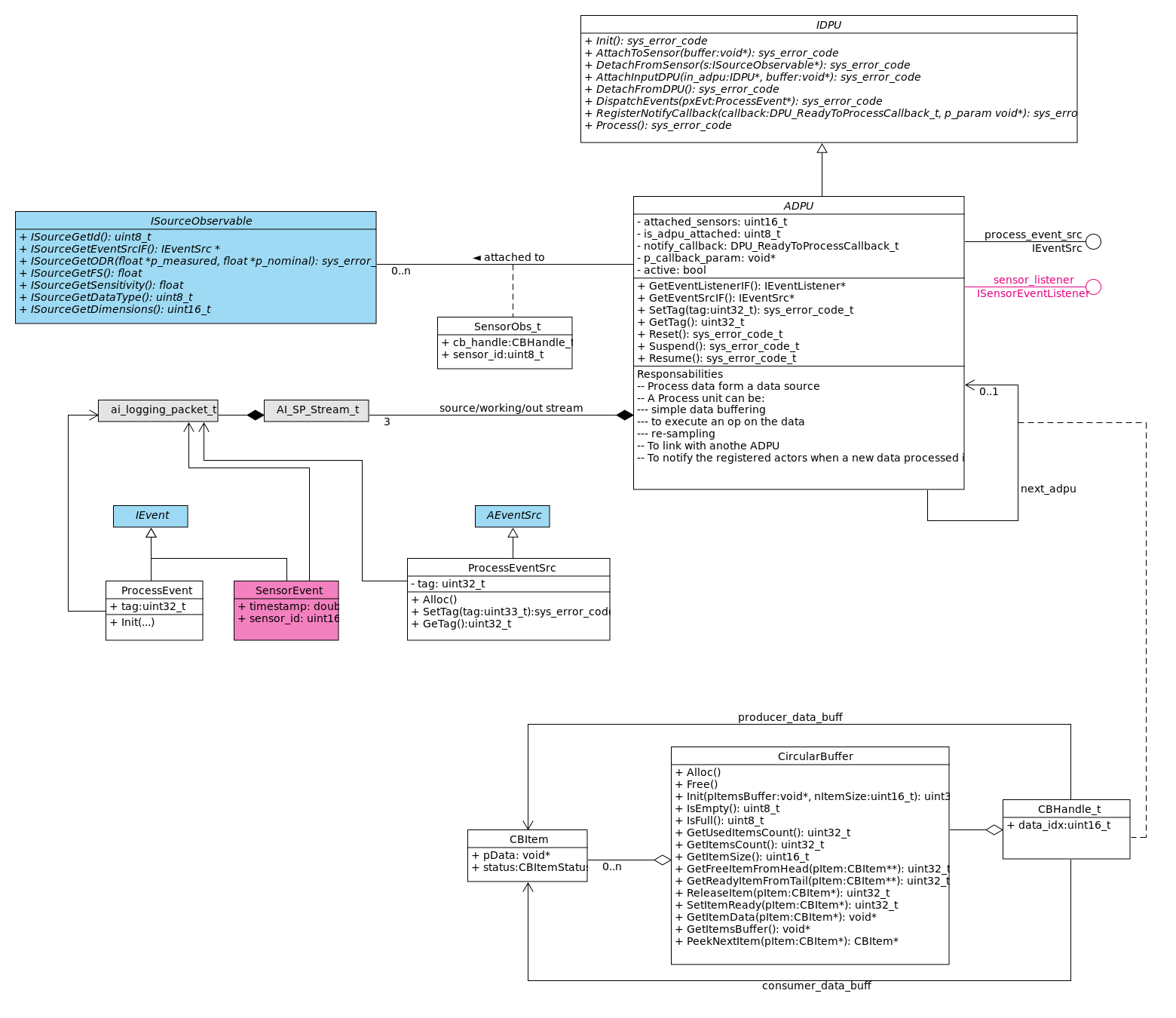
The above image shows the class diagram of the DPU engine. Starting from the definition of a generic DPU interface (IDPU), it provides an abstract class (ADPU) that implements the basic behavior of a DPU. The ADPU class is then used as a base class to implement the concrete DPU used in the function pack.
4.1. DPU programming model
DPUs are software objects that can do a few things:
- To connect to one or more data sources, like a sensor.
- To transform the input data into output data by applying specific processing.
- To dispatch the output data to all registered listeners.
- To connect to one other DPU to form a processing chain.
4.1.1. Connect a DPU to a data source
To attach an input data source to a DPU we use the API sys_error_code_t IDPU_AttachToSensor(IDPU *_this, ISourceObservable *s, void *buffer). The parameter buffer is an optional input parameter used to pass to the DPU a memory buffer allocated by the application. This buffer is used by the DPU to store the data coming from the data source, as well as to take advantage of the multitasking system. In fact, in a typical scenario, DPU stores the data coming from a data producer task (like a sensor), while, at the same time, it processes the data ready in a dedicated processing task as shown in the following image.
Let us look at a concrete example from FP-AI-MONITOR1: how the NeaiTask (that is a processing task) connects the NeaiDPU to a sensor.
// file NeaiTask.c

sys_error_code_t NeaiTaskAttachToSensorEx(NeaiTask_t *_this, ISourceObservable *p_sensor, uint16_t signal_size, uint8_t axes, uint8_t cb_items)
{
  assert_param(_this != NULL);
  sys_error_code_t res = SYS_NO_ERROR_CODE;

  /* check if there is a sensor already attached */
  if (_this->p_dpu_buff != NULL)
  {
    vPortFree(_this->p_dpu_buff);
    _this->p_dpu_buff = NULL;
  }

  uint32_t buff_size = NeaiDPUSetStreamsParam(&_this->dpu, signal_size, axes, cb_items);
  _this->p_dpu_buff = pvPortMalloc(buff_size);
  if (_this->p_dpu_buff != NULL)
  {
    res = IDPU_AttachToSensor((IDPU*)&_this->dpu, p_sensor, _this->p_dpu_buff);

    SYS_DEBUGF(SYS_DBG_LEVEL_VERBOSE, ("NAI: dpu buffer = %i byte\r\n", buff_size));
  }
  else
  {
    res = SYS_OUT_OF_MEMORY_ERROR_CODE;
    SYS_SET_SERVICE_LEVEL_ERROR_CODE(SYS_OUT_OF_MEMORY_ERROR_CODE);
  }

  return res;
}
In the above code snippet, we note that before calling the IDPU_AttachToSensor() API, we use another function specific of NeaiDPU that is NeaiDPUSetStreamsParam(). This function, depending on the input parameters, is well-known to a NanoEdge™ AI library user, and returns the size in Bytes of the memory buffer needed by the DPU. In this way, the application can allocate a buffer of proper size.
That buffer is optional, and, if it is not used then the DPU processes the data on the fly. Note that is not always possible to process data on the fly because the format of the input data coming from the data source may be not compatible with the internal working data format needed by the DPU. In the case of the NeaiDPU attached to an inertial sensor, for example, sensor data are of int16_t type, while the DPU need data are of float type. This data conversion is transparent to the application code and performed by the ADPU class.
4.1.2. Process a data when it is ready
When there is enough source data to be processed the DPU engine activates the processing function. While the data collection is performed generically by the ADPU base class, the actual processing depends on the nature of the concrete DPU. Therefore, the NeaiDPU (as well as all other DPUs) overrides the virtual function sys_error_code_t IDPU_Process(IDPU *_this) to provide the concrete implementation sys_error_code_t NeaiDPU_vtblProcess(IDPU *_this. In this case, it calls the proper NanoEdge™ AI processing function.
4.1.3. Notify the listeners when a new processed data is ready
When the source data has been processed, the DPU notifies all the registered listeners. A DPU developer does not need to write the code to notify the listeners because it is provided by the ADPU class. All that is required is:
- to initialize a new
ProcessEventand - to call the
sys_error_code_t IDPU_DispatchEvents(IDPU *_this, ProcessEvent *pxEvt)API.
As an example, the following snippet shows the last part of the NeaiDPU_vtblProcess() function.
//file: NeaiDPU.c

sys_error_code_t NeaiDPU_vtblProcess(IDPU *_this)
{
  assert_param(_this != NULL);
  sys_error_code_t xRes = SYS_NO_ERROR_CODE;
  ADPU * super = (ADPU*)_this;
  NeaiDPU_t *p_obj = (NeaiDPU_t*)_this;

//...

      {
        ProcessEvent evt_neai;
        ProcessEventInit((IEvent*)&evt_neai, super->pProcessEventSrc, (ai_logging_packet_t*)&super->dpuOutStream, ADPU_GetTag(super));
        IDPU_DispatchEvents(_this, &evt_acc);
      }

  return xRes;
}
To receive a ProcessEvent, an object must implement the IProcessEventListener interface and register itself to the DPU:
   NeaiDPU dpu;
   IProcessEventListener *p_process_listener = GetProcessListenerIF(&an_obj);
   IEventSrc *p_evt_src = ADPU_GetEventSrcIF((ADPU*)&dpu);
   res = IEventSrcAddEventListener(p_evt_src, (IEventListener*) p_process_listener);
In FP-AI-MONITOR1, an example is provided in the AppController task which, before entering its control loop, registers itself as a IProcessListener with the NeaiTask.
// file: AppController.c
// function: sys_error_code_t AppController_vtblOnEnterTaskControlLoop(AManagedTask *_this)

  struct NeaiMessage_t msg1 = {
    .msgId = APP_MESSAGE_ID_NEAI,
    .cmd_id = NAI_CMD_ADD_DPU_LISTENER,
    .param.n_param = (uint32_t)&p_obj->listenetIF
  };
  if (pdTRUE != xQueueSendToBack(p_obj->neai_in_queue, &msg1, pdMS_TO_TICKS(100)))
  {
    res = SYS_NAI_TASK_IN_QUEUE_FULL_ERROR_CODE;
    SYS_SET_SERVICE_LEVEL_ERROR_CODE(SYS_NAI_TASK_IN_QUEUE_FULL_ERROR_CODE);
  }
The NeaiTask is the owner of the NeaiDPU and it forwards the request to the NeaiDPU when it processes the command NAI_CMD_ADD_DPU_LISTENER in its task control loop.
// file: NeaiTask.c
// function: sys_error_code_t NeaiTaskExecuteStepState1(AManagedTask *_this)

        case NAI_CMD_ADD_DPU_LISTENER:
        {
          IEventSrc *p_evt_src = ADPU_GetEventSrcIF((ADPU*)&p_obj->dpu);
          res = IEventSrcAddEventListener(p_evt_src, (IEventListener*)msg.param.n_param);
        }
        break;
4.2. DPU used in FP-AI-MONITOR1
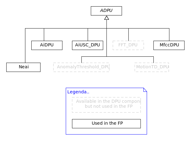
FP-AI-MONITOR1 uses the DPU displayed in the following image.
Note again that to optimize the performance of the multitasking system, the inference done by a DPU is performed in a concurrent task, and the function pack uses the following processing tasks:
- AI_USC_Task
- AITask
- MfccTask
- NeaiTask
Each processing task is the owner of the related DPU, and it uses all the features provided by the eLooM component.
5. Footnote and references
- ↑ "Thinking in C++, Volume 1, 2nd edition" (Bruce Eckel, president, MindView, Inc.)
- ↑ "The C++ Programming Language." (Bjarne Stroustrup)
- ↑ "Design patterns: Elements of reusable object-oriented software" (Erich Gamma, Richard Helm, Ralph Johnson, John Vlissides)
- ↑ . The PM state machine is a generic implementation of a state machine. It is named power-mode state machine only because, in the first products, the main purpose was to manage the low-power mode of the embedded application.
- ↑ eLooM supports single inheritance and multiple interfaces. This is different from the multiple inheritances supported by C++, but it is simple to implement in C and it adds flexibility to an embedded application.
- ↑ 6.0 6.1 6.2 6.3 Relative path of the Documentation folder of the function pack starting from the installation folder: FP_MONITOR1_V2.0.0\Documentation
6. Appendix A: UML® and color convention
The UML® diagrams presented in this article describe the architecture of some of the main elements of the function pack. Because of the dependency between the elements, a color convention is used to identify the package to which each element belongs, as displayed in the following image.
When the color is not specified (black for the foreground and text, and white for the background), then the element belongs to the main component described in the section.
