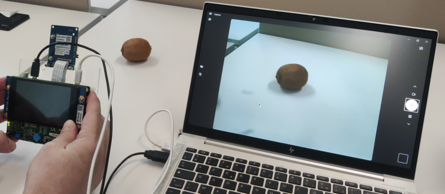
The STM32H747I-DISCO Discovery kit combined with the B-CAMS-OMV camera module can be used as a USB webcam. Using the STMicroelectronics kit for data collection helps achieve better results, as the same camera is used for data collection and inference once the model has been trained.
This article uses pictures and step-by-step instructions to demonstrate how to set up the board and camera module.
1. Setting up the board and camera module
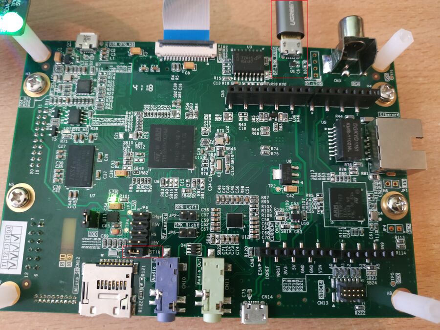
Plug the board into the computer using the ST-LINK port; this is typically done using a USB cable.
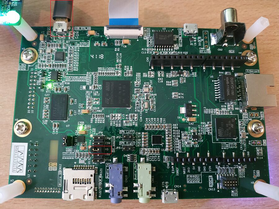
Locate the JP6 jumper on your board and ensure that it is set to the ST-LINK position. This setting allows the ST-LINK interface to communicate with the computer.
Once the USB connection has been established between the computer and the board, the board appears as a mounted device and its name is shown.
Download or clone the repository from the USB webcam application.
The binary file is located in x-cube-webcam/Binary/STM32H747I-DISCO_Webcam.bin.
Drag and drop the binary file into the mounted device to program it onto the board.
Unplug the board, change the JP6 jumper to the HS position, and plug the board using the USB OTG port.
2. Example using Windows® OS
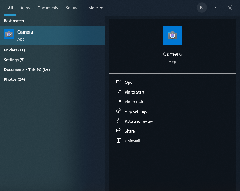
To open the Camera app using the Windows® operating system, press the Windows key, type camera, and press Enter.
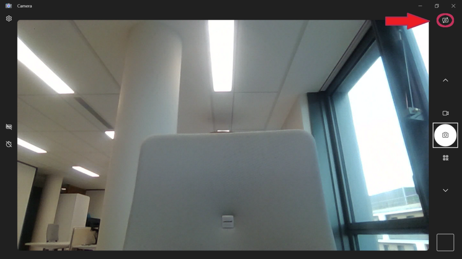
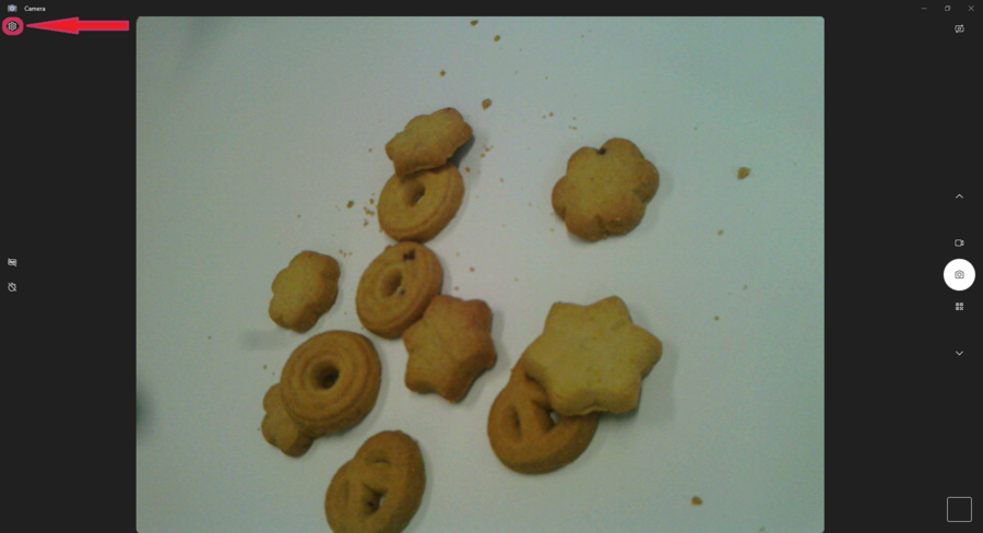
The default camera used by the Camera is the computer camera, and this is the image displayed on screen. The STM32 USB camera is also detected and can be selected by clicking on the icon in the top right corner, as shown below:
The screen now displays the image from the STM32 USB webcam. Click the gear icon in the top left corner to access the settings:
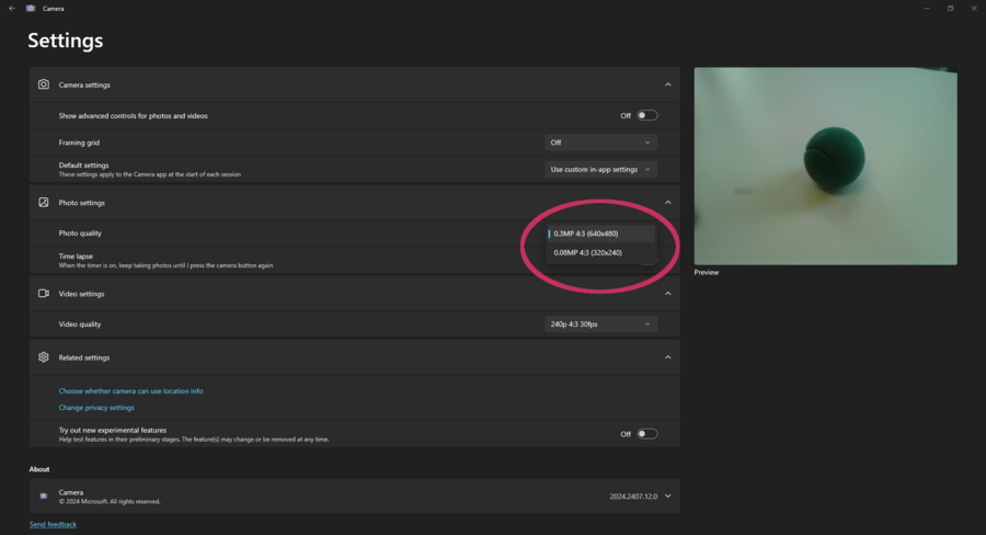
In the STM32 USB webcam settings, the photo capture image definition can be set to VGA or QVGA.
The application is now ready to capture the dataset with the board. If the dataset is used in an AI application, the performance can be increased by using the same camera pipeline.
